
A chemical hose system is an interface problem before it is a parts problem. Every joint in the chain — the hose end, the coupling, the clamp unit, the flange, the gasket and the mating pipe or tank nozzle — must agree on bore, standard, pressure class, temperature and electrical classification.
A hose that passes every bench test can still leak on site when one interface is mismatched. Most failures on transfer lines are interface failures rather than liner failures. This guide treats the chain as one chemical hose system, assigns each rating an owner, maps where mismatches occur, and closes with a pre-order checklist and a receiving routine.
About a 15-minute read at 250 words per minute; an interface map for ordering hose and fittings as one system.
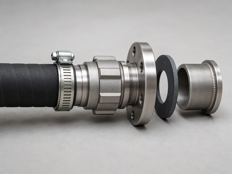
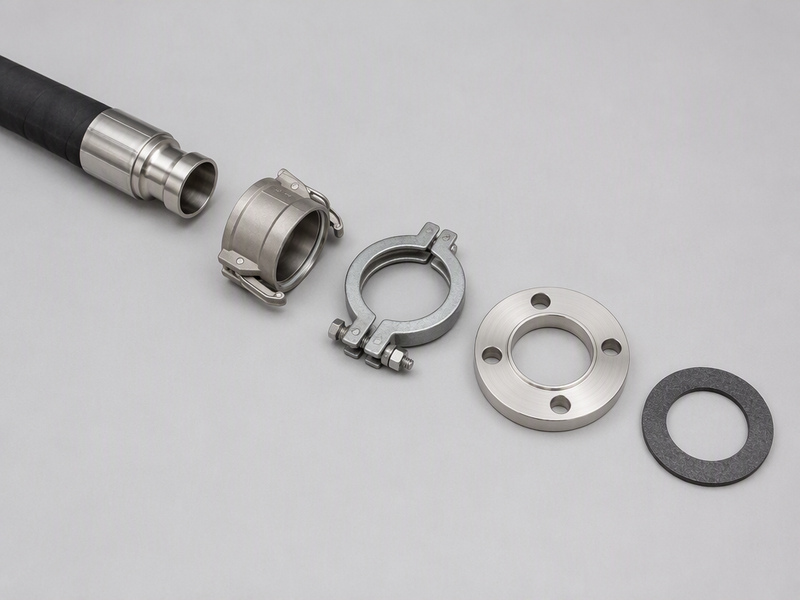
Figure 1. The six joints of one transfer line, shown in assembly order; each joint has to match the next.
Why a Chemical Hose System Is an Interface Problem
Two hoses can each meet EN 12115:2021 and still fail to connect to the same plant. A hose standard governs the tube, the reinforcement and the hose end at the factory. The thread cut into a tank nozzle, the bolt circle of a site flange and the gasket a maintenance fitter stocks belong to other standards and to other owners. Matching hose and fittings at the joint matters more than the rating of either part alone.
An interface failure follows a predictable pattern. The hose arrives, the coupling threads onto the nozzle, and the joint weeps, cracks or seizes after a few transfers. The root cause is rarely one faulty part. It is usually two correct parts that were never checked against each other.
Treat the whole path as one chemical hose system, and the question changes. Instead of asking which hose to buy, you ask which interfaces must agree. Bore is the first: the nominal diameter must run unbroken from hose to coupling to flange to pipe. Standard is the second: the same thread family or flange series has to sit on both sides of the joint.
Pressure class follows, because the weakest element sets the rating for the whole line. Temperature is the fourth, since the liner, the gasket and the coupling material each carry their own limit. Electrical classification closes the set, because a conductive path has to survive every interface, not only the hose.
That list is short, but each line hides a family of standards. The next section walks the chain joint by joint; the chemical hose complete guide covers the liner and media side.
The Joint Chain Inside a Chemical Hose System
Follow the fluid from the hose outward and the chain has a fixed order. Each link is defined by a standard, and each standard defines a set of mating dimensions. Interface compatibility means those dimensions line up on both sides of every link, and the chain then runs in a fixed sequence.
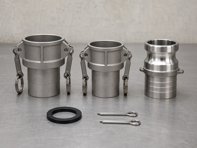
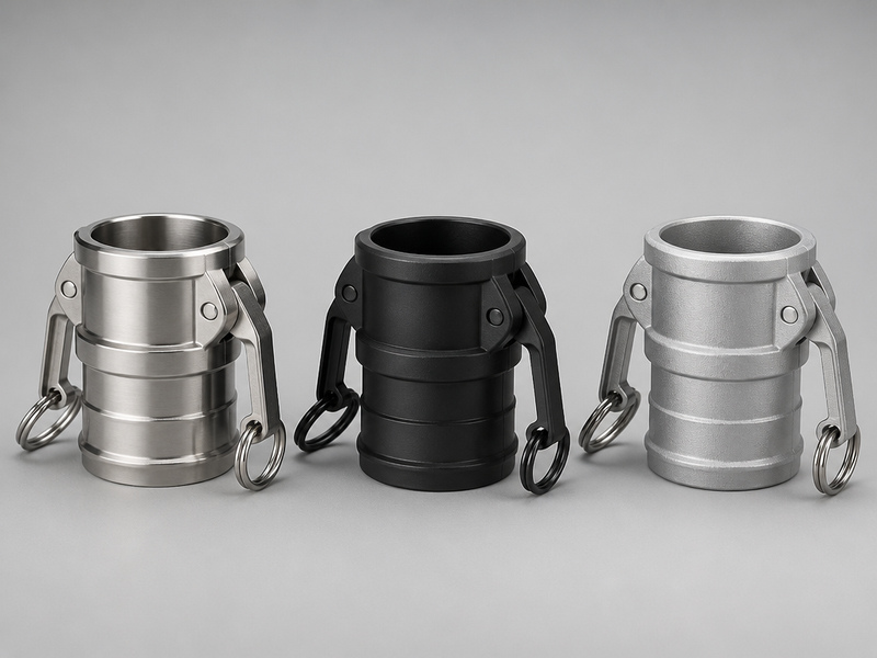
The hose end is the tail that enters the bore, defined in the EN 14420 series, Part 2, for hose side parts. The coupling joins that tail to the plant, with cam locking couplings under EN 14420-7 and the US cam and groove family under A-A-59326. Hose coupling compatibility starts with the coupling type letter and the material group, and the guide to hose couplings covers the full type range. EN 14420-7 applies to liquids, solids and gases, while liquefied gas and steam sit outside its range.
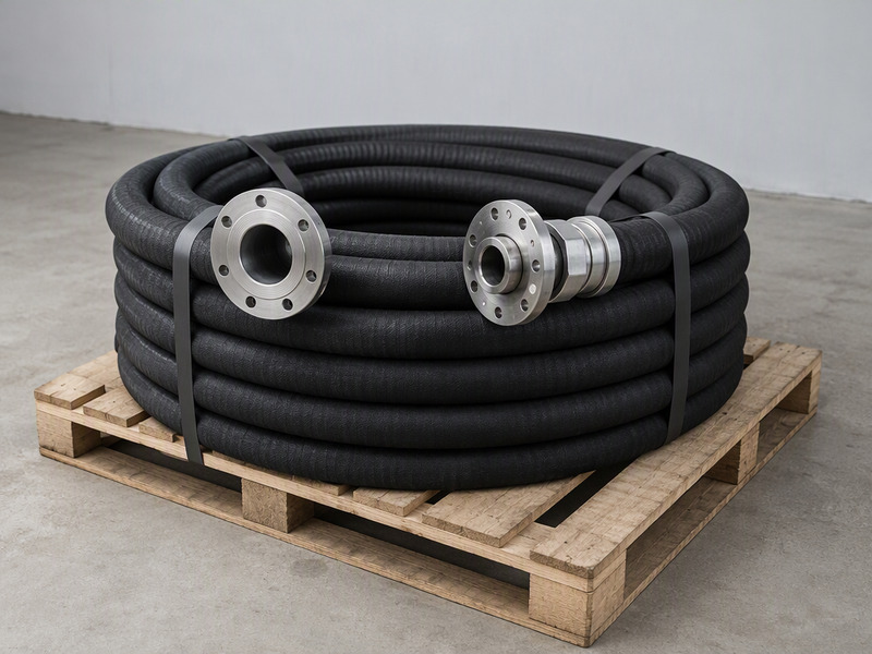
The clamp unit is the bolted or pinned band that grips the hose onto the tail, covered by EN 14420-3, Part 3. The flange is the bolted end covered by EN 14420-4 and dimensioned to EN 1092-1 or ASME B16.5. The gasket seals against both faces and is supplied as a PTFE envelope, EPDM or FKM insert. The mating pipe or tank nozzle is the site connection, owned by the plant and rarely covered by the hose standard.
Two links deserve emphasis. The clamp unit is the cheapest part and the easiest to under-size, so a clamp that matches the hose outside diameter can still be wrong for the pressure. The gasket disappears after assembly, so it is often replaced with whatever is on the shelf rather than the material the media needs.
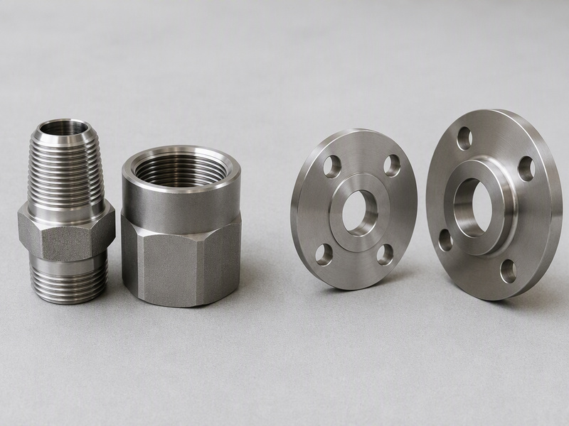
Figure 2. Thread families and flange pressure series are the two interface groups that cause the most cross-standard mismatches.
Because the same nominal bore can carry several mating dimensions, the standards have to be pinned down before anything is ordered.
Table 1. The six joints of a chemical hose system and the interface each one has to satisfy.
| Joint | Interface it defines | Reference | Typical mismatch |
|---|---|---|---|
| Hose end (tail) | Bore and tail profile into the hose | EN 14420-2 | Tail profile for the wrong hose construction |
| Coupling | Mechanical lock to the mating half | EN 14420-7, A-A-59326 | Cam type that will not lock with the site half |
| Clamp unit | Grip force on the hose and tail | EN 14420-3 | Clamp sized to the hose, not to the pressure |
| Flange | Bolt pattern and raised face | EN 1092-1 or ASME B16.5 | PN face bolted to a Class face |
| Gasket | Seal against both faces | Material choice, not a size | EPDM gasket in a solvent duty |
| Mating pipe or nozzle | Site thread or flange | Plant specification | NPT nozzle against a BSP tail |
A cam and groove family spans 1/2 in to 8 in, but a matching pair still needs the same type letter and a compatible material group. The type system behind those couplings is set out in the camlock fittings guide (planned URL — publish before linking).
Who Owns Each Rating in the Chain
Rating disputes usually start because nobody agreed who owns which number. On a chemical hose line, four parties hold pieces of one rating, and the finished assembly is only as strong as its weakest piece. Table 2 sets out the split.
The hose maker owns the pressure, temperature and electrical class of the hose itself; the coupling maker owns the mechanical rating of the fitting. The assembler owns the joint that ties the two together. The plant owns the nozzle and the real operating envelope. When a joint fails under review, those owners are usually pointing at one another.
The safest habit is to write the lowest rating on the purchase order and let every supplier read the same number. A 16 bar hose paired with a coupling rated lower is a 10 bar line, whatever the hose label says. Fix the rating chain on paper first, then price it.
Table 2. Who owns each rating on a chemical hose line and what the buyer confirms with each owner.
| Rating | Owner | What the owner sets | What to confirm |
|---|---|---|---|
| Working pressure | Hose maker and assembler | Rated pressure of the finished assembly | The lowest rating across hose, coupling and clamp |
| Temperature window | Liner and gasket suppliers | Continuous-service limits | Both the fluid and the ambient extremes |
| Thread or flange standard | Coupling maker and plant | Mating dimensions at the plant end | The actual nozzle, not a catalog default |
| Electrical classification | Hose maker | Resistance class of the hose | That continuity survives each metal joint |
| Assembly integrity | Assembler | Crimp or clamp quality | That test records travel with the assembly |
Hose coupling compatibility is not a single number. It is the sum of these owners agreeing on one rating chain before the order leaves the desk. Write it down, and the argument never starts.
Where Chemical Hose System Mismatches Actually Occur
Four interface groups account for most cross-standard problems. Each one looks like a size problem, and each one is really a standard problem. Hose coupling compatibility usually fails first at the thread family, then at the flange series. When a chemical hose system fails inspection, it is usually inside one of these four.
Thread families cause the most confusion, because NPT and BSP threads look alike and start to engage before they bind. The two families use different thread angles, so a pair can thread halfway and then leak or seize. The NPT vs BSP thread guide sets out the difference, and NPSM against NPT is a second version of the same trap.
Why do flange classes not interchange?
Flange pressure series cause the second of the four common mismatch groups. EN 1092-1 runs on a PN scale and ASME B16.5 on a Class scale, so two flanges can share a nominal bore and still differ in bolt circle and face depth. Bolting one to the other produces holes that almost line up.
Clamp sizing and gasket selection account for the last two groups. A clamp chosen by hose outside diameter alone can lose grip under pressure, and a gasket chosen by size rather than by fluid can swell or extrude. Both are covered in the clamp selection guide.
Table 3. The four interface groups where chemical hose system mismatches actually occur.
| Interface group | How the mismatch happens | Symptom on site | How to prevent it |
|---|---|---|---|
| Thread families | NPT against BSP, or NPSM against NPT | A fitting that threads halfway then leaks or seizes | Name the family and the size in writing |
| Flange pressure series | EN 1092-1 PN face against an ASME B16.5 Class face | Bolt holes that almost line up | Fix one flange system for the whole site |
| Clamp sizing | A clamp matched to hose outside diameter only | Weeping or hose pull-off under pressure | Size the clamp to the pressure and the tail |
| Gasket material | A seal chosen for size, not for the fluid | Swell, extrusion or a slow drip | Match PTFE envelope, EPDM or FKM to the media |
Note: a mismatch is not always visible at assembly. A threaded joint can pass a first pressure test and still work loose over a few thermal cycles, which is why the written family and size matter more than a hand fit.
Matching Bore, Pressure Class and Temperature
How do you check hose and fitting compatibility?
Bore, flange pressure class and temperature are the three values most often quoted separately and matched badly. Bore sets flow, pressure class sets the weakest element, and temperature narrows the material list. All three have to hold on both sides of every joint, because hose coupling compatibility depends on all three at once.
For plant transfer the working range runs from 3/4 in to 4 in, and cam and groove couplings cover 1/2 in to 8 in. Pressure classes cluster at 150 PSI (about 10 bar), 16 bar and 17 bar. Temperature is tighter than many buyers expect: EN 12115:2021 sets a service window of −20 °C to +65 °C, and EN 14420-7:2022 uses the same window for cam locking couplings.
One rule prevents most bore, pressure and temperature errors. Quote the value that survives the whole chain, not the value of the part in your hand.
Table 4. Common chemical hose bores, the pressure class usually supplied, and the mating end each bore must fit.
| Nominal bore | Hose pressure class | Camlock coverage | Interface note |
|---|---|---|---|
| 3/4 in | 150 PSI (about 10 bar) | Covered from 1/2 in | Small flanges often use a different system |
| 1 in | 150 PSI (about 10 bar) | Covered | Check the nozzle thread before ordering |
| 1-1/4 in | 16 bar | Covered | Match the flange series to the plant |
| 1-1/2 in | 16 bar | Covered | Common on tank-truck and rail unloading |
| 2 in | 16 bar | Covered | Often the last bore before camlock downsizing |
| 3 in | 17 bar | Covered to 8 in | Camlock pressure capability typically decreases with bore size |
| 4 in | 17 bar | Covered to 8 in | Confirm the clamp and flange rating together |
Burst pressure is a planning figure of roughly three to four times the working pressure. That margin absorbs surges and water hammer, and it is not an operating target. Size the line for the working class and let the margin stay unused.
Electrical Classification and Static Control at the Joint
EN 12115:2021 splits chemical hose into four electrical classes. A conductive class sits at or below 10⁶ Ω and a static-dissipative class at or below 10⁹ Ω, with both measured under EN ISO 8031. The class belongs to the hose, but the path to ground runs through the joints.
Every metal interface in the chain is a chance to break that path. A gasket that insulates the two flanges, a coated tail between the hose and the coupling, or a plastic coupling body can all interrupt continuity. Where flammable liquids move, OSHA requirements for bonding and grounding apply to the tank and the receiving vessel as well as to the hose.
The electrical classification is therefore a chain property. Specify the resistance class on the hose, then confirm that each joint keeps a metallic path from the hose end to the grounded plant connection.
Pre-Order Compatibility Checklist for a Chemical Hose System
A short checklist closes the gaps that a specification sheet leaves open. Walk it before the purchase order is written, and the late surprises disappear. Table 5 lists the checks against the six interfaces and the four owners. Every chemical hose assembly ordered this way carries a complete interface record, from hose and fittings to the plant nozzle.
Table 5. Pre-order compatibility checklist, mapped to the interface each check protects.
| Check | Interface it protects | What to record |
|---|---|---|
| Bore | Hose, coupling and flange bore | The nominal bore on the nozzle, the hose and the coupling end |
| Thread or flange | Mating dimensions | The exact family and series, repeated on the purchase order |
| Pressure class | Rating chain | The rating of every element and the lowest of the set |
| Temperature | Liner and gasket limits | The fluid and ambient extremes and the gasket limit |
| Electrical class | Conductive path | The resistance class and continuity across the joints |
| Media | Liner and gasket material | The fluid and its concentration against both materials |
| Assembly | Joint integrity | Whether the ends are factory-crimped or field-clamped |
| Documents | Traceability | The inspection documents that apply to the order |
One item deserves a note. EN 10204 defines the metal inspection document types, including the 3.1 certificate. It is a standard to request by name, not a claim about any single supplier, so list it only if the application calls for documented metal chemistry.
Receiving Inspection Routine
What should you check when a chemical hose arrives?
Receiving is the last chance to catch an interface mismatch before the hose goes into service. The check walks the same six interfaces, this time against the paperwork and the parts in the crate. Keep it short enough to finish on the dock.
The routine runs in a fixed order, set out in Table 6.
Table 6. Receiving inspection routine for a chemical hose assembly, in the order it is carried out.
| Step | Action | Interface checked |
|---|---|---|
| 1 | Match the packing list and delivery note against the purchase order | Order accuracy |
| 2 | Measure the bore at both ends and compare it with the ordered size | Bore |
| 3 | Check the coupling type letter and the thread or flange family | Thread or flange standard |
| 4 | Confirm the pressure class is marked and matches the specification | Pressure class |
| 5 | Inspect the clamp unit for correct size and full seating on the tail | Clamp unit |
| 6 | Verify the gasket material and any required spare seal | Gasket material |
| 7 | Check the electrical marking and the ground connection point | Electrical classification |
| 8 | Record the serial number, the date and any deviation in the log | Traceability |
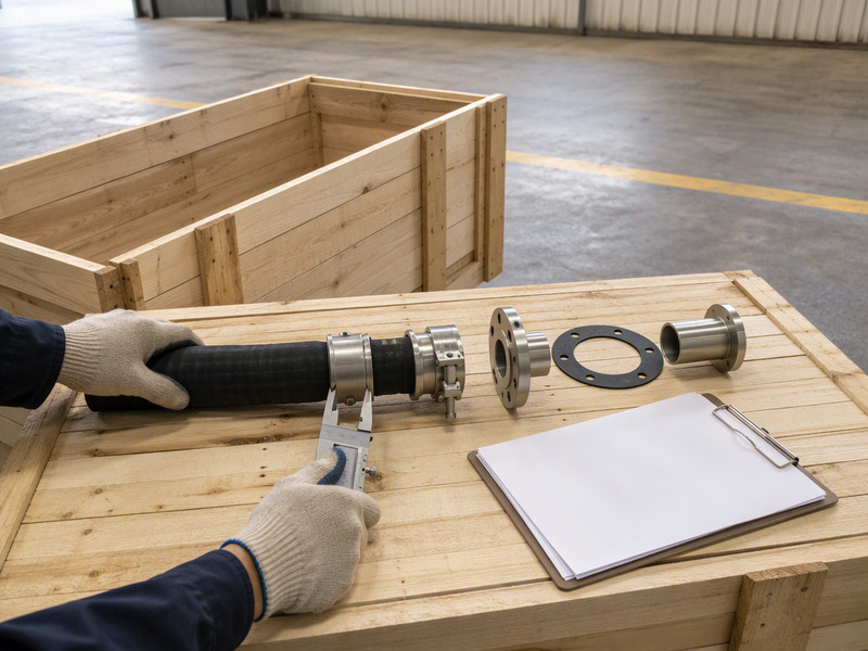
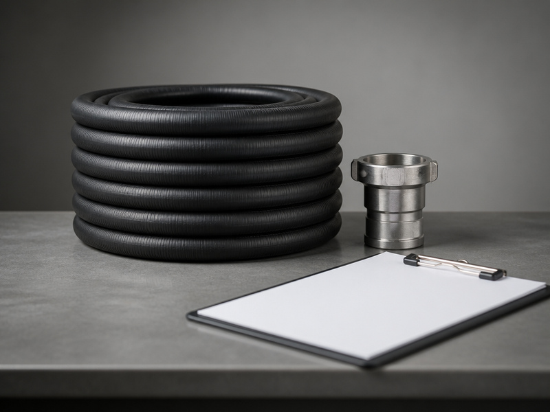
Figure 3. On the dock: the crate, the paperwork and the six interfaces checked before the hose reaches the line.
A deviation logged at receiving is cheap to fix. The same deviation found after the line is running is a shutdown risk.
Ordering the Whole Chain as One Package
Clamp unit or crimped end on a chemical hose line?
A clamp unit sets its own grip limit. A field-clamped end therefore carries the clamp rating rather than the hose rating. A factory-crimped end moves that joint into the works, where the pressure figure is declared once.
Ordering the whole chain as one package moves the interface risk to the supplier and keeps it off the plant floor. When hose and fittings come from one source, the bore, the standard, the pressure class, the temperature window and the electrical class are matched before the goods ship, and each chemical hose assembly arrives ready to install.
A single supplier for the whole chain keeps the rating chain on one document. HENGHUA supplies the hose and the fittings together, so one set of figures travels from the factory to the plant instead of being rebuilt at each handover. Where the plant later changes a nozzle or a gasket, only the interface that changed goes back for review against a known baseline.
For media-specific interface choices, the acid and alkali selection matrix (planned URL — publish before linking) narrows the liner and gasket combination by fluid. For flanged ends mixed with fixed and floating designs, the composite hose assembly guide (planned URL — publish before linking) explains the end options. Where the fitting material itself decides compatibility, the coupling material guide (planned URL — publish before linking) compares the boundaries of stainless, polypropylene and aluminum.
Chemical Hose System FAQs
What does a chemical hose system approach mean in practice?
It means matching the hose, coupling, clamp unit, flange, gasket and the mating nozzle as one chain rather than buying each part on its own. You confirm bore, standard, pressure class, temperature and electrical class at every joint before ordering. When one interface is left undefined, the line inherits the weakest rating and the highest risk.
Who owns the pressure rating of a finished assembly?
The hose maker owns the hose rating, the coupling maker owns the fitting rating and the assembler owns the joint, so the finished chemical hose assembly takes the rating of its weakest element. The safe habit is to record the lowest value on the purchase order and confirm each supplier reads the same figure. That single number prevents most rating disputes.
Why will an NPT fitting and a BSP fitting not seal together?
The two families differ in thread angle and pitch, so they can start to engage and then bind or leak before the joint seats. They look similar to the eye, which is exactly what makes them a common mismatch. Naming the family and its size in writing, and checking the nozzle before ordering, keeps the joint reliable.
Can I mix EN 1092-1 and ASME B16.5 flanges on one line?
Not directly. EN 1092-1 and ASME B16.5 are two separate flange systems, so a PN item and a Class item will not seat on each other at the same nominal bore. Their bolt circles and face depths follow different rules, which is why the holes can almost line up without sealing. Choose one system and repeat it at every nozzle.
How do I choose the right gasket material?
Match the gasket to the fluid and the temperature rather than to the flange size. A PTFE envelope suits aggressive media, EPDM suits many acids and bases, and FKM suits hydrocarbons and higher heat. Confirm the limit against the liner too, because a gasket that survives the fluid can still fail at the joint temperature.
What does electrical classification change at the joint?
EN 12115:2021 defines four electrical classes. The conductive class is capped at 10⁶ Ω and the static-dissipative class at 10⁹ Ω, both measured to EN ISO 8031. The class fits the hose, but continuity depends on the joints. An insulating gasket or a coated tail can break the path, so confirm a metallic route from the hose to the plant grounding point.
What should a receiving inspection check first?
Start with the paperwork, then the parts. Match the delivery note to the purchase order, measure the bore at each end, and confirm the coupling type, thread or flange family and pressure class against the order. Then inspect the clamp seating, the gasket material and the electrical marking. Log the serial number and any deviation before the assembly reaches the line.
How much pressure can a camlock coupling handle?
The pressure capability of a cam and groove coupling typically decreases with bore size and varies with the fitting material, so there is no single figure across the bore range. Metal couplings in the smaller bores usually carry the highest working pressure, and larger bores step down. Plastic bodies sit below the metal equivalents, so confirm the rating for the exact size and material.
Should the ends be factory-crimped or field-clamped?
Factory-crimped or factory-pressed ends give a repeatable joint with controlled equipment and test records, which suits higher pressure and flammable service. Field-clamped ends suit fast repairs and site flexibility, but they depend on the correct clamp unit and assembly care. Choose the method with the pressure class and the documentation requirement in mind.
About HENGHUA
HENGHUA is a professional hose and coupling manufacturer supplying global distributors, retailers and OEM brands. The chemical hose line covers UHMWPE (UPE), XLPE and PTFE liners and rubber constructions, including EPDM and oil-resistant synthetic rubber, with high-strength textile reinforcement and a steel helix for suction duty.
On the fitting side, the range covers camlock (cam and groove), flange, threaded and clamp-type terminations, and the factory can supply crimped assemblies, custom lengths, sheath printing, private label and OEM/ODM work. Commercial terms include factory-direct pricing, short lead times on bulk orders and a warranty.
 English
  Spanish
  Portuguese
  French
  German
  Arabic
  Russian
  Indonesian
  Japanese
  Korean