
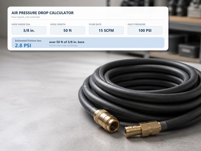
An air pressure drop calculator turns four inputs — flow rate, inside diameter, hose length, and inlet pressure — into the pressure your tool actually receives. When the result falls below 90 PSI at the tool, the hose is too narrow, the run is too long, or a coupler is strangling the line. This page gives you the inputs and where to find them. It also gives you a plain-English formula you can run by hand, a worked 3/8 inch example, two quick-reference tables, and the decision rules that turn a flow figure into a hose size you can order.
What the Calculator Solves For
The calculator answers one practical question. How much pressure survives the trip from the regulator to the tool? An air compressor is rated at the tank, but pneumatic tools work at the point of use. The line between the two quietly eats pressure, and the loss stays invisible at the tank gauge. A narrow air hose diameter can starve a sander that pulls 20 CFM while the gauge still reads a healthy 100 PSI.
Most workshops run an air compressor at 90–150 PSI and a tool rated at 90 PSI at the inlet. That leaves a working budget of roughly 5–15 PSI for friction, fittings, and couplers. The air pressure drop calculator tells you whether your hose fits inside that budget, and how far it misses when it does not. A pressure drop above that range shows up as a tool that stalls under load.
What an Air Pressure Drop Calculator Actually Computes
It computes friction loss: the pressure consumed by pushing compressed air through a tube. Air sliding along the inside wall of a hose loses energy to turbulence and wall friction. That energy loss shows up as a lower gauge reading at the far end. The effect is not linear. Loss climbs in a straight line with length, climbs with the square of flow, and falls steeply as the bore grows.
That last point surprises most buyers. Doubling flow quadruples the loss. Going from a 1/4 inch bore to a 3/8 inch bore cuts the same loss by roughly a factor of six. The reason is that friction scales with the inverse of inside diameter raised to a high power. Those two multipliers explain most undersized-hose complaints in a workshop. The physics behind compressed air flow is explored further in our note on compressed air friction loss in hoses.
A calculator does not measure leaks, a clogged filter, or a worn coupler that bleeds air. It covers the friction inside the hose, the fittings, and the couplers only. If the tank gauge is healthy but the tool feels weak, run the numbers first. Then hunt for mechanical faults before blaming the hose.
The Inputs You Need — and Where to Find Them
Five values drive the result. Four come from the job itself; the fifth comes from a short table of planning approximations.
- Flow rate — the air a tool consumes per minute, printed in the tool manual or catalog. Use the running figure, not the peak.
- Inside diameter — the measured bore of the hose, not the trade size stamped on the jacket. Fittings are often narrower.
- Hose length — the total run from regulator to tool, including every extension and leader hose.
- Inlet pressure — the pressure at the regulator where the hose starts, usually 90–100 PSI in a shop.
- Equivalent length of fittings — the extra straight-hose length each coupler, elbow, or reel adds.
Flow Rate and Duty Cycle
Flow is the value people get wrong most often. A tool catalog lists an average consumption figure, and that average is what the hose must feed continuously. An impact wrench rated at 4–5 CFM average can spike far higher for a fraction of a second. The hose still has to supply the average without starving the tool between cycles. Enter the running figure in SCFM, and add 20% when the tool runs continuously for long stretches.
Inside Diameter and Fitting Bore
Inside diameter decides how much air a hose can move at a given pressure. Trade size on the outside is a label, not a measurement. Two hoses sold as the same size can differ inside. Air hose sizes are quoted by inside diameter for exactly that reason. Measure the bore with a caliper or check the printed specification, and check the coupling bore too. A 3/8 inch hose necked down to a 1/4 inch coupler behaves like a 1/4 inch hose at that point. Our guide on how to measure air hose size walks through the measurement.
Hose Length, Reels, and Equivalent Length
Every foot of hose adds loss, and hardware adds hidden feet. Count one quick connect coupler pair at each end as 5–10 equivalent feet, then add it to the run before applying the formula. A 90° elbow counts as about 3 feet, and a hose reel as 10–15 feet. Air hose length should therefore be measured end to end, including the hardware, before you calculate anything.
The Formula in Plain English
The whole method rests on three multipliers. Length enters once, flow enters squared, and inside diameter enters to the fifth power in the denominator. For planning use, the relationship is usually written like this.
Loss (PSI) ≈ 0.0000018 × Length (ft) × Flow (SCFM)² ÷ Inside diameter (in.)⁵
This expression is the friction term only, with no fittings. Couplers, swivels and elbows add resistance beyond it, which is why the field planning band below is wider. Read the formula as a set of levers for compressed air flow rather than a precise prediction. Double the length and loss doubles. Double the flow and loss quadruples. Move up one nominal hose size and loss drops by roughly a factor of six.
The general form of this relationship, with a calibratable constant k, is set out in our compressed air friction loss guide; the coefficient above is calibrated for 100 PSI inlet, 70 °F and a straight run.
The formula assumes an inlet pressure of 90–100 PSI and a temperature near 70 °F (21 °C). It also assumes clean dry air, a smooth bore, and a straight run, so treat any quick connect coupler as extra equivalent length rather than part of the friction term. Change any of those and the real number moves. Any online calculator applies the same multipliers, with a few extra terms for fittings and altitude.
Worked Example: 50 ft of 3/8 Inch Hose at 12 SCFM
Run the air pressure drop calculator on a common shop setup. A 50 ft, 3/8 inch rubber hose feeds a spray gun that needs 12 CFM. The regulator is set to 100 PSI, and the air compressor holds that figure comfortably under load.
- Pick the flow — the spray gun average is 12 CFM.
- Confirm the bore — the hose measures 3/8 inch inside, and the fittings match the bore.
- Add equivalent length — 50 ft of hose plus one quick connect coupler pair at about 8 equivalent feet, the midpoint of the 5–10 equivalent feet planning range, gives 58 ft.
- Apply the formula — loss ≈ 0.0000018 × 58 × 12² ÷ 0.375⁵.
- Work the numbers — 12² = 144, so 0.0000018 × 58 × 144 = 0.015, and 0.375⁵ = 0.00742, giving about 2.0 PSI.
- Check the result — the tool sees roughly 98 PSI, comfortably above its 90 PSI rating.
Now run the same formula for compressed air flow in a 1/4 inch hose over the same 50 ft, at the site’s reference condition of 8 CFM. The smaller air hose diameter returns about 6.8 PSI of pressure drop at that flow: 0.0000018 × 58 × 64 ÷ 0.25⁵ ≈ 6.8 PSI. That is close to the 6 PSI field figure quoted elsewhere on this site. At 12 CFM the same bore gives about 13.5 PSI, because loss rises with the square of flow. Air hose length matters as much as the bore here, and why air hose size changes airflow explains the mechanism behind that drop.
Pressure Drop Quick-Reference Table: What Each Number Means
The table below is a planning estimate for clean, dry air at 100 PSI inlet and 70 °F, and it reports the friction term only. Air hose sizes are listed by inside diameter, and the values are rounded, so treat the table as a size-selection guide rather than a certification.
Table 1. Theoretical friction loss (friction term only, no fittings).
| Hose inside diameter | Flow rate (SCFM) | Loss per 25 ft (PSI) | Loss per 50 ft (PSI) | Loss per 100 ft (PSI) |
|---|---|---|---|---|
| 1/4 in. | 5 | 1.2 | 2.3 | 4.7 |
| 1/4 in. | 8 | 3.0 | 6.0 | 12 |
| 1/4 in. | 10 | 4.7 | 9.4 | 19 |
| 3/8 in. | 10 | 0.6 | 1.2 | 2.5 |
| 3/8 in. | 15 | 1.4 | 2.8 | 5.6 |
| 3/8 in. | 20 | 2.5 | 4.9 | 10 |
| 1/2 in. | 20 | 0.6 | 1.2 | 2.3 |
| 1/2 in. | 25 | 0.9 | 1.8 | 3.7 |
| 1/2 in. | 35 | 1.8 | 3.6 | 7.2 |
Read the table by finding the row that matches your bore and flow. The air hose sizes in the left column are inside diameters, so enter the measured air hose diameter rather than the trade size. These figures are the friction term only, so they sit below the site’s planning band. For field planning on 3/8 in. hose, use the site’s 2–5 PSI per 25 ft, i.e. 4–10 PSI over 50 ft once couplers, swivels and elbows are counted. Cross-check any row against the air hose size chart when your tool sits between two flow values.
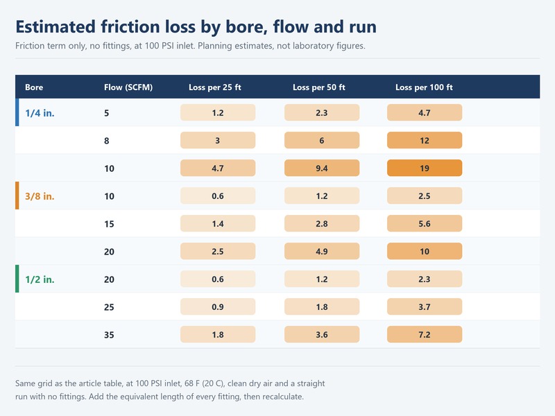
Figure 2. Estimated friction loss by bore, flow rate and run length at 100 PSI inlet.
How Do You Turn Pressure Drop Into a Hose Size?
Tables are useful, but decisions are faster. Once you know the tool type and the run length, the bore usually picks itself. Air hose sizes fall into three practical bands for shop work: 1/4 inch for light tools, 3/8 inch for most pneumatic tools, and 1/2 inch for long runs and high-demand equipment. Use the rules below, then confirm the numbers with the air pressure drop calculator.
Table 2. Air pressure drop calculator decision rules linking tool type to inside diameter and maximum run.
| Tool or application | Typical flow (SCFM) | Recommended inside diameter | Maximum run length |
|---|---|---|---|
| Air blow gun | 2–4 | 1/4 in. | 25 ft |
| Nailer or stapler | 3–6 | 1/4 in. | 25 ft |
| 1/2 in. impact wrench | 4–5 | 3/8 in. | 50 ft |
| Die grinder or drill | 5–10 | 3/8 in. | 50 ft |
| HVLP spray gun | 8–12 | 3/8 in. | 50 ft |
| Orbital sander | 15–20 | 3/8 in. | 50 ft |
| Sandblaster or high-demand tool | 20–35 | 1/2 in. | 100 ft |
These rules assume the same conditions as the table above. That means roughly 100 PSI at the regulator, one coupler pair, no reel, and a target of 90 PSI at the tool. When a run must exceed the listed maximum, step up one bore instead of accepting the loss. A 1/2 inch hose over 100 ft still delivers usable pressure where a 3/8 inch hose over the same distance would not. Between two sizes, the wider bore is almost always the cheaper mistake, especially when the air compressor is already working hard. Tool-specific guidance is in our page on what size air hose do I need.
A single bulk order on that bore can cover every station.

Figure 3. Decision rules that map tool type to inside diameter and maximum run length.
Input Mistakes That Skew Your Air Pressure Drop Calculator Result
Small data errors produce large sizing errors, because the formula squares flow and raises bore to the fifth power. Six mistakes account for most bad results.
- Using the trade size as the bore — a 3/8 inch hose is not always 0.375 inch inside. Measure the air hose diameter, or read the specification, before you calculate.
- Forgetting equivalent length — couplers, elbows, and reels can add 10–25% to the effective run. Ignore them and you understate the loss.
- Entering peak flow instead of average — peak figures overstate the loss, and average figures understate it. Use the running figure plus a margin for continuous duty.
- Assuming the regulator setting is the tool pressure — the gauge at the tank is not the gauge at the tool. Fit a second gauge at the tool to verify.
- Ignoring temperature and moisture — cold rubber stiffens, and hot, wet air changes density. The formula assumes 70 °F and dry air.
- Trusting a calculation over a leaking hose — friction loss and leakage loss are different problems, and no formula models a torn cover.
Air hose length is easy to fudge as well. A 50 ft coil routed around a workshop corner may travel 70 ft from regulator to tool, and every extra foot adds loss. Measure the real path, then add the equivalent length of the hardware. If the run cannot be shortened, the next bore up is the only reliable fix, and the calculation will show the improvement immediately.
When a Hose Must Be Replaced, Not Repaired
Replace the hose — never repair it — when it shows a bulge, a cut through the cover, exposed reinforcement, or a leaking crimp. Never exceed the manufacturer’s safe operating pressure. The rule is stated plainly in OSHA 29 CFR 1926.302(b)(5), and hoses over 1/2 inch must carry a safety device at the supply end under (b)(7). A leaking line is also a lost-pressure line, so a leak check supports the numbers instead of contradicting them.
Air Pressure Drop Calculator FAQs
What does an air pressure drop calculator actually measure?
It estimates friction loss: the pressure consumed as compressed air travels through a hose, fittings, and couplers. It does not measure leaks, a clogged filter, or a failing compressor. The output is the pressure the tool should see, given a flow rate, a bore, a length, and an inlet pressure. Compare that figure with the tool’s rated inlet pressure to judge whether the hose is suitable.
What is a normal pressure loss over 50 feet of hose?
The 3/8 inch bore at 12 CFM shows about 2–3 PSI of friction over 50 feet. That is the friction term only; for field planning on 3/8 in. hose, use the site’s 2–5 PSI per 25 ft, i.e. 4–10 PSI over 50 ft once couplers, swivels and elbows are counted. The 1/4 inch bore at the same flow loses far more and drops the tool below its rating. The air hose diameter you enter matters far more than most buyers expect.
Does the bore matter more than hose length?
Diameter usually dominates, because loss scales with the inverse of the bore raised to a high power. Length scales in a straight line, so halving the run halves the loss. Enlarging the bore by half can cut the loss by a factor of six. In practice, fix the bore first and shorten the run second. That sequence solves most weak-tool complaints. Air hose length then becomes a fine-tuning tool rather than the main fix.
Which flow figure should I enter for my air tool?
Enter the running consumption printed in the tool manual or catalog, not a peak or stall figure. A 1/2 inch impact wrench often averages 4–5 CFM, a die grinder 5–10 CFM, and a sander 15–20 CFM. Add about 20% when the tool runs continuously. If the manual lists a range, use the upper number so the hose is never the bottleneck.
Why is my tool weak when the gauge reads 90 PSI?
The gauge at the tank or regulator reads pressure before the hose, not at the tool. Friction and narrow fittings consume pressure along the run, so the tool may see far less than 90 PSI. Fit a gauge at the tool inlet and compare. If the reading is low, size up the bore, shorten the run, or replace restrictive couplers before touching the compressor.
How much pressure loss is acceptable?
A reasonable target is 5–15% of the inlet pressure, which is roughly 5–15 PSI when the regulator is set to 90–100 PSI. Staying under 10 PSI leaves useful headroom for cold days and partially blocked filters. If the loss exceeds 15%, resize the hose rather than raising the compressor output. More pressure at the tank simply increases the loss through the same restriction.
Does a quick connect coupler add pressure loss?
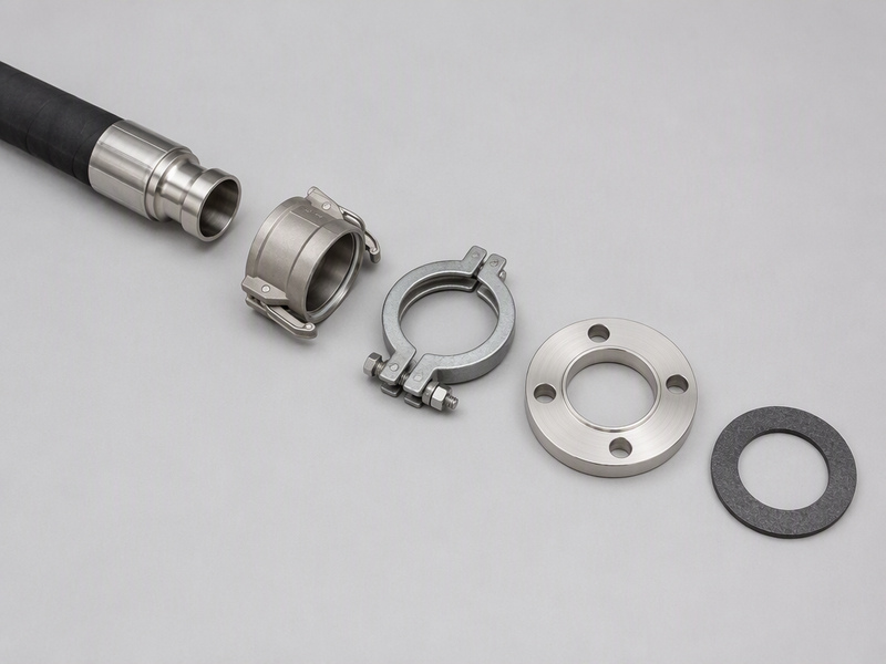
Yes, every coupler adds a little. Expect a quick connect coupler pair to add 5–10 equivalent feet to the effective run. That is enough to matter on a small bore or a long run, and worn or mismatched couplers can cost more. Keep couplers matched in bore, replace worn ones, and count their equivalent length before you size the hose.
Can a larger hose fix low pressure at the tool?
Often yes, provided the compressor can supply the volume. A wider bore lowers friction loss and delivers more pressure at the tool for the same flow. However, if the compressor cannot keep up, a larger hose will not create air that is not there. Source the supply first, then use the wider bore to stop wasting what the compressor produces. Standard air hose sizes stop at 1/2 inch in the ranges covered here.
Need the Hose the Numbers Point To?
A hose can only deliver what the compressor supplies. If the unit cannot hold 100 PSI under load, no bore change will fix a weak tool at the end of the line. Sizing the hose properly simply stops you wasting the compressed air flow you already pay for.
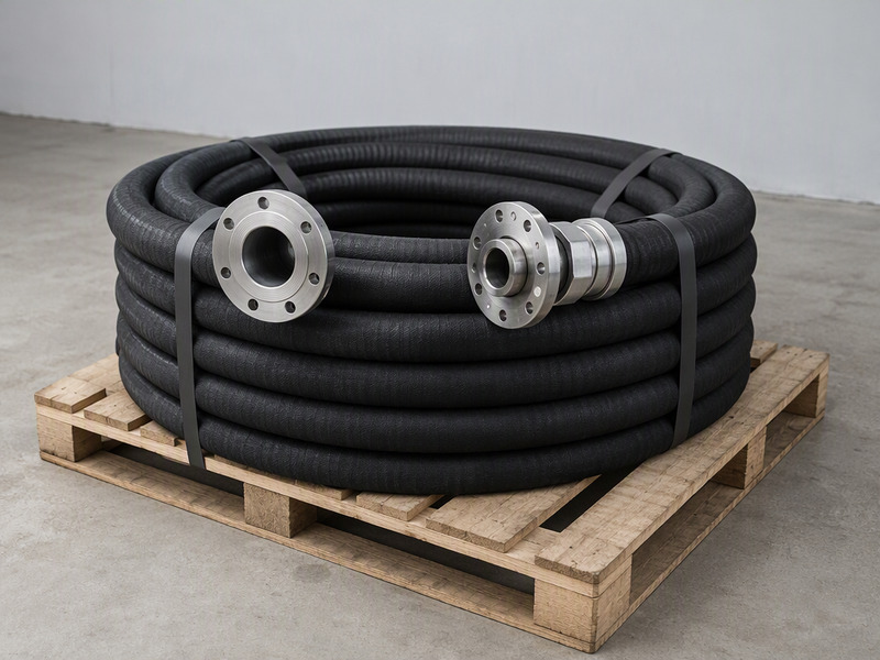
HENGHUA manufactures reinforced air hoses and complete hose assemblies for workshops, distributors, and OEM brands. Every air hose we build uses a high-tensile textile reinforcement layer with an abrasion- and oil-resistant cover, is rated 200–500 PSI, and leaves the factory with crimped brass fittings and a pressure test on every batch.
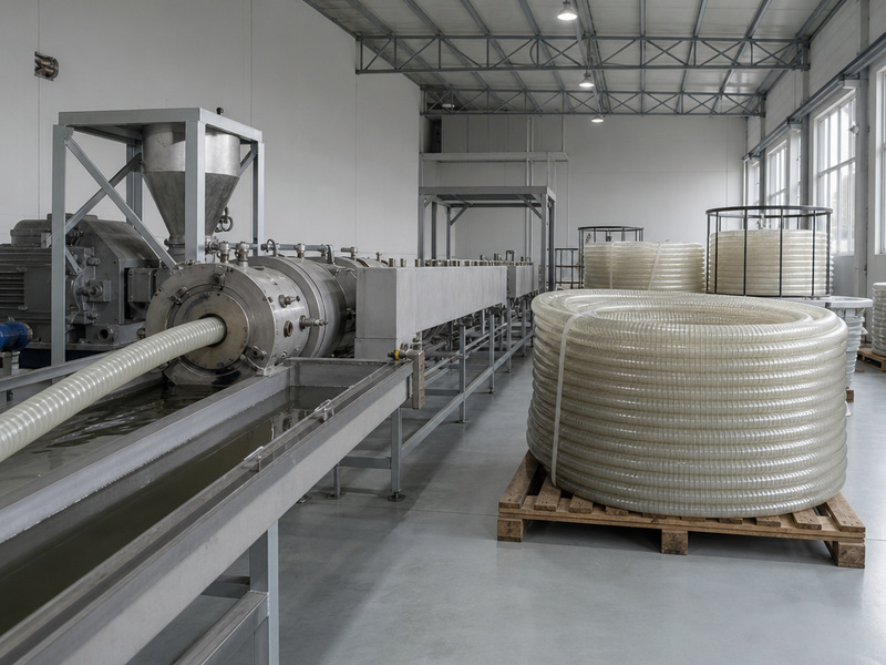
We supply 1/4, 3/8, and 1/2 inch bore in rubber, PVC, polyurethane, and hybrid constructions, with custom lengths, fittings, colours, reels, and OEM/ODM branding. Because we control compounding, extrusion, braiding, and crimping in one plant, lead times stay short for bulk orders and the specification on the label is the specification you get. If you are sourcing air hoses for retail, distribution, or industrial use, send us your specification and we will quote against it. Get a quote and free samples
Send us the flow figure from the tool label, the length of your longest run, and the number of couplers and fittings along it. We will return a hose specification that keeps the pressure at the tool above 90 PSI. Every bulk order leaves the plant with a batch pressure test report. For a single order we confirm coupler options and jacket material before production. Distributors planning a bulk order for a national retail program can ask about our air hoses range, private label options, and delivery schedules.
Final Verdict: Size From Numbers, Then Verify at the Tool
An air pressure drop calculator turns a vague sizing decision into a short calculation. Feed it the flow, the bore, the length, and the inlet pressure, and it returns the pressure your tool will really see. Fix the bore first, shorten the run where you can, count your fittings honestly, and keep the loss inside a 5–15 PSI budget. Then verify the result with a gauge at the tool, because the calculation models friction and hardware, not leaks or worn equipment.
Used consistently, the method replaces guesswork with a defensible specification. If it points to a 3/8 inch hose for most shop tools and a 1/2 inch hose for long runs, order that size. Stop paying for pressure you never deliver. Send your specification for a bulk order and we will quote the exact bore, length, and fittings your numbers call for.
Written by the HENGHUA engineering team, with input from workshop and maintenance teams across North America and Europe. HENGHUA manufactures reinforced air hoses and hose assemblies in rubber, PVC, polyurethane, and hybrid constructions, from 1/4 inch to 1/2 inch, rated 200–500 PSI, with custom lengths, fittings, colours, and OEM branding.
 English
  Spanish
  Portuguese
  French
  German
  Arabic
  Russian
  Indonesian
  Japanese
  Korean