
Why This 90 Degree Elbow One-Piece SAE Flange Fitting Passes the Compliance Gate
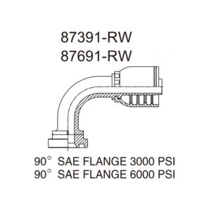
This 90 degree elbow one-piece SAE flange fitting is the 90 degree version of the HENGHUA 87391-RW family, built to the specification sheet title “90 DEGREE ELBOW SAE FLANGE 3000 PSI (ISO 12151-3, SAE J516)”. The flange head follows the SAE J518 / ISO 6162-1 Code 61 (3000 psi) dimension system, so it bolts straight onto Code 61 pads while the hose runs away at 90 degrees.
For OEMs the 90 degree outlet is the standard answer for ports that face structure, walls or adjacent components. For distributors the series covers the most requested elbow sizes in one table, including extended drop height options for deep installations. For maintenance teams the printed H column removes routing guesswork before the hose is cut, which reduces scrap on rebuild jobs.
- 90 degree elbow geometry with a Code 61 flange head
- Flange sizes 1/2″ to 2.1/2″ per the dimension chart
- Hose bores DN 12 to DN 50, dash -08 to -32
- Extended drop height options (H100), (H127) and (H150) for clearance-critical routes
- Series note: listed part numbers are for braided hoses; spiral hose versions use the 87392-XX-XXRW series
- 100% pressure tested, batch traceable, Made in China by the HENGHUA factory
Core Advantages
- 3000 psi Code 61 flange head. The flange end mates with SAE J518 / ISO 6162-1 Code 61 pads. A code 61 flange fitting is the default choice for most 3000 psi circuits in mobile and industrial hydraulics, and the SAE 3000 psi flange head pattern is shared across all sizes in this series.
- 90 degree routing in one part. A 90 degree SAE flange fitting turns the hose at the port, eliminating the extra elbow and adapter joint that a straight fitting would need.
- Extended drop height options. Part numbers with an (H100), (H127) or (H150) suffix fix the H dimension at 100, 127 or 150 mm, so the outlet clears deep flanges and tall valve decks.
- One-piece monobloc body. This one-piece SAE flange fitting has no loose flange head or collar, which cuts assembly time and removes a whole class of leak points.
- Braided and spiral twins. Keep the same flange geometry and switch to the 87392-XX-XXRW series when the hose construction is spiral.
Technical Specifications
What Is a 90 Degree Elbow One-Piece SAE Flange Fitting?
A flange type hydraulic hose fitting connects a hose end to a flanged port instead of a threaded one. This version turns the flow direction by 90 degrees between the flange head and the hose end, which is the standard angle when a hose must run parallel to the component face or when the port faces a wall. One-piece construction means the flange head, elbow and hose-end body are machined from a single blank.
When you compare code 61 vs code 62 flange fittings, remember that Code 61 is the 3000 psi series and Code 62 is the 6000 psi series. The 87391-RW is dimensioned for Code 61 (SAE J518 / ISO 6162-1) pads, and the hose-end interface follows ISO 12151-3, the standard behind the SAE J516 designation printed on the spec sheet.
Dimensional Data
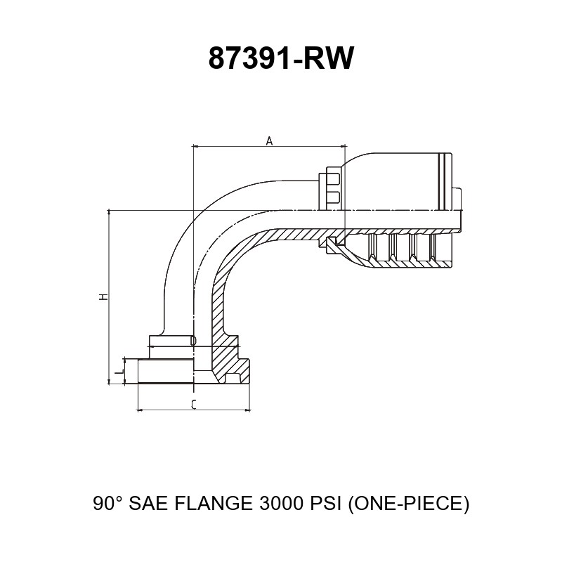
The dimension letters below are printed on the specification drawing and used as column headers in the matrix. All values are in millimetres. In the part number, an (Hxxx) suffix fixes the H dimension to the stated value, for example (H150) means H = 150 mm.
| Symbol | Description |
|---|---|
| A | Horizontal distance from the flange head centre line to the hose end of the elbow, as dimensioned on the drawing |
| C | Outside diameter of the flange head (Code 61 head) |
| D | Outside diameter of the neck section behind the flange head |
| H | Vertical distance from the bottom of the flange head to the hose-section centre line; (Hxxx) suffix sets a fixed value |
| L | Thickness of the flange head |
Full Dimension Table (Part Number Matrix)
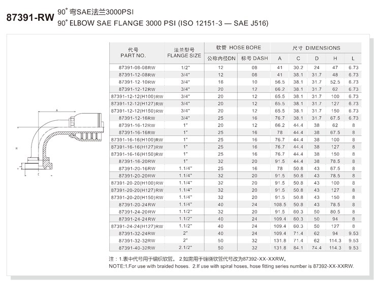
Read a part number as series – flange dash – hose dash, with an optional (Hxxx) drop height suffix. Flange dash and hose dash both count in 1/16 inch steps. Example: 87391-32-32RW means series 87391-RW, flange 2″ (-32), hose -32 (2″, DN 50). Example with fixed height: 87391-12-12(H150)RW means flange 3/4″, hose -12, with H fixed at 150 mm. The “RW” suffix marks this one-piece crimp series for braided hoses. Dimensions increase with flange size exactly as printed on the chart.
| PART NO. | FLANGE SIZE | HOSE BORE DN | HOSE BORE DASH | A | C | D | H | L |
|---|---|---|---|---|---|---|---|---|
| 87391-08-08RW | 1/2″ | 12 | 08 | 41 | 30.2 | 24 | 47 | 6.73 |
| 87391-12-08RW | 3/4″ | 12 | 08 | 41 | 38.1 | 31.7 | 48 | 6.73 |
| 87391-12-10RW | 3/4″ | 16 | 10 | 56.5 | 38.1 | 31.7 | 52.5 | 6.73 |
| 87391-12-12RW | 3/4″ | 20 | 12 | 66.2 | 38.1 | 31.7 | 62 | 6.73 |
| 87391-12-12(H100)RW | 3/4″ | 20 | 12 | 65.5 | 38.1 | 31.7 | 100 | 6.73 |
| 87391-12-12(H127)RW | 3/4″ | 20 | 12 | 65.5 | 38.1 | 31.7 | 127 | 6.73 |
| 87391-12-12(H150)RW | 3/4″ | 20 | 12 | 65.5 | 38.1 | 31.7 | 150 | 6.73 |
| 87391-12-16RW | 3/4″ | 25 | 16 | 76.7 | 38.1 | 31.7 | 67.5 | 6.73 |
| 87391-16-12RW | 1″ | 20 | 12 | 66.2 | 44.4 | 38 | 62 | 8 |
| 87391-16-16RW | 1″ | 25 | 16 | 78 | 44.4 | 38 | 67.5 | 8 |
| 87391-16-16(H100)RW | 1″ | 25 | 16 | 76.7 | 44.4 | 38 | 100 | 8 |
| 87391-16-16(H127)RW | 1″ | 25 | 16 | 76.7 | 44.4 | 38 | 127 | 8 |
| 87391-16-16(H150)RW | 1″ | 25 | 16 | 76.7 | 44.4 | 38 | 150 | 8 |
| 87391-16-20RW | 1″ | 32 | 20 | 91.5 | 44.4 | 38 | 78.5 | 8 |
| 87391-20-16RW | 1.1/4″ | 25 | 16 | 78 | 50.8 | 43 | 67.5 | 8 |
| 87391-20-20RW | 1.1/4″ | 32 | 20 | 91.5 | 50.8 | 43 | 78.5 | 8 |
| 87391-20-20(H100)RW | 1.1/4″ | 32 | 20 | 91.5 | 50.8 | 43 | 100 | 8 |
| 87391-20-20(H127)RW | 1.1/4″ | 32 | 20 | 91.5 | 50.8 | 43 | 127 | 8 |
| 87391-20-20(H150)RW | 1.1/4″ | 32 | 20 | 91.5 | 50.8 | 43 | 150 | 8 |
| 87391-20-24RW | 1.1/4″ | 40 | 24 | 108.5 | 50.8 | 43 | 78.5 | 8 |
| 87391-24-20RW | 1.1/2″ | 32 | 20 | 91.5 | 60.3 | 50 | 80.5 | 8 |
| 87391-24-24RW | 1.1/2″ | 40 | 24 | 109.4 | 60.3 | 50 | 94 | 8 |
| 87391-24-24(H127)RW | 1.1/2″ | 40 | 24 | 109.4 | 60.3 | 50 | 127 | 8 |
| 87391-32-24RW | 2″ | 40 | 24 | 109.4 | 71.4 | 62 | 94 | 9.53 |
| 87391-32-32RW | 2″ | 50 | 32 | 131.8 | 71.4 | 62 | 114.3 | 9.53 |
| 87391-40-32RW | 2.1/2″ | 50 | 32 | 131.8 | 84.1 | 74.4 | 114.3 | 9.53 |
Hose Series: Braided and Spiral Versions
The chart note on the specification sheet is the buying rule. Note 1: for use with braided hoses. Note 2: if use with spiral hoses, the hose fitting series number is 87392-XX-XXRW. The flange head geometry stays on the same Code 61 pad, but the hose-end body is different because spiral hose constructions need a different crimp profile.
| Hose construction | Use series | Part number example |
|---|---|---|
| Braided hose | 87391-RW | 87391-32-32RW |
| Spiral hose | 87392-RW | 87392-32-32RW |
When you order, tell us the hose brand, hose bore and working pressure so we can confirm the correct series and crimp data sheet.
Material and Heat Treatment
| Item | Standard offer | Options |
|---|---|---|
| Body material | High-strength cold-headed or forged carbon steel (20#, 35#, 45#) | 304 or 316L stainless steel |
| Heat treatment | Carburizing and quenching, core hardness HRC 20-28, batch hardness records kept | Per drawing |
| Surface finish | Trivalent zinc plating (96 h salt spray) | Zinc-nickel (720 h), Dacromet (1000 h) |
| Testing | 100% pressure test, thread and gauge inspection where applicable | MTR, BV/SGS third-party inspection |
Working Pressure and Operating Envelope
| Parameter | Value |
|---|---|
| Flange system | SAE J518 / ISO 6162-1 Code 61, 3000 psi series |
| Series pressure class | 3000 psi nominal, size-graded per the standard |
| Hose-end standard | ISO 12151-3 (SAE J516), as printed on the spec sheet |
| Assembly rating | Limited by the hose rating; always verify with the HENGHUA crimp data sheet provided with every order |
| Temperature range | Typical -40 degrees C to +120 degrees C; system derating depends on hose and seal materials |
| Factory test | 100% pressure test before dispatch |
The 3000 psi class does not mean every size runs at 3000 psi. The pressure capability of a finished assembly is the lowest rating among hose, fitting and flange size, so confirm the size-dependent rating on the standard table or our data sheet before design release. SAE 3000 psi flange fittings are graded per flange size, so always match the part number to the pad rating. If the application is an excavator, loader or industrial power unit, tell us the machine and circuit, and we will confirm which code 61 flange fitting size applies.
Selection and Ordering
How to Read the Part Number Matrix
- Segment 1 is the series: 87391-RW for 90 degree elbow one-piece flange fittings on braided hose.
- Segment 2 is the flange dash, equal to the Code 61 flange size in 1/16 inch increments: 08 = 1/2″, 12 = 3/4″, 16 = 1″, 20 = 1.1/4″, 24 = 1.1/2″, 32 = 2″, 40 = 2.1/2″.
- Segment 3 is the hose dash in 1/16 inch increments: 08 = DN 12, 10 = DN 16, 12 = DN 20, 16 = DN 25, 20 = DN 32, 24 = DN 40, 32 = DN 50.
- An optional (Hxxx) suffix sets the drop height H to 100, 127 or 150 mm for clearance-critical routes.
- The RW suffix identifies the one-piece crimp series; it does not change the flange dimension logic.
Check your selection against the table above before ordering. A wrong flange dash will not bolt to the Code 61 pad, and a wrong hose dash will not crimp cleanly.
Flange Size and Dash Size Chart
| FLANGE SIZE | Flange dash | Available hose dashes in series |
|---|---|---|
| 1/2″ | 08 | 08 |
| 3/4″ | 12 | 08, 10, 12, 16 |
| 1″ | 16 | 12, 16, 20 |
| 1.1/4″ | 20 | 16, 20, 24 |
| 1.1/2″ | 24 | 20, 24 |
| 2″ | 32 | 24, 32 |
| 2.1/2″ | 40 | 32 |
Cross Reference Service
Do you have a legacy or OEM part number from an old machine and no drawing? Send us the number, a photo and the basic dimensions. We match flange size, hose dash and the A and H elbow dimensions, including (Hxxx) drop height variants, against the 87391-RW matrix and reply with a cross reference proposal within 24 hours. The service is free, and samples can be shipped worldwide for verification.
Packaging and Logistics
| Item | Detail |
|---|---|
| Inner pack | 10 pcs per box, labeled with part number and batch |
| Carton | Batch-packed with packing list, gross/net weight marked |
| Batch mark | Batch number on every box for full traceability |
| Origin | Made in China, HENGHUA factory |
| Documents | MTR and inspection report on request; COC available |
| Lead time | Standard sizes from stock or short production cycles; confirm at quotation |
Assembly and Use Guide
Four-Step Crimping Procedure
- Cut the hose square with a sharp blade; a vertical cut protects the wire layer.
- Mark the insertion depth shown on the HENGHUA crimp data sheet supplied with every order.
- Apply assembly lubricant and push the hose onto the fitting up to the depth mark.
- Crimp in one continuous stroke, then verify the crimp outside diameter with a caliper against the data sheet value.
Never guess the crimp outside diameter. Every order ships with its crimp data sheet, and the value is specific to hose brand and construction.
Mounting the Flange Connection
- Face the flange head squarely onto the Code 61 pad and check the O-ring groove is clean.
- Fit the O-ring for the flange size; the O-ring is the seal, so replace it whenever the joint is opened.
- Confirm the 90 degree outlet direction is aimed at the hose route before you tighten.
- Bring the flange together evenly and tighten the bolts in a diagonal sequence.
- Apply the torque value from the flange data sheet; do not rely on feel.
Installation Warnings
- Do not mix hose, fitting or ferrule components from different sources; parts are released as a matched set.
- Do not use a braided-hose fitting on a spiral hose, and never swap 87391-RW parts into a spiral assembly; order the 87392-XX-XXRW series instead.
- Flange bolts and O-rings are not part of the fitting; order them to the flange size separately.
- Crimping is a one-way operation. A one-piece SAE flange fitting cannot be re-crimped after a failed first attempt, so verify the setup before pulling the trigger.
- Do not reuse a fitting pulled from an old hose assembly; the crimp zone has already yielded.
- When you need extra clearance, order the (Hxxx) drop height variant instead of bending the hose or adding a spacer under the flange.
OEM Customization and Quality Traceability
Customization Options
- Custom hose-end and dash combinations within the Code 61 flange range
- Custom drop height H values beyond the printed (H100), (H127) and (H150) options
- Surface finish choice: trivalent zinc, zinc-nickel or Dacromet for the environment
- Laser marking of customer logo, part number and batch code
- Stainless steel material option in 304 or 316L
- Custom packaging and export documentation per OEM requirement
Quality and Traceability System
Every fitting moves through incoming material check, cold heading or forging, machining, heat treatment, surface finishing, 100% dimensional inspection, 100% pressure test, marking and packaging. The batch number on the box links back to the material heat number, heat treatment records and inspection reports, so any field question can be answered with documents instead of opinions. Third-party inspection by BV or SGS can be arranged before shipment.
FAQ
1. What standard is the 87391-RW 90 degree elbow one-piece SAE flange fitting made to? The hose-end dimensions follow ISO 12151-3 / SAE J516 as printed on the spec sheet title, and the flange head follows the SAE J518 / ISO 6162-1 Code 61 system, which is the 3000 psi series.
2. What does the (Hxxx) suffix in the part number mean? It fixes the drop height H to a set value. For example, 87391-12-12(H150)RW has H = 150 mm. The chart lists (H100), (H127) and (H150) options for the most popular sizes, and a 24-24 (H127) option on the 1.1/2″ flange.
3. Why choose a 90 degree SAE flange fitting instead of a straight or 45 degree version? The 90 degree outlet runs the hose parallel to the component face, which is the standard solution when the port faces a wall, a guard or another component. The printed H column lets you verify the outlet height before cutting any hose. A 90 degree SAE flange fitting is the routing answer when the hose must turn immediately at the port.
4. What pressure rating does this SAE flange hydraulic hose fitting carry? This 90 degree SAE flange fitting carries the 3000 psi Code 61 class rating. The finished assembly pressure depends on the hose rating and the flange size, so confirm the size-dependent rating and the crimp data sheet before production.
5. Can I use this one-piece SAE flange fitting with spiral hose? No. The chart note says the listed part numbers are for braided hoses. For spiral hose, order the 87392-XX-XXRW series, which keeps the same Code 61 flange head and 90 degree geometry.
6. Which flange and hose sizes are available? Flange sizes run from 1/2″ to 2.1/2″ and hose bores from DN 12 to DN 50 (dash -08 to -32). The full dimension table lists twenty-six standard and extended drop height combinations. The table covers the full SAE 3000 psi flange size range available in this series. Every code 61 flange fitting size in the table follows the same part number logic.
7. How do I identify the size I need? Read the part number as series – flange dash – hose dash. For example, 87391-32-24RW means flange 2″ and hose -24. Add the (Hxxx) suffix only when the routing needs a fixed drop height.
8. Are flange bolts and O-rings included? They are not part of the fitting. Order bolts and O-rings to the Code 61 flange size separately, and use the torque value from the flange data sheet.
Request a Quote
Send us the hose type, flange size and dash size, or simply your legacy part number. Tell us the quantity, surface finish, required drop height and whether stainless steel is required, and our engineers will confirm the correct 87391-RW part number with drawings and the crimp data sheet. OEM inquiries for custom 90 degree one-piece SAE flange fittings and private label marking are welcome. Expect a reply within 24 hours and sample support before you commit to a series order.
Browse the full Flange Fittings range for the complete family, or contact us to request a quote, mill test reports, and samples.

 English
  Spanish
  Portuguese
  French
  German