
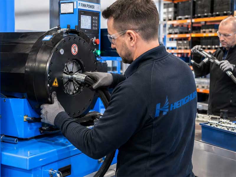
Hydraulic hose assembly crimping is a cold-forming process that uses radial compression to permanently attach a metal ferrule to a hose end, creating a pressure-rated, leak-proof connection for hydraulic fluid transmission. The process requires precise control of crimp diameter, die selection, and insertion depth—each specific to the hose and fitting combination. A correctly crimped assembly is designed to withstand impulse cycles, vibration, and temperature extremes over its service life. One of the most important principles: never use a crimp setting that has not been validated for that exact hose, fitting, and crimper combination.
Hydraulic Hose Assembly Crimping at a Glance
| Item | Description |
|---|---|
| Definition | Permanent attachment of fittings to hydraulic hoses using radial compression |
| Main equipment | Hydraulic hose crimping machine with interchangeable die sets |
| Critical parameter | Finished crimp diameter (must be within validated tolerance) |
| Required document | Manufacturer-approved crimp chart for the specific hose and fitting combination |
| Quality verification | Dimensional inspection, visual check, proof test, and impulse test (per application) |
| Most common failure cause | Incorrect hose/fitting combination or wrong crimp setting |
| Primary standards | SAE J343, SAE J517, ISO 18752, ISO 6802, ISO 6803 |
Key Takeaways
- Use only hose and fitting combinations validated together by the manufacturer or through your own qualification testing.
- Obtain the target finished crimp diameter exclusively from the approved crimp chart—never calculate it from hose OD and ferrule thickness.
- Confirm full fitting insertion depth before crimping; mark a witness line on the hose at the ferrule edge.
- Measure the finished crimp diameter at the specified positions with calibrated instruments; record every measurement.
- Test and document assemblies according to the applicable hose standard, customer specification, or validated internal procedure.
- Replace crimper dies when they show wear or dimensional change—establish a replacement interval based on your production volume and inspection results.
What Is a Hydraulic Hose Assembly?
A hydraulic hose assembly is a flexible conduit consisting of a reinforced rubber or thermoplastic hose with permanently attached end fittings. It transmits pressurized hydraulic fluid within a closed-loop system, converting fluid power into mechanical motion or force.
Three primary components:
- Inner tube – The fluid-carrying layer, typically made of nitrile (NBR), hydrogenated nitrile (HNBR), or PTFE, selected for compatibility with the hydraulic fluid and operating temperature range.
- Reinforcement – One or more layers of textile braid, steel wire braid, or steel wire spiral that provides pressure-containing strength. The reinforcement construction determines the hose’s pressure rating, flexibility, and impulse performance.
- Outer cover – A rubber or thermoplastic layer that protects the reinforcement from abrasion, ozone, UV exposure, and chemical attack.
The completed assembly functions as a critical safety component: a failure can result in fluid injection injuries, environmental contamination, equipment damage, and costly unplanned downtime.
How Does Hydraulic Hose Crimping Work?
Crimping is a cold-forming process. The assembly operator inserts the prepared hose end into the fitting nipple until it bottoms against an internal shoulder. The fitting ferrule (outer collar) is then placed over the hose outer cover. A crimping machine uses segmented dies that close radially inward around the ferrule, compressing it plastically against the hose layers.
The key physical principle is interference fit: the crimped ferrule must compress the hose reinforcement to a controlled final diameter—small enough to create mechanical grip on the fitting nipple, yet large enough to avoid cutting or overstressing the reinforcement wires.
Crimp force is applied hydraulically or mechanically. The required force depends on:
- Ferrule material and wall thickness
- Hose reinforcement type and outer diameter tolerance
- Required reduction in diameter (interference)
The machine does not “know” when to stop; the operator controls the closure to a target finished diameter based on a validated crimp chart. After the dies retract, the ferrule may exhibit a small amount of spring-back (elastic recovery). The crimp chart accounts for this by specifying a measured diameter taken a set time after crimping.
Important safety note: Crimping machines generate high forces. Only trained personnel should operate them. Never place hands inside the die area during closure. Follow the machine manufacturer’s lockout/tagout procedures during die changes and maintenance.
Hydraulic Hose Crimp Chart Explained
A crimp chart (also called a crimp specification or set-up chart) is the single most important document in a hydraulic hose assembly workshop. It provides the validated target dimensions for a specific combination of hose manufacturer and series, fitting manufacturer and series, ferrule type, and crimping machine model.
Typical Crimp Chart Entry
| Field | Example Value |
|---|---|
| Hose series | SAE 100R2AT |
| Hose dash size | -08 (DN12) |
| Fitting series | ABC-08-xx |
| Ferrule part number | ABC-F08 |
| Die set to use | XYZ Die Set No. 8 |
| Target finished crimp diameter (after spring-back) | 26.20 mm ± 0.13 mm |
| Crimp length (die land engagement) | 32.0 mm |
| Skive length (if applicable) | Not required |
| Insertion depth mark | 2.0 mm from ferrule edge |
How to Use the Chart
- Identify the exact hose and fitting series you are assembling.
- Locate the row for that specific combination.
- Note the target finished crimp diameter and tolerance.
- Install the specified die set into the crimping machine.
- Perform a test crimp on a sample assembly.
- Measure the finished diameter with a calibrated instrument.
- Adjust the machine setting until the measured diameter falls within the specified tolerance.
- Record the final machine setting and measured diameter for the production run.
Critical rule: Do not use a crimp chart from a different hose or fitting brand, even if the series designation appears identical. Do not calculate a production crimp diameter from hose OD and ferrule thickness alone.
Hydraulic Hose Crimping Process Step by Step
The following sequence assumes a no-skive, permanent crimp fitting on a wire-braid hydraulic hose. Always follow the specific procedure for your hose and fitting combination.
Step 1: Verify Material Compatibility
- Confirm the hose series matches the fitting series.
- Check that the hose batch has not exceeded its recommended storage life per the manufacturer’s guidelines.
- Ensure the work area is clean and free of contamination sources.
Step 2: Cut the Hose Squarely
- Use a guided saw or abrasive cutter with a clean, sharp blade.
- The cut must be perpendicular to the hose axis: 90° ± 0.5°.
- Remove any rubber dust or debris from the cut end using clean, dry compressed air or a lint-free cloth.
Step 3: Mark Insertion Depth
- Use the fitting manufacturer’s specification to determine the correct insertion depth.
- Measure from the end of the hose and mark a witness line on the outer cover. This line indicates where the ferrule edge should sit after insertion.
- For skive-type fittings, mark the skive length and remove the outer cover using a skiving machine; avoid nicking the reinforcement wires.
Step 4: Lubricate the Fitting Nipple and Hose Interior
- Apply a thin, even layer of the lubricant specified by the fitting manufacturer (typically a light mineral oil or assembly lubricant).
- Lubrication reduces insertion friction and prevents the inner tube from tearing or rolling during assembly.
- Do not over-lubricate; excess oil can cause the fitting to slip during crimping or attract contamination.
Step 5: Insert the Fitting into the Hose
- Push the fitting nipple into the hose end until the internal shoulder contacts the hose end.
- The witness line you marked in Step 3 should align with the edge of the ferrule.
- For hoses with larger diameters or tight tolerances, a fitting insertion tool or hydraulic press may be required. Never hammer the fitting into the hose.
Step 6: Select and Install the Correct Die Set
- Refer to the crimp chart for the specified die set.
- Inspect the dies before installation: check for wear, scoring, or damage.
- Install the die set into the crimping machine per the manufacturer’s instructions.
Step 7: Position the Assembly in the Crimper
- Place the ferrule squarely within the die opening.
- Ensure the full ferrule length is within the die land area; do not crimp partially off-center.
- Actuate the crimping cycle in a single, smooth closure. Do not make multiple partial crimps.
Step 8: Complete the Crimp Cycle
- Hold the full crimp pressure for the duration specified in the machine manufacturer’s guidelines.
- The dies will retract automatically or manually, depending on the machine type.
- Allow the assembly to remain undisturbed for a few seconds to allow for any elastic recovery.
Step 9: Measure the Finished Crimp Diameter
- Use a calibrated digital caliper or a dedicated crimp-diameter gauge.
- Measure at the center of the ferrule length.
- Take two measurements 90° apart around the circumference.
- Calculate the average and record the value.
Step 10: Inspect and Document
- Visually inspect the ferrule and hose for any abnormalities: cracks, scoring, wrinkling, or exposed reinforcement.
- Check that the hose cover has been uniformly compressed.
- Record the measured crimp diameter, operator ID, batch number, and date in a production log.
- If the assembly is for a critical application, attach a traceability label for future reference.
Hydraulic Hose Fitting Selection Guide
Fitting selection begins with the hose specification and the equipment port requirements. These seven criteria must be matched:
- Hose series and dash size – e.g., SAE 100R2AT-08 (DN12). The fitting must be manufactured for that specific hose series.
- Working pressure – The assembly’s maximum working pressure is determined by the lowest-rated component in the system.
- Fitting connection end – Must match the equipment port.
- Fitting material – Carbon steel with zinc plating is standard; stainless steel 316 for corrosive environments.
- Orientation – Straight, 45°, 90°, or multi-angle block fittings.
- Skive or no-skive – Some fittings require removing the outer cover to a precise length.
- Reusability – Permanent crimp fittings for high-pressure applications; reusable for field repairs and low-pressure systems.
Fitting Connection Type Comparison
| Connection Type | Sealing Mechanism | Typical Applications | Illustrative Pressure Capability* |
|---|---|---|---|
| JIC 37° Flare | Metal-to-metal 37° seat | Mobile equipment, industrial hydraulics | Manufacturer and size dependent |
| ORFS (O-Ring Face Seal) | O-ring compressed against flat face | High-vibration, zero-leak systems | Manufacturer and size dependent |
| SAE 4-Bolt Flange | O-ring + clamp load | High-flow, high-pressure systems | Manufacturer and size dependent |
| BSPP (G-thread) | Bonded washer or O-ring | European-origin equipment | Manufacturer and size dependent |
| NPTF (Dryseal) | Thread-interference taper | Low-pressure hydraulic, pneumatic | Manufacturer and size dependent |
| ISO 8434-1 24° Cone | Metal-to-metal 24° seat | Metric equipment, DIN systems | Manufacturer and size dependent |
*The pressure capability shown is illustrative only. Always verify the manufacturer’s pressure rating for the exact size, material, and connection series. The assembly’s maximum working pressure is limited by the lowest-rated component.
Hydraulic Hose Crimping Machine Selection Guide
Choosing the right crimping machine depends on your production volume, hose size range, and accuracy requirements.
Crimping Machine Types
| Machine Type | Capacity | Best For | Typical Applications |
|---|---|---|---|
| Manual (hand-lever) crimper | Small hoses (up to DN10) | Intermittent use, field service | Agricultural, light equipment repair |
| Electric hydraulic crimper | Medium hoses (up to DN25) | Small workshop, moderate volume | General industrial, repair shops |
| Semi-automatic hydraulic | Up to DN50 | Medium production, good repeatability | Mobile equipment, manufacturing |
| Automatic CNC crimper | All sizes, high precision | High-volume, critical assemblies | OEM production, aerospace, mining |
| Mobile (field) crimper | Up to DN25 | On-site repairs | Field service vehicles, marine |
Key Selection Criteria
- Max hose outer diameter: Choose a machine that handles your largest hose size with capacity to spare.
- Max crimp force: Typically 100–800 kN for industrial machines. Larger hoses or spiral-reinforced hoses require higher force.
- Die opening and closure speed: Faster cycle times increase throughput.
- Accuracy and repeatability: CNC-controlled machines offer the tightest tolerances.
- Die storage and changeover time: Quick-change die systems reduce downtime.
- Digital controls: Machines with digital position readouts or closed-loop control improve consistency.
- Manufacturer support: Consider training, spare parts availability, and service response time.
Hydraulic Hose Assembly Workshop Setup
Essential Equipment List
| Equipment | Purpose | Notes |
|---|---|---|
| Hose cutting saw | Produces square, burr-free cut ends | Use coolant for clean cuts in wire-reinforced hoses |
| Skiving machine | Removes outer cover to specified length | Required for skive-type fittings |
| Crimping machine | Applies radial compression to ferrule | Select based on largest hose size you produce |
| Die sets and die holders | Exchangeable tooling for different hose sizes | Store labeled; inspect regularly |
| Crimp gauges | Quick verification of crimp diameter | Use in addition to calipers |
| Digital calipers | Precision measurement of crimp diameter | Calibrate monthly |
| Depth gauge | Verify insertion depth | Essential for consistency |
| Pull test machine | Destructive testing for validation | Capacity 500 kN typical |
| Hydrostatic test bench | Proof pressure testing | Water only; never compressed gas |
| Label printer | Production traceability marking | Barcode or QR-code system |
Workshop Layout Principles
A U-shaped workflow minimizes material handling and operator movement:
- Raw material storage
- Cutting station
- Skiving station (if required)
- Fitting insertion area
- Crimping machine
- Inspection and measurement table
- Pull test and hydrostatic test area
- Labeling and packaging station
Cleanliness controls:
- Dedicated clean assembly area
- Stainless steel workbenches cleaned daily
- Operators wear clean gloves
- Components stored in sealed bins
- Hose ends capped immediately after cutting
Inspection and Quality Testing
Dimensional Inspection
The finished crimp diameter is the most critical measurement. It must fall within the tolerance specified in the crimp chart. Tolerances vary by combination—some use ±0.05 mm, others ±0.13 mm or wider.
Measurement positions:
- Measure at the center of the ferrule length
- Take readings at two or three points around the circumference, 90° apart
- Record the average and maximum spread
Acceptance criteria:
- Average diameter within chart specification
- Roundness deviation typically < 0.05 mm
- Out-of-tolerance assemblies must be scrapped—do not re-crimp
Visual Inspection
- Ferrule cracks (axial or radial)
- Ferrule scoring from worn dies
- Hose cover wrinkling
- Exposed reinforcement
- Fitting alignment (coaxial, offset < 1°)
- Witness line position confirmation
Destructive Pull Testing
A sample from each shift or production batch is pulled to failure.
Procedure:
- Secure the hose and fitting in tensile grips
- Apply controlled tensile force until separation or failure
- Record maximum force (kN or lbf)
Evaluation:
- Compare pull-off force against validated minimum
- Note failure mode: fitting pull-out, hose burst, or ferrule crack
- Pull-off force (kN) is a force value; cannot be compared with a pressure rating (bar/PSI)
Proof Testing (Hydrostatic)
- Apply test pressure specified by hose standard, customer specification, or validated procedure
- Hold for specified duration (typically 1 minute, but varies by specification)
- Test medium: water or water-glycol; never compressed gas
- Accept: no pressure drop, no visible leakage, no fitting movement
Impulse Testing
- ISO 6802: Impulse testing with flexing (hose bent around mandrel)
- ISO 6803: Impulse testing without flexing (straight hose)
- SAE J343: Test procedures for SAE hoses
Key parameters: test pressure, pressure rise time, waveform, cycle frequency, fluid temperature, bend radius (if applicable), and required cycle count. These vary by hose specification and performance class.
Common Failure Problems
| Failure Mode | Visual Sign | Most Likely Cause(s) | Corrective Action |
|---|---|---|---|
| Fitting blow-off | Hose separated from ferrule | Crimp diameter too large; incorrect die set | Verify die selection; adjust machine; pull test |
| Hose burst near ferrule | Longitudinal split at crimp edge | Crimp diameter too small; over-crimped | Verify crimp chart; inspect dies |
| Ferrule cracking | Axial or radial cracks | Over-crimping; worn dies; material defect | Replace die set; verify target diameter |
| Leakage at nipple | Fluid seepage at threads | Damaged seal; incorrect fitting type | Use correct seal; inspect sealing surfaces |
| Cover wrinkling | Wavy rubber at ferrule edge | Inadequate insertion depth; over-lubrication | Verify depth; control lubrication |
| Exposed reinforcement | Wire visible at ferrule edge | Incorrect skive length | Adjust skive length |
| Inconsistent diameter | Day-to-day variation | Hydraulic oil temperature; die wear | Allow warm-up; replace dies |
| Die marks on ferrule | Indentation from die segments | Misaligned dies; excessive force | Realign dies; reduce force |
Hydraulic Hose Assembly Cost Factors
Several variables determine the cost of a custom hydraulic hose assembly. Understanding these factors helps with budgeting and supplier evaluation.
Cost Components
| Cost Factor | Impact on Cost | Notes |
|---|---|---|
| Hose diameter | High | Larger hose requires more material and equipment capacity |
| Working pressure | High | Higher pressure requires stronger reinforcement (spiral > braid) |
| Fitting type | Medium to High | ORFS and flange fittings usually cost more than JIC |
| Fitting material | Medium | Stainless steel costs more than carbon steel |
| Assembly length | Medium | Longer assemblies increase material cost |
| Quantity (batch size) | High | Larger batches reduce per-unit cost due to setup amortization |
| Testing requirement | Medium | OEM validation or impulse testing adds cost |
| Traceability and documentation | Low to Medium | Full traceability with QR codes adds documentation overhead |
| Delivery urgency | Medium | Rush orders may incur expediting fees |
Illustrative Price Indicators
| Assembly Type | Typical Dash Size | Approximate Cost Range (USD)* |
|---|---|---|
| SAE 100R2AT braid, JIC, 1m length | -08 (DN12) | $15–$30 |
| SAE 100R12 spiral, ORFS, 1m length | -12 (DN19) | $40–$80 |
| SAE 100R13 spiral, SAE flange, 1m length | -16 (DN25) | $80–$150 |
| SAE 100R15 spiral, SAE flange, 2m length | -20 (DN32) | $150–$300 |
*Costs are illustrative averages based on market data and vary by region, quantity, supplier, and specification.
For accurate pricing, provide: hose size, pressure rating, fitting type, assembly length, and required quantity.
Standards and Certifications
The following standards are relevant to hydraulic hose assemblies. Always refer to the most current revision.
| Standard | Recommended Scope Description |
|---|---|
| SAE J343 | Test procedures for SAE 100R hydraulic hoses and hose assemblies |
| SAE J517 | Construction and performance requirements for SAE hydraulic hose types |
| SAE J1273 | Recommended practices for selection, routing, fabrication, installation and maintenance |
| ISO 18752:2025 | Hydraulic hoses and hose assemblies – single-pressure types – classification by pressure and performance |
| ISO 6802:2018 | Hydraulic impulse testing with flexing |
| ISO 6803:2017 | Hydraulic-pressure impulse testing without flexing |
| ISO 8434-1:2018 | General and dimensional requirements for 24° cone tube connectors |
| ISO 12151 (series) | Hose fittings for hydraulic fluid power applications |
| ISO 8331 | Storage, cleaning, connection, and maintenance of rubber hoses and hose assemblies |
| DIN 20066 | Hydraulic fluid power hose assemblies – dimensions and requirements |
| EN 853 / EN 856 | European specifications for selected braid- and spiral-reinforced hydraulic hose types |
Hydraulic Hose Assembly Selection Guide
Use this table as a starting point for selecting the right hose series and fitting type for your application.
| Application | Recommended Hose Series | Typical Fitting Type | Pressure Range | Key Consideration |
|---|---|---|---|---|
| Construction equipment (excavators, loaders) | SAE 100R2AT or R12 | ORFS or JIC | Up to 4,000 PSI | Abrasion resistance, impulse performance |
| Mining machinery (drills, conveyors) | R13 or R15 | SAE 4-bolt flange | Up to 6,000 PSI | High impulse, large diameter |
| Agricultural machinery (tractors, harvesters) | R1AT or R2AT | BSPP or JIC | Up to 3,000 PSI | Cost-effective, weather resistance |
| Industrial hydraulic systems (presses, injection molding) | R2AT or R12 | ORFS | Up to 5,000 PSI | Zero-leak requirement, long service life |
| Marine (steering, winches) | R2AT or R12 | JIC or SAE flange | Up to 4,000 PSI | Corrosion resistance (stainless fittings) |
| Aerial lifts and material handling | R1AT or R2AT | JIC or ORFS | Up to 3,000 PSI | Flexibility, tight bend radius |
| High-pressure water jetting | Thermoplastic or R15 | JIC or custom | Up to 10,000+ PSI | Very high pressure, specialized fittings |
| Pneumatic systems | Textile braid hose | NPTF or push-to-connect | Up to 300 PSI | Low pressure, easy installation |
Hydraulic Hose Assembly Manufacturer and Custom Solutions
Industrial customers often require more than standard hose assemblies. A professional hydraulic hose assembly manufacturer should provide:
- OEM hose assembly production – Custom assemblies built to your specifications with consistent quality and full traceability.
- Custom fitting configurations – Non-standard orientations, materials, and connection types available.
- Hose and fitting compatibility validation – Ensuring mixed-brand combinations are tested and documented.
- Crimp chart support – Validated crimp charts for your specific hose and fitting combinations.
- Pressure and impulse testing – Documentation of hydrostatic, pull, and impulse test results.
- Batch traceability – QR-code or barcode labels linking each assembly to production records.
What to look for in a hydraulic hose assembly supplier:
- ISO 9001:2015 certification or equivalent
- Documented quality control procedures
- In-house testing capabilities
- Calibration records for equipment
- Engineering support for custom requirements
- Transparent documentation of test results
HengHua Hydraulic Testing Capability
HengHua maintains in-house testing capabilities to validate hose assembly performance under controlled laboratory conditions.
Example Test Data (Representative)
| Field | Data |
|---|---|
| Hose series | SAE 100R12 |
| Nominal size | DN19 (-12 dash) |
| Fitting series | HengHua HH12-L |
| Target crimp diameter | 32.80 mm ± 0.13 mm (per HengHua crimp chart HH-VI-2024) |
| Test standard | ISO 6803:2017 (without flexing) |
| Test pressure | 110.0 MPa (133% of rated working pressure) |
| Fluid temperature | 100°C ± 2°C |
| Completed cycles | Demonstrated more than 1,000,000 impulse cycles under controlled laboratory conditions |
| Sample quantity | 4 assemblies |
| Result | No failures observed; testing terminated at customer-requested cycle count |
Quality Certifications
- ISO 9001:2015 – Certificate #ABC-9001-2025, valid through 2028.
- Our crimping machines and measurement tools are calibrated on a documented schedule. Calibration records are available for review.
Note on test interpretation: This data represents a specific hose, fitting, and test condition combination. Test results are not transferable to other hose models, sizes, or fitting series. Impulse test results should not be converted directly into years of field service; field service life depends on application-specific factors.
Frequently Asked Questions
Q: How does a hydraulic hose crimper work?
A: A hydraulic hose crimper uses a set of segmented dies that close radially around the ferrule. Hydraulic pressure drives the dies inward, compressing the ferrule permanently onto the hose. The crimp diameter is controlled by the machine’s closure limit, set according to a validated crimp chart.
Q: What happens if a hydraulic hose is over crimped?
A: Over-crimping reduces the crimp diameter below the specification. This can cut or overstress the reinforcement wires, creating a weak point that may burst near the fitting during service. Over-crimped assemblies must be scrapped.
Q: What causes hydraulic hose fitting blow-off?
A: Fitting blow-off occurs when the crimp diameter is too large (insufficient compression), the wrong die set is used, or the hose and fitting combination is not validated. Under-crimped assemblies lack sufficient mechanical grip.
Q: Can hydraulic hose fittings be replaced?
A: Permanent crimp fittings cannot be replaced; they are cut off and the hose is shortened if enough length remains, or the entire assembly is replaced. Reusable fittings can be removed and reinstalled, but are not recommended for high-pressure systems.
Q: How do I choose hydraulic hose fittings?
A: Match the fitting to the hose series, dash size, working pressure, equipment port type (JIC, ORFS, BSPP, NPTF, SAE flange, etc.), material requirements, and orientation. Use only validated hose-fitting combinations.
Q: What information is required for a hydraulic hose assembly quote?
A: Provide hose size (dash size or DN), hose type/series, working pressure, fitting connection type, fitting material, assembly length, required quantity, and any testing or certification requirements.
Q: How long does a hydraulic hose assembly last?
A: Service life depends on operating pressure, impulse frequency, temperature, fluid type, routing, and maintenance. Replacement intervals should be established based on application severity, inspection findings, and manufacturer guidance. Laboratory impulse cycles should not be converted directly into years of field service.
Q: What is the difference between SAE 100R1 and SAE 100R2 hose?
A: SAE 100R1 has one steel wire braid reinforcement. SAE 100R2 has two steel wire braids. R2 has higher working pressure than R1 for the same size. R1 is more flexible; R2 has higher impulse resistance.
Q: What is ORFS hydraulic fitting?
A: ORFS (O-Ring Face Seal) is a fitting type that uses an O-ring compressed against a flat face to create a leak-proof seal. It is commonly used in high-vibration and zero-leak applications because the seal does not rely on thread torque.
Q: Why do hydraulic hoses fail near fittings?
A: The most common cause is incorrect crimp diameter (over-crimped or under-crimped). Other causes include incorrect fitting insertion depth, improper skiving, using mismatched hose/fitting brands, or routing the hose too tightly, which concentrates stress at the crimp joint.
Q: How do I identify a hydraulic hose fitting?
A: Identify by connection type (JIC, ORFS, BSPP, NPTF, SAE flange), thread size, dash size, and sealing method. Use a thread pitch gauge and calipers to measure. Compare against manufacturer identification charts.
Q: What is the shelf life of a hydraulic hose?
A: Shelf life depends on the hose material and storage conditions. Consult the hose manufacturer’s recommendations and ISO 8331 for guidance. Store in a cool, dry, dark area away from ozone and UV sources. Shelf life is not uniform across all hose types.
Q: What causes hydraulic hose assembly crimp diameter variation?
A: Variation can result from hydraulic oil temperature affecting machine pressure, die wear, inconsistent hose OD, or operator technique. Monitor machine temperature, inspect dies regularly, and verify hose OD tolerances.
Q: How do I measure hydraulic hose crimp diameter?
A: Use a calibrated digital caliper or dedicated crimp gauge. Measure at the center of the ferrule length, taking readings at two points 90° apart. Average the readings and compare to the crimp chart specification.
Q: What is the difference between SAE J343 and ISO 18752?
A: SAE J343 specifies test procedures for SAE 100R series hoses. ISO 18752:2025 defines classification of single-pressure hydraulic hoses by pressure and performance, with impulse test requirements that vary by performance grade.
Q: Can I use a hydraulic hose assembly above its rated pressure?
A: No. Operating above the rated working pressure is unsafe and voids the manufacturer’s warranty. The assembly must be derated for elevated temperatures if the fluid temperature exceeds the hose’s recommended range.
Q: What is the minimum bend radius for a hydraulic hose?
A: The minimum bend radius is specified by the hose manufacturer and depends on hose series, size, and pressure. Routing at a radius smaller than the minimum overstresses the reinforcement and reduces impulse life.
Q: How do I perform a proof test on a hydraulic hose assembly?
A: Apply the pressure specified by the governing standard or customer specification using water or water-glycol. Hold for the specified duration. Never use compressed gas. Monitor for pressure drop or visible leakage.
Q: What is a skive-type fitting?
A: A skive-type fitting requires removing the outer cover of the hose to a precise length before inserting the fitting. This exposes the reinforcement for direct ferrule contact, providing a stronger mechanical lock. No-skive fittings do not require cover removal.
Q: How do I prevent hydraulic hose assembly contamination?
A: Maintain a clean assembly area, cap hose ends immediately after cutting, store components in sealed bins, use clean gloves during handling, and flush or blow out assemblies before testing or installation.
Q: What traceability documentation should I maintain?
A: Record crimp diameter, operator ID, batch numbers, date, machine settings, and test results for each assembly or batch. Use a barcode or QR-code system for digital traceability. Maintain calibration records for all measurement and test equipment.
Q: How do I select a hydraulic hose crimping machine?
A: Consider the largest hose size you produce, required crimp force, production volume, accuracy needs, die changeover speed, and manufacturer support. CNC-controlled machines offer the best repeatability for critical applications.
Request Hydraulic Hose Assembly Technical Support
Our engineering team can help validate the correct hose and fitting combination for your application.
To request support or a quote, please provide the following information:
- Hose type and series – e.g., SAE 100R2AT, R12, R13, R15, or thermoplastic
- Hose size – Dash size (e.g., -08, -12, -16) or DN (e.g., DN12, DN19, DN25)
- Working pressure – Required system pressure in PSI, bar, or MPa
- Fitting connection type – JIC, ORFS, SAE flange, BSPP, NPTF, or metric 24° cone
- Fitting material – Carbon steel or stainless steel 316
- Assembly length – Total length required (include fitting lengths)
- Fitting orientation – Straight, 45°, 90°, or multi-angle
- Required quantity – Batch size for production
- Testing requirements – Proof test, impulse test, or customer-specific validation
- Certification requirements – OEM specifications, material certifications, or third-party inspection
Contact: Our engineering team provides crimp chart development, fitting compatibility validation, and production training. Test reports and quality documentation are available upon request.

 English
  Spanish
  Portuguese
  French
  German