
Why This 90 Degree Elbow Bulkhead Fittings Adapter Passes the Compliance Gate
A bulkhead elbow does two jobs at once: it carries the pressure and it carries the panel. If the panel thread length is short, the nut runs out of thread before it clamps; if the stem is undersized, the panel hole deforms under vibration and the tube run starts to move. Every 6C9/6D9 body is machined so that the panel thread length l2 and the clamping face lengths match the catalogue drawing, the panel thread is gauged with a ring gauge, the clamping face is checked for squareness to the stem axis, and each part is dimensionally inspected before packing. The panel interface is where bulkhead fittings fail, so it is where we inspect hardest.
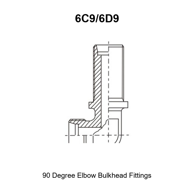
The fitting is a 90° elbow with metric male 24° cone ends (DIN 2353 / ISO 8434-1) arranged at a right angle, one leg running through a panel, bulkhead or bracket and clamped by a locknut. “C” (6C9) is the L (light) series; “D” (6D9) is the S (heavy) series.
Core Advantages
- One fitting, panel support and pressure containment. The tube run is anchored at the bulkhead instead of hanging on the end connections.
- Vibration isolation. The panel takes the mass of the tube run and the vibration that would otherwise be carried into the port threads.
- Clean service split. Tube runs can be disconnected on one side of the panel without disturbing anything on the other side.
- Full L and S series coverage. Tube 6 mm to 42 mm, L series to 31.5 MPa, S series to 63 MPa, all with 24° cone seats.
- Variant drawings in one family. The catalogue shows the plain 6C9/6D9, plus the -LN, -RN and -LN/RN versions of the same body for different clamping-nut and tube-end-nut arrangements, so one body family fits different panel constructions.
Technical Specifications
What Is a Bulkhead Elbow Adapter?
It is a 90° elbow whose body passes through a panel or bulkhead and is clamped on the far side by a locknut. Both connections are metric male 24° cone ends. The fluid flows through the body only — the panel joint is a mechanical clamp, not a pressure seal, which is why the panel itself does not have to be a sealing surface and can be any clean, square, adequately strong material.
Connection 1 and Connection 2 — Metric Male 24° Cone
Both ends are metric male studs with external 24° cones per DIN 2353 / ISO 8434-1 and 6g metric threads. In 6C9 the thread follows the L (light) series — M12×1.5 for 6 mm tube up to M52×2 for 42 mm. In 6D9 the same tube sizes use the S (heavy) series thread, one size larger — M14×1.5 for 6 mm tube up to M52×2 for 38 mm.
The 24° cone is metal-to-metal and needs no sealant. It does not interchange with a 60° cone (BSP, DIN 3861 / ISO 1179) or a 37° flare (JIC, ISO 8434-2); the three systems differ in included angle and contact diameter, and a cross-assembled joint typically passes a static test and then weeps at temperature.
Dimensional Data
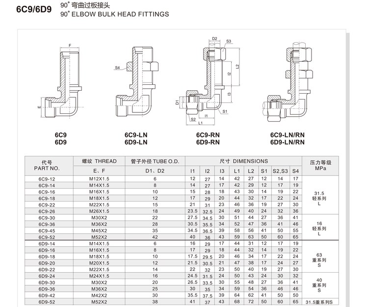
In the drawing, E and F are the threads of the two ends, D1 and D2 the tube outside diameters, l1 the stud reach on the tube leg, l2 and l3 the two panel-side stem dimensions, L1 and L2 the overall leg lengths, S1 the body hex, S2/S3 the end hexes and S4 the bulkhead locknut hex.
The two leg dimensions L1 and L2 lie on perpendicular axes and are not interchangeable: on a bulkhead elbow, rotating the body to change the flow direction also rotates the panel clamping face relative to the tube run. Confirm both the length direction and the height direction of your installation drawing, plus the panel thickness against l2 and l3, before ordering.
Dimension columns below follow the order printed in the HENGHUA catalogue drawing (l1, l2, l3, L1, L2, S1, S2/S3, S4). Confirm the leg assignment against the drawing if you are machining the panel hole from these figures.
Full Dimension Table (Part Number Matrix)
Values as published in the HENGHUA catalogue drawing. Dimensions in millimetres.
| PART NO. | THREAD E, F | D1, D2 | l1 | l2 | l3 | L1 | L2 | S1 | S2, S3 | S4 | Pressure MPa |
|---|---|---|---|---|---|---|---|---|---|---|---|
| 6C9-12 | M12×1.5 | 6 | 12 | 27 | 14 | 42 | 27 | 12 | 14 | 17 | 31.5 — L series |
| 6C9-14 | M14×1.5 | 8 | 14 | 27 | 17 | 42 | 29 | 12 | 17 | 19 | 31.5 — L series |
| 6C9-16 | M16×1.5 | 10 | 15 | 28 | 18 | 43 | 30 | 14 | 19 | 22 | 31.5 — L series |
| 6C9-18 | M18×1.5 | 12 | 17 | 29 | 20 | 44 | 32 | 17 | 22 | 24 | 31.5 — L series |
| 6C9-22 | M22×1.5 | 15 | 21 | 31 | 23 | 46 | 36 | 19 | 27 | 30 | 31.5 — L series |
| 6C9-26 | M26×1.5 | 18 | 23.5 | 32.5 | 24 | 49 | 40 | 24 | 32 | 36 | 31.5 — L series |
| 6C9-30 | M30×2 | 22 | 27.5 | 34.5 | 30 | 51 | 44 | 27 | 36 | 41 | 31.5 — L series |
| 6C9-36 | M36×2 | 28 | 30.5 | 35.5 | 34 | 52 | 47 | 36 | 41 | 46 | 16 — L series |
| 6C9-45 | M45×2 | 35 | 34.5 | 36.5 | 39 | 58 | 56 | 41 | 50 | 55 | 16 — L series |
| 6C9-52 | M52×2 | 42 | 40 | 36 | 43 | 59 | 63 | 50 | 60 | 65 | 16 — L series |
| 6D9-14 | M14×1.5 | 6 | 16 | 29 | 17 | 44 | 31 | 12 | 17 | 19 | 63 — S series |
| 6D9-16 | M16×1.5 | 8 | 17 | 29 | 18 | 44 | 32 | 14 | 19 | 22 | 63 — S series |
| 6D9-18 | M18×1.5 | 10 | 17.5 | 29.5 | 20 | 46 | 34 | 17 | 22 | 24 | 63 — S series |
| 6D9-20 | M20×1.5 | 12 | 21.5 | 30.5 | 21 | 47 | 38 | 17 | 24 | 27 | 63 — S series |
| 6D9-22 | M22×1.5 | 14 | 22 | 32 | 23 | 50 | 40 | 19 | 27 | 30 | 63 — S series |
| 6D9-24 | M24×1.5 | 16 | 24.5 | 31.5 | 24 | 50 | 43 | 24 | 30 | 32 | 63 — S series |
| 6D9-30 | M30×2 | 20 | 26.5 | 33.5 | 30 | 55 | 48 | 27 | 36 | 41 | 40 — S series |
| 6D9-36 | M36×2 | 25 | 30 | 35 | 34 | 59 | 54 | 36 | 46 | 46 | 40 — S series |
| 6D9-42 | M42×2 | 30 | 35.5 | 37.5 | 39 | 64 | 62 | 41 | 50 | 50 | 40 — S series |
| 6D9-52 | M52×2 | 38 | 41 | 37 | 43 | 68 | 72 | 50 | 60 | 65 | 31.5 — S series |
Thread Size and Dash Chart
| Tube OD (D1, D2) | L series (6C9) thread | S series (6D9) thread |
|---|---|---|
| 6 mm | M12×1.5 | M14×1.5 |
| 8 mm | M14×1.5 | M16×1.5 |
| 10 mm | M16×1.5 | M18×1.5 |
| 12 mm | M18×1.5 | M20×1.5 |
| 14 mm | — | M22×1.5 |
| 15 mm | M22×1.5 | — |
| 16 mm | — | M24×1.5 |
| 18 mm | M26×1.5 | — |
| 20 mm | — | M30×2 |
| 22 mm | M30×2 | — |
| 25 mm | — | M36×2 |
| 28 mm | M36×2 | — |
| 30 mm | — | M42×2 |
| 35 mm | M45×2 | — |
| 38 mm | — | M52×2 |
| 42 mm | M52×2 | — |
Material and Heat Treatment
Carbon steel bodies forged or machined from bar, hardened according to pressure class, plated in trivalent chromium or zinc-nickel, with the locknut plated in the same batch. Stainless 304 / 316L is available to order. Where the panel is aluminium or a composite, an insulating washer can be supplied to avoid galvanic contact with a steel panel.
Working Pressure and Operating Envelope
The pressure column is the working pressure of the L or S series connection, not a burst pressure; a 4:1 burst ratio is typical of the body. The bulkhead thread is a mechanical joint — it does not reduce the pressure rating, but the panel must be strong and square enough to take the clamping load and the tube run’s vibration without deforming.
Temperature Range
−40 °C to +120 °C for standard components; up to +200 °C with FKM seals in associated parts. The plate or washer material at the panel interface should be selected for the same temperature band.
How to Read the Part Number Matrix
6C9-12 reads: family 6C9 (90° bulkhead elbow, L series), size 12 = 6 mm tube / M12×1.5 at both ends. 6D9-14 is the S series equivalent — 6 mm tube, M14×1.5. The -LN, -RN and -LN/RN suffixes shown in the drawing denote the clamping-nut and tube-end-nut arrangements of the same body; state the exact variant when cross-referencing an OEM number.
Selection and Ordering
Selection Checklist / Decision Table
| Requirement | Choose |
|---|---|
| Tube run must pass through a panel or bulkhead | This family |
| Standard pressure, tube 6–22 mm | 6C9 (L series) |
| High pressure / heavy wall tube | 6D9 (S series) |
| Panel is thin and the nut run-out is tight | Check l2 against panel thickness, or use the -LN variant |
| Tube end must be a swivel nut | -RN variant of the same body |
| No panel, simple right angle | 1C9/1D9 elbow |
Cross Reference Service
Send the OEM number, the tube OD, the panel thickness and a photo of the assembly. We verify the stem length against the panel and return a mapped part number with l2/l3 confirmed and the correct locknut listed.
Packaging and Logistics
Locknut supplied fitted. Thread protectors, plastic bags, cartons and pallets; the panel thread is protected in transit because a dented bulkhead thread cannot be repaired on site. Certificates and inspection reports referenced to the heat number.
Installation and Fitment Guide
Step-by-Step Assembly
- Verify the panel hole diameter against the bulkhead thread, and the panel thickness against the l2/l3 stem dimensions. Deburr both sides of the hole.
- Check the panel is square and rigid. A flexible panel will move the tube run and load the tube ends.
- Insert the elbow through the hole from the working side.
- Fit the washer (and insulating washer where required) and run the locknut on by hand.
- Set the elbow’s flow direction first — once the nut is tight, the body position is fixed.
- Hold the body with the S1 hex and tighten the locknut to its specified torque. For long stems, a second nut can be used as a jam nut to set the stand-off.
- Fit the two tube connections and torque each 24° cone joint with a wrench on the body so the panel clamping load is not disturbed.
- Re-check nut torque after the first thermal cycle and after any maintenance on the panel.
Torque and Sealing Notes
The locknut torque is a clamping value, not a sealing value. It must be enough to hold the body against vibration and not so high that it crushes the panel or stretches the stem thread. A washer distributes the clamp load and protects the panel face. The two 24° cone joints are separate torqued joints with separate values; neither uses sealant or tape.
Installation Warnings
- Never tighten the locknut by turning the body or the tube connections; hold the body hex.
- Do not use the bulkhead joint as a pressure seal or expect it to seal a worn panel surface.
- Do not mix 24°, 60° and 37° cone components.
- Do not shorten the stem or add a spacer that reduces thread engagement below the specified number of turns.
- Do not overtighten on aluminium or composite panels without a load-spreading washer.
Applications and Industries
Bulkhead elbows are standard on mobile and off-highway machines where tubes cross a chassis member, on machine-tool cabinets and guarding, on hydraulic power units with panel-mounted manifolds, on shipboard systems where pipes pass bulkheads, on agricultural equipment, cranes and mining machinery, and on test benches where the tube run must be fixed relative to the instrumentation. The 90 degree elbow bulkhead fittings adapter is the part that turns a loose tube run into a supported one.
OEM Customization and Quality Traceability
Custom stem lengths, panel threads, washer and locknut combinations, special hex, alternative materials and plating are produced to drawing. Incoming material verification, first-article inspection, ring-gauge checks on the panel thread, squareness checks on the clamping face, proof pressure testing on sample lots and final inspection are recorded against the order, with EN 10204 3.1 certificates on request.
FAQ
Does the bulkhead joint seal the pressure? No. The fluid path is inside the body; the locknut only clamps the body to the panel.
What panel hole do I need? One sized to the bulkhead thread of the part number ordered, with the panel thickness within the stem dimensions l2/l3.
Can I use two locknuts? Yes, sometimes as a jam nut to set a stand-off from the panel, subject to keeping full thread engagement.
Is a washer needed? Recommended on soft panels and on aluminium to spread the clamp load and avoid galvanic contact.
6C9 or 6D9? Same geometry, different series — L (light) for 6C9, S (heavy) for 6D9.
Can the elbow be re-oriented after tightening? Only by releasing the locknut. Set the flow direction before final torque.
Request a Quote
Send the part number, the tube OD, the panel thickness and material, the quantity and the working pressure. We will confirm the stem length, the locknut and the washer, and quote with the inspection documentation included.
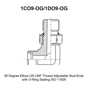
Related products in this range: straight bulkhead fittings adapter 6C/6D · 90° elbow fittings adapter 1C9/1D9 · 90° elbow reducer tube adaptor with swivel nut 2C9/2D9 · 90° elbow UN/UNF adjustable stud ends 1CO9-OG/1DO9-OG · equal tees AC/AD.
Browse the full Hydraulic Adapters range for the complete family, or contact us to request a quote, mill test reports, and samples.


 English
  Spanish
  Portuguese
  French
  German