
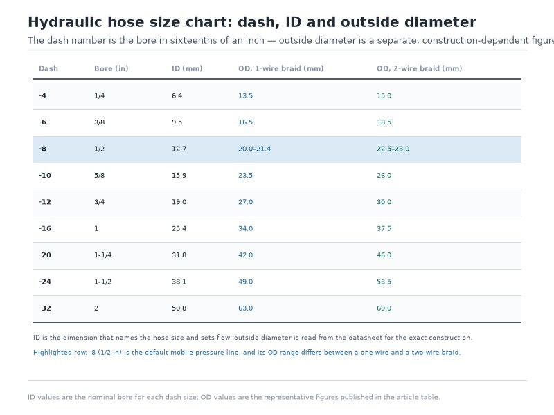
Hydraulic hose sizes are written as a dash number that states the hose inside diameter in sixteenths of an inch, so a -6 hose has a 6/16 inch (3/8 inch, 9.53 mm) bore. The outside diameter is a different number entirely and is set by the hose construction, not by the size number.
At the same -6 size, an outside diameter of roughly 18.1 mm belongs to a single-wire-braid hose, about 19.7 mm to a two-wire-braid hose, and 20.6 to 22.2 mm to a four-spiral hose. This guide sets out what ID, OD and dash size each mean, the same sizes in mm and in inches side by side, the method for measuring an unmarked hose with calipers in four steps, the hoses where the dash number is not the ID in sixteenths at all, the common sizes and how they pair with hydraulic hose fittings, and how hydraulic pipe sizes differ from hose sizes, so the line you order is the line that fits.
The Short Answer: Hydraulic Hose Size Is ID, and Dash Size Is ID in Sixteenths
Hydraulic hose size always refers to the inside diameter, never the outside diameter. The dash number is that inside diameter expressed in sixteenths of an inch, which is why the formula is simply dash size ÷ 16 = hose size in inches. A -4 hose is 4/16 inch (1/4 inch), a -8 hose is 8/16 inch (1/2 inch), and a -12 hose is 12/16 inch (3/4 inch). The outside diameter is determined by how the hose is built, not by its size number, so two hoses with an identical -8 dash number can differ by about 5 mm in outside diameter.
Three rules resolve almost every sizing question:
- Dash size gives the ID. Multiply the dash number by 1/16 inch to get the nominal bore, then by 25.4 to get millimetres.
- OD is construction-dependent. Heavier reinforcement and a thicker cover increase the OD at the same ID, which matters for clamps, bulkheads and routing.
- ID sets flow, OD sets fit. Choose the ID from the flow rate and velocity you need; choose the OD to confirm the hose actually passes through the space and hardware it has to occupy.
Everything below expands those three rules into the charts, measurement steps and conversions you need at the bench or at the quotation stage.
What Is Hydraulic Hose Dash Size and Where Did It Come From?
A hydraulic hose dash size is an industry shorthand that expresses the bore in sixteenths of an inch as a minus sign followed by a number. The system exists because hydraulic hose is sold, crimped and stocked as an assembly: the same dash number governs the hose bore, the mating ferrule, the fitting and the crimp die, so a single two-digit code carries an entire bill of materials. That is why hydraulic hose sizes are quoted, stocked and cross-referenced by dash number rather than by a millimetre dimension. Once you can read the dash number you can identify a hose, a fitting or a crimp specification without a catalogue.
The convention also draws a line between two families of product that look similar in a parts bin:
Table 1. What a dash number measures depends on the product: hoses are sized by bore, tubes and tube fittings by outside diameter, and a fitting end connection by the port it mates with.
| Product | What the dash number measures | Example |
|---|---|---|
| Hydraulic hose | Inside diameter, in sixteenths of an inch | -6 hose = 6/16 in (3/8 in) bore |
| Tube, and JIC/AN tube fittings | Outside diameter, in sixteenths of an inch | -6 JIC fitting = 6/16 in (3/8 in) tube OD |
| Fitting end connection | The port or thread it connects to, not the hose | A 10343-8-6 fitting has a -8 end connection on a -6 hose |
That third row is the most common source of ordering errors in our experience: a part number such as 10343-8-6 reads left to right as the fitting series, the end-connection size and the hose size, so the -8 tells you nothing about the hose it crimps onto.
How to Convert Dash Size to Inches and Millimetres
Converting a dash size is arithmetic, and it is worth doing by hand once so you trust it. Multiply the dash number by 1/16 inch to get the nominal bore in inches, then multiply by 25.4 to reach millimetres.
- Dash -4 → 4 ÷ 16 = 1/4 in → 0.25 × 25.4 = 6.35 mm
- Dash -6 → 6 ÷ 16 = 3/8 in → 0.375 × 25.4 = 9.53 mm
- Dash -8 → 8 ÷ 16 = 1/2 in → 0.5 × 25.4 = 12.7 mm
- Dash -12 → 12 ÷ 16 = 3/4 in → 0.75 × 25.4 = 19.05 mm
- Dash -16 → 16 ÷ 16 = 1 in → 1.0 × 25.4 = 25.4 mm
Note what the arithmetic produces: 3/8 inch converts to 9.53 mm, but catalogue columns and hose laylines commonly print 10 mm, and 1/2 inch converts to 12.7 mm while the printed figure is often 12.5 mm. Both numbers are correct because they answer different questions — 9.53 mm is the exact arithmetic equivalent of the inch bore, while 10 mm is the nominal metric size, called DN10, that the hose is catalogued under. Treat the two as a naming system, not as measurements, and order by the dash size or the DN size rather than by a millimetre figure you calculated.
How Do You Convert Hydraulic Hose Dash Size to ID in Inches and Millimetres?
Table 2 is the main hydraulic hose size reference our own sales and engineering teams work from, covering the full dash range from -3 through -40. It states the hydraulic hose inside diameter twice, once as the inch fraction that appears on the layline and once as the exact millimetre equivalent you can check against a drawing, and it adds the metric DN size that the same hose is ordered under in metric markets.
Table 2. Hydraulic hose sizes: dash size to ID in inches, exact millimetres and metric DN size. The millimetre column is the arithmetic equivalent of the inch fraction (dash divided by 16, multiplied by 25.4), which is why it sits a fraction of a millimetre away from the DN nominal bore; the rounder catalogue figures of 9.5 mm and 19.1 mm are the same sizes rounded to 0.1 mm.
| Strichstärke | ID (inches) | ID (mm, exact) | DN size | Typical use |
|---|---|---|---|---|
| -3 | 3/16 | 4.76 | DN 5 | Instrumentation, small pilot lines |
| -4 | 1/4 | 6.35 | DN 6 | Pilot and control lines, hydraulic tools |
| -5 | 5/16 | 7.94 | DN 8 | Low-flow power steering and lube lines |
| -6 | 3/8 | 9.53 | DN 10 | Medium-flow pressure lines, tractors, loaders |
| -8 | 1/2 | 12.70 | DN 12 | The most common mobile-equipment pressure line |
| -10 | 5/8 | 15.88 | DN 16 | High-flow pressure and return lines |
| -12 | 3/4 | 19.05 | DN 19 | Excavator mains, industrial power packs |
| -16 | 1 | 25.40 | DN 25 | Heavy industrial hydraulics, presses |
| -20 | 1-1/4 | 31.75 | DN 31 | Large return and suction-to-pump lines |
| -24 | 1-1/2 | 38.10 | DN 38 | Bulk transfer, marine and offshore deck lines |
| -32 | 2 | 50.80 | DN 51 | High-volume manifold and return lines |
| -40 | 2-1/2 | 63.50 | DN 63 | Large suction and return hose |
In the -20 row, some catalogues write the metric designation as DN 32 instead of DN 31; both labels refer to the same 1-1/4 inch bore, so check the nominal bore in millimetres rather than the label alone.
Nominal Size Is Not the Size You Will Measure
A hydraulic hose inside diameter is a nominal figure with a manufacturing tolerance, and the tolerance is wide enough to matter when you are deciding whether a measured hose is the size you think it is. In the EN 853 1SN/2SN and SAE 100R1/100R2 dimension classes the permitted bore range is about 0.8 mm wide on sizes -3 to -6 and widens to 1.2 mm from -8 upward. A 1/2 inch hose, nominally 12.7 mm, is therefore acceptable anywhere between 12.3 mm and 13.5 mm, a band of -0.4 / +0.8 mm about the nominal figure, and a hose that has been in service can exceed that band through swelling or permanent deformation.
The word “exact” therefore has to be defined before a millimetre figure is traded: 12.7 mm is the nominal bore, 12.3 to 13.5 mm is the permitted as-manufactured range, and only the range is something a caliper can verify.
Table 3. Nominal bore versus the permitted as-manufactured ID range for wire-braid hydraulic hose in the EN 853 1SN/2SN and SAE 100R1/100R2 dimension classes. The families are equivalent in construction but each publishes its own figures, so confirm the tolerance against the standard named on your order. Covers -3 through -32; the -40 size is listed in Table 2.
| Strichstärke | Nominal ID (mm) | Permitted ID range (mm) | Tolerance band (mm) |
|---|---|---|---|
| -3 | 4.8 | 4.6 – 5.4 | 0.8 |
| -4 | 6.4 | 6.2 – 7.0 | 0.8 |
| -5 | 7.9 | 7.7 – 8.5 | 0.8 |
| -6 | 9.5 | 9.3 – 10.1 | 0.8 |
| -8 | 12.7 | 12.3 – 13.5 | 1.2 |
| -10 | 15.9 | 15.5 – 16.7 | 1.2 |
| -12 | 19.1 | 18.6 – 19.8 | 1.2 |
| -16 | 25.4 | 25.0 – 26.4 | 1.4 |
| -20 | 31.8 | 31.4 – 33.0 | 1.6 |
| -24 | 38.1 | 37.7 – 39.3 | 1.6 |
| -32 | 50.8 | 50.4 – 52.0 | 1.6 |
This is why measuring a hose with a tape measure and comparing it against a chart so often produces a false answer. If your measured bore lands inside the band for one size and outside every other band, the size is confirmed. If it lands between two bands, the hose is worn, swollen or not a wire-braid construction, and the correct next step is to read the layline rather than to guess.
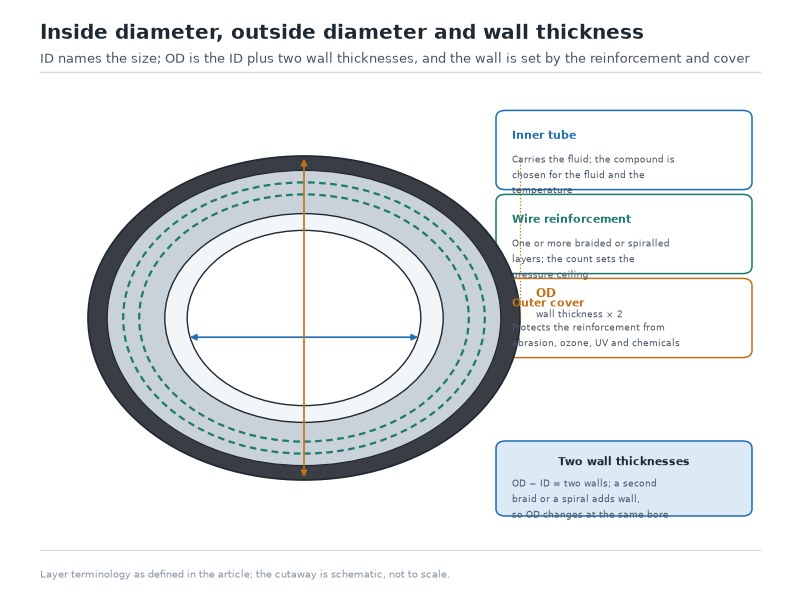
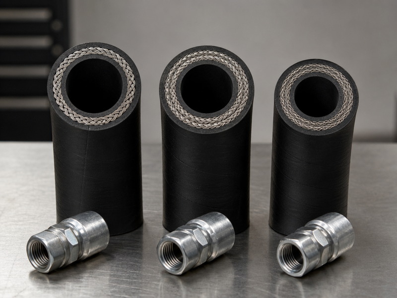
Figure 1. The hydraulic hose inside diameter (ID) is the dimension that names the size, while the outside diameter (OD) is the ID plus two wall thicknesses, and the wall thickness is set by the number of reinforcement layers and the cover compound — which is why OD changes between constructions at an identical dash size.
Why Does Hydraulic Hose Outside Diameter Change When the ID Does Not?
Hydraulic hose sizes are not a single number: the bore is fixed by the dash size, but the outside diameter depends entirely on how the hose is reinforced. Hydraulic hose outside diameter is set by the ID plus twice the wall thickness, and the wall thickness is dominated by how many layers of reinforcement the hose carries. Add a second wire braid and the OD grows by roughly 1.6 mm across the small and medium sizes (1.7 to 2.5 mm at -8 and -10, where the published bands are wider); move from two braids to a four-spiral construction and it grows again. The ID is unchanged in every case, so a table that lists one “typical OD” per dash size cannot answer a clearance question.
Table 4. Outside diameter at identical dash sizes, by construction. ID ranges are the permitted as-manufactured bore; OD figures are the published maximum or range for each standard family, and they are not a fixed standard requirement for the dash size itself, so the OD of a hose you are about to order should be confirmed on the datasheet for that exact family and dash size. Covers -3 through -32; the -40 size is listed in Table 2.
| Strichstärke | Hose ID | Single wire braid (1SN / 100R1): OD | Double wire braid (2SN / 100R2): OD | Four-spiral (4SP / 100R12): OD |
|---|---|---|---|---|
| -3 | 3/16 in (4.8 mm) | 12.5 mm | 14.1 mm | Not made |
| -4 | 1/4 in (6.4 mm) | 14.1 mm | 15.7 mm | Not made |
| -5 | 5/16 in (7.9 mm) | 15.7 mm | 17.3 mm | Not made |
| -6 | 3/8 in (9.5 mm) | 18.1 mm | 19.7 mm | 20.6 – 22.2 mm |
| -8 | 1/2 in (12.7 mm) | 20.0–21.4 mm | 22.5–23.0 mm | 23.8–25.4 mm |
| -10 | 5/8 in (15.9 mm) | 24.5 mm | 26.2 mm | 27.4 – 29.0 mm |
| -12 | 3/4 in (19.1 mm) | 28.5 mm | 30.1 mm | 31.4 – 33.0 mm |
| -16 | 1 in (25.4 mm) | 36.6 mm | 38.9 mm | 38.5 – 40.9 mm |
| -20 | 1-1/4 in (31.8 mm) | 44.8 mm | 49.5 mm | 49.2 – 52.4 mm |
| -24 | 1-1/2 in (38.1 mm) | 52.1 mm | 55.9 mm | 55.6 – 58.8 mm |
| -32 | 2 in (50.8 mm) | 65.5 mm | 68.6 mm | 68.2 – 71.4 mm |
If you are still deciding between braided, spiral, textile and thermoplastic constructions, the types of hydraulic hose guide covers how each family is built and where it belongs. Read the -8 row of Table 4 as a worked example: three hoses that all measure 1/2 inch at the bore run from 20.0–21.4 mm, from 22.5–23.0 mm and from 23.8–25.4 mm across the outside, a spread of about 5 mm.
Five millimetres is the difference between a hose that passes through a 24 mm bulkhead grommet and one that does not, and it is the difference between a standard clamp and one that crushes the cover. Whenever clearance, clamp size, bend radius or bundle diameter is on the drawing, specify the hydraulic hose outside diameter from the construction you actually intend to buy, and check the published figures for that family on the complete hydraulic hose size chart before the order is placed.
What Each Layer Adds to the OD
Working from the bore outward explains the numbers in Table 4 and lets you estimate an OD for a hose that is not in front of you:
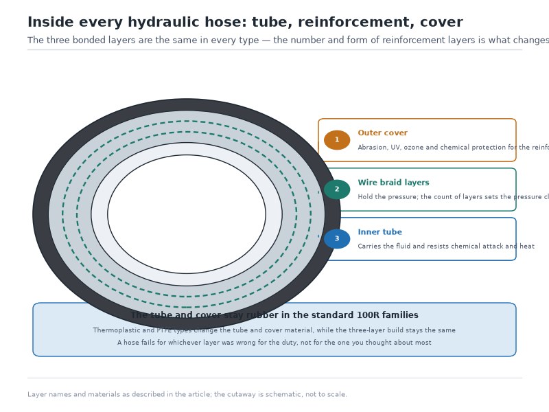
- Inner tube. Typically 1.5 to 2.5 mm of wall. Oil-resistant synthetic rubber in the 100R1/100R2 rubber families, polyamide in thermoplastic hose, PTFE in 100R14.
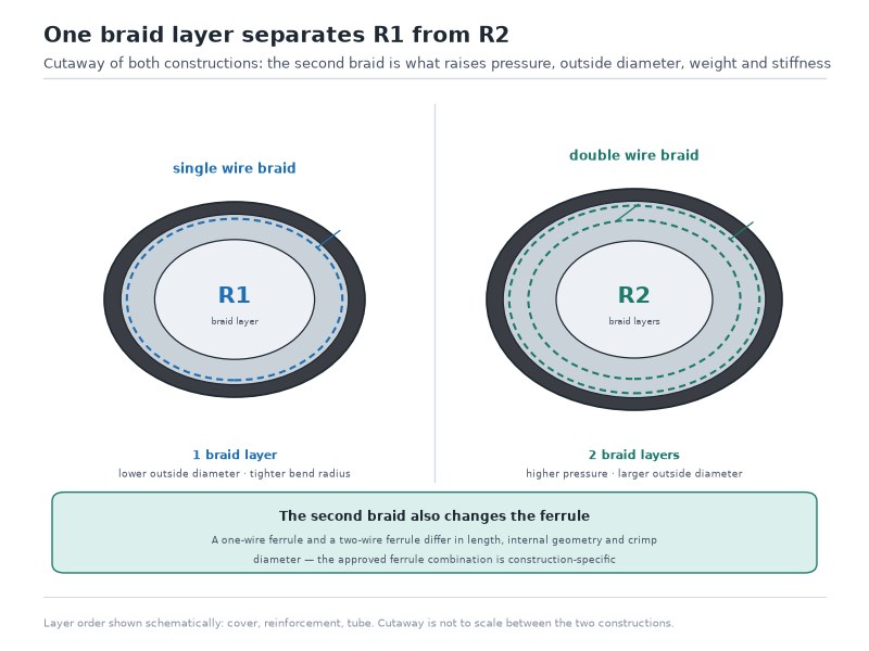
- Reinforcement. One braid of high-tensile steel wire adds about 1.6 mm to the finished diameter on most sizes, the same step that separates a single wire braid 1SN hose from a double wire braid 2SN hose at the same dash size, and 1.7 to 2.5 mm at -8 and -10 where the published bands are wider. A second braid layer adds another 1.6 mm on top of that. Four or six spiral layers add more again and are wound at a shallower angle, which is why spiral hose is both thicker and stiffer.
- Cover. Another 1.5 to 2.5 mm, and this is the layer that varies most between products. An abrasion-resistant or MSHA-accepted cover is thicker than a standard cover on the same reinforcement, and a wrapped (cloth-impression) cover measures slightly differently from a smooth cover.
Where the Dash Number Is Not the ID in Sixteenths
Two hydraulic hose families break the rule, and they are the exceptions that catch out experienced buyers as well as new ones. In SAE 100R5 (the textile-braid-wrapped, wire-reinforced hose used widely on trucks, buses and off-highway steering and transmission lines) and in SAE 100R14 (PTFE hose), the dash number refers to a diameter that is close to the hose’s outside diameter in sixteenths, so the actual bore is one size smaller than the number suggests. SAE J51 and SAE J2064 refrigerant hose follow the same convention. Our own SAE 100R14 PTFE hose is built to that convention, so its dash size is not a bore in sixteenths and should be cross-checked against Table 5 before it is quoted against an inch-bore circuit.
Table 5. Dash size versus actual inside diameter for standard hydraulic hose and for the SAE 100R5, 100R14, J51 and J2064 exception families. The exception families run to -48, while standard wire-braid hose is catalogued to -40, which is where the main size table above ends.
| Strichstärke | Standard hydraulic hose ID | SAE 100R5 / 100R14 / refrigerant hose ID |
|---|---|---|
| -4 | 1/4 in (6.4 mm) | 3/16 in (4.8 mm) |
| -5 | 5/16 in (7.9 mm) | 1/4 in (6.4 mm) |
| -6 | 3/8 in (9.5 mm) | 5/16 in (7.9 mm) |
| -8 | 1/2 in (12.7 mm) | 13/32 in (10.3 mm) |
| -10 | 5/8 in (15.9 mm) | 1/2 in (12.7 mm) |
| -12 | 3/4 in (19.1 mm) | 5/8 in (15.9 mm) |
| -16 | 1 in (25.4 mm) | 7/8 in (22.2 mm) |
| -20 | 1-1/4 in (31.8 mm) | 1-1/8 in (28.6 mm) |
| -24 | 1-1/2 in (38.1 mm) | 1-3/8 in (34.9 mm) |
| -32 | 2 in (50.8 mm) | 1-13/16 in (46.0 mm) |
| -40 | 2-1/2 in (63.5 mm) | 2-3/8 in (60.3 mm) |
| -48 | Not made | 3 in (76 mm) |
In SAE 100R5 and SAE 100R14 a -8 hose carries about a third less flow area than a standard -8, because its bore is roughly 10 mm instead of 12.7 mm. When a customer sends us a -8 truck steering hose to duplicate and asks for “half-inch”, we confirm the family before quoting, because the bore of that hose is 10 mm and a standard -8 hose with a 12.7 mm bore is a different part.
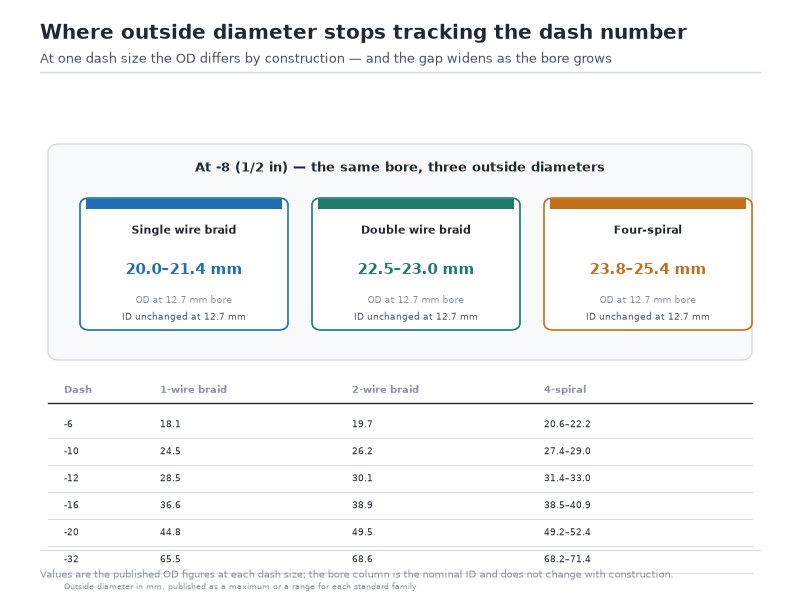
Figure 2. ID stays constant across constructions at a given dash size while OD steps up with each reinforcement layer. A -8 bore of 1/2 inch measures 20.0–21.4 mm on the outside as a single-braid hose, 22.5–23.0 mm as a double-braid hose and 23.8–25.4 mm as a four-spiral hose.
How to Measure Hydraulic Hose Size: ID, OD and Length in Four Steps
Establishing the hydraulic hose diameter and the assembly length correctly comes down to four measurements taken in a fixed order, because each one can save you from the next. How to measure hydraulic hose size is therefore a sequence rather than a single reading. Read the layline first, measure the inside diameter second, measure the outside diameter third, and measure the overall length last — including the fittings. The whole sequence takes under two minutes with a caliper and a tape, and because hydraulic hose sizes are the one thing a supplier cannot infer from a photograph, it is the difference between a first-time fit and a second shipment.
Step 1: Read the Layline Before You Measure Anything
Every hydraulic hose made to a published standard carries a printed layline on the cover. In our production we print the standard family, the dash size, the working pressure, the quarter and year of manufacture and the batch code. The layline gives you the authoritative answers — standard family, dash size and pressure rating — in a single line, and it is the only measurement that cannot be affected by wear.
If the printing is legible, write down the standard family and dash size and treat them as final. If the printing has been polished off by abrasion, cut a clean section and measure as below, and add the missing pressure rating to the questions you ask your supplier.
Step 2: Measure the Hydraulic Hose Inside Diameter
The hydraulic hose inside diameter is the measurement that identifies the hose size, and it has to be taken on a square-cut end with the hose relaxed and straight.
- Cut a clean, square section about 25 mm long from a straight part of the hose, well away from any fitting or crushed area.
- Insert the internal jaws of a digital or dial caliper into the bore and open them until they just touch both walls. Do not force the jaws; rubber deflects, and forcing them reads high.
- Take three readings at roughly 120 degrees apart and record the average. Ovality is normal in a hose that has been under pressure or stored on a tight reel.
- Compare the average against the permitted ID range in Table 3 rather than against the nominal figure alone, because the band is what a caliper can actually verify.
If you do not have calipers, a set of tapered sizing dowels or a plug gauge will identify the size by trial, and a drill-shank of known diameter works in a workshop as a go/no-go check. Measure the bore with calipers or a sizing dowel set: a tape measure reads to roughly 1.5 mm on a -6 hose, which is the whole difference between a 9.53 mm bore and the 7.94 mm of the next size down.
Step 3: Measure the Outside Diameter
The outside diameter is the hydraulic hose diameter that decides whether the hose fits the machine. Measure across the cover with the external jaws of the caliper, at three points along a straight run rather than at the very end where the cover may be flared by the crimp collar.
Write the OD down and compare it against the construction you intend to order, using Table 4. An outside-diameter reading catches a mistake that no bore measurement can catch: an OEM that specified a two-braid hose for a given circuit because the clamp, the grommet or the bend radius was sized around a 22.5–23.0 mm cover. Substituting a four-spiral hose in the same dash size takes the outside diameter from 23.0 mm to as much as 25.4 mm, an increase of 0.8 to 2.4 mm, and can load the hose against a structure it was never routed to clear.
The hydraulic hose outside diameter confirms only the construction family, not the size: if the figure falls between two columns of Table 4 — a -6 double-braid cover at 19.7 mm against a -8 single-braid cover at 20.0 mm, for example — read the layline or measure the bore, because 0.3 mm of cover wear separates the two families.
Step 4: Measure Overall Length, Not Hose Length
Length is the measurement most often taken on the failed hose and quoted without qualification, and it is the one where the definition matters most. What a supplier needs is the overall length (OAL) — the distance from the sealing face of one end connection to the sealing face of the other — because that is what determines whether the assembly fits between two fixed ports.
- Straight fittings at both ends: measure from the seating face of one fitting to the seating face of the other.
- Angled fittings: measure from the centreline of the sealing face on each end, not from the outside of the bend.
- One straight, one angled: measure from the seating face of the straight fitting to the centreline of the angled fitting’s seating face.
- Elbows and ports: note the orientation of each angled end, in degrees, relative to the other. Two identical lengths with different clocking positions are two different assemblies.
Allow for the routing as well. A hose installed straight from port to port with no slack will pull on its fittings under pressure and vibration, while an over-long hose will kink, chafe and collect dirt. On mobile equipment we typically add a modest allowance for movement so the hose takes a gentle sweep rather than a straight line.
Send us the standard family or the layline text, the dash size, the working pressure and the overall length with the fitting orientation, and we will confirm the size, the metric DN equivalent and the matching ferrule before quoting.
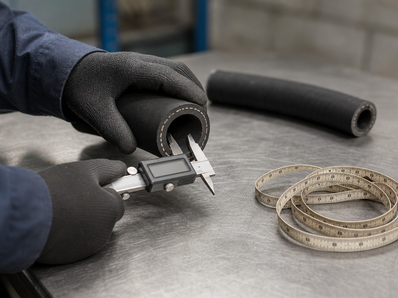
Figure 3. The bore is the hydraulic hose diameter reading that identifies the size, and how to measure hydraulic hose size starts with this reading. Measuring it on a square-cut section with digital calipers. Three readings at 120 degrees apart and a relaxed, straight sample give a repeatable result; forcing the jaws or measuring a crushed end does not.
Common Measuring Mistakes That Produce the Wrong Hose
When someone tells us they measured the hose themselves and the assembly still did not fit, one of these seven errors is almost always behind it. They are also the errors our technical desk sees most often when a customer asks how to measure hydraulic hose size and reaches the wrong answer:
- Measuring a hose still under pressure or still attached. Isolate and depressurise the line before you measure or cut; even a correctly isolated hose holds residual pressure that distorts both the bore and the length.
- Measuring the OD and assuming it is the size. An outside diameter of 22.5–23.0 mm is a -8 double-braid hose, but 23.8–25.4 mm is a -8 four-spiral hose with the same bore. Only the ID identifies the size.
- Measuring a swollen or collapsed hose. Heat, fluid exposure and age change the bore. If the layline is unreadable and the measured bore sits between two size bands, the hose is not a reliable sample.
- Measuring length as hose length and omitting the fittings. Overall length is measured from sealing face to sealing face, so a figure recorded as hose length alone comes out short by roughly the coupling length at each end — on a -8 assembly the two couplings together account for most of that difference.
- Ignoring fitting orientation. Recording a length without recording which way each elbow points guarantees a second order.
- Reading a nominal millimetre figure as a measurement. Read the catalogue millimetre figure as a name, not a dimension: 3/8 inch is 9.53 mm and the catalogue’s 10 mm is DN 10, so order by the dash size or the DN designation.
- Assuming every -8 is a half-inch bore. In SAE 100R5 and 100R14 the same dash number means roughly 10 mm.
How Do You Choose the Right Hose Size From Flow Rate?
The inside diameter is not chosen from a chart alone; it is chosen so that the fluid velocity inside the line stays within a sensible band for the duty. Velocity that is too high generates heat, noise and pressure loss; velocity that is too low means the hose is larger, heavier and more expensive than the circuit needs. The relationship is fixed arithmetic:
Velocity (ft/s) = GPM × 0.3208 ÷ internal area (in²)
Equivalently, v = 0.4085 × GPM ÷ d² with d in inches — the same relationship, written in the bore rather than in the area form, because 0.3208 ÷ (π ÷ 4) = 0.4085. The site’s sizing pages print the bore form rounded to 0.408; the two agree to three significant figures, a difference below 0.2%.
Table 6. Recommended fluid velocity by line function, from hydraulic system design practice rather than a fixed standard requirement. Values above the upper end convert flow energy into heat and pressure loss; values below the lower end waste hose diameter and cost.
| Line function | Typical pressure | Recommended velocity |
|---|---|---|
| Pump suction | Below atmospheric | 2 – 4 ft/s (0.6 – 1.2 m/s) |
| Return line | Under 100 psi | 10 – 15 ft/s (3.0 – 4.6 m/s) |
| Medium-pressure line | 500 – 2,000 psi | 15 – 20 ft/s (4.6 – 6.1 m/s) |
| High-pressure line | 2,100 – 5,000 psi | 20 – 25 ft/s (6.1 – 7.6 m/s) |
Applying that formula to nominal bores gives the flow capacity of each dash size. Table 7 is the one our engineers use when a customer sends a pump flow rate and asks which size to buy.
Table 7. Flow capacity for three reference dash sizes, calculated as Q = v × area ÷ 0.3208 using the nominal bore. Values assume a cylindrical bore and clean fluid; sizes outside these three are covered by the flow-rate sizing method in the hydraulic hose sizing from flow rate guide.
| Strichstärke | Nominal ID (in) | Internal area (in²) | GPM at 10 ft/s | GPM at 15 ft/s | GPM at 20 ft/s |
|---|---|---|---|---|---|
| -8 | 0.500 | 0.196 | 6.1 | 9.2 | 12.2 |
| -10 | 0.625 | 0.307 | 9.6 | 14.3 | 19.1 |
| -12 | 0.750 | 0.442 | 13.8 | 20.7 | 27.5 |
Two worked examples show how the numbers are used. A 16 gpm high-pressure line is sized against the conservative 20 ft/s ceiling we apply to high-pressure lines — the lower edge of the 20–25 ft/s band in Table 6 — and the first dash size that carries that flow inside the limit is -10: it passes 19.1 gpm at 20 ft/s, while the -8 row above caps out at 12.2 gpm.
A 10 gpm return line is sized against the 10–15 ft/s return band rather than the 20 ft/s ceiling: the -10 row passes 9.6 gpm at 10 ft/s and 14.3 gpm at 15 ft/s, so 10 gpm sits inside that band at about 10.5 ft/s. Pressure on a return line is a fraction of the supply line’s, but the bore still controls velocity and back pressure, so -10 stays the right answer.
These two examples become a full bore-selection method in the hydraulic hose sizing from flow rate guide, which starts from pump flow, adds pressure drop and heat, and returns a size for every line in the circuit.
Sizing a whole circuit is a wider job than picking a bore, and the hydraulic oil hose selection guide takes these same numbers through pressure, temperature, fluid and bend radius. One caveat belongs here, and it is a real limitation rather than a marketing point. Size from flow if the circuit is a new build, and size from the layline if you are replacing a hose. Where the two disagree, the layline wins unless a hydraulic engineer has signed off on the change, because the rest of the machine — pump inlet, valve ports, cooler capacity — was designed around the original bore. Enlarging a hose to reduce velocity pays back only if the downstream restriction is relieved at the same time.
How Do You Match Hydraulic Hose Dash Size to a Metric DN Size?
Metric markets catalogue the same hose under a DN size rather than a dash number, and the two systems are close but not identical. The ID (mm, exact) and DN size columns of Table 2 put them side by side. Because the DN series is a rounded nominal series while the dash number is an exact fraction, a dash size and its DN equivalent differ by a fraction of a millimetre on most sizes. The practical rule is to convert in one direction only: order the dash size when the machine came from an inch-based market and the DN size when the drawing is metric, and never substitute one for the other on the strength of a rounded millimetre figure.
The -6 size is the one that causes trouble. Its exact bore is 9.53 mm and its DN designation is DN 10, a 0.5 mm gap that is larger than on any other common size. A customer converting “10 mm hose” backwards to a dash number and ordering a -10 receives a hose with a 15.9 mm bore — a size and a half too large. This is one of the reasons we ask for the dash size or a photograph of the layline rather than a millimetre figure when a hose is being duplicated. Where the layline names an SAE family instead, the family number and the dash size are the first two items to check against that standard before any size is quoted.
Hydraulic Hose Sizes in mm and Inches: One Table, Two Systems
The same hose is sold under two naming systems, and the difference between them is a rounded name rather than a measured dimension. In an inch market the hose is ordered by dash size, so a -8 is a half-inch bore. In a metric market the same hose is ordered by its DN designation, which is the nominal bore rounded to the nearest catalogued step: -8 is DN 12, and the DN nominal bore is 12.5 mm rather than the arithmetic 12.70 mm. The millimetre and inch figures therefore differ in the second decimal place, and the DN label itself is a name rather than a dimension to measure against. Table 2 lists both columns for every size from -3 to -40.
Two consequences follow at the counter. Order in the system the machine was built to: a hose taken off a European machine is ordered as DN, one taken off a North American machine as dash, and the two are cross-referenced but never substituted on the strength of a rounded millimetre figure. Then quote the permitted bore range from Table 3 rather than the nominal figure when you are checking a hose you already hold, because a tolerance band 0.8 to 1.2 mm wide swallows the difference between the two naming systems on almost every size.
How Hydraulic Pipe Sizes Differ From Hose Sizes
Three dimensioning systems look alike in a catalogue and are not interchangeable. A pipe size is a nominal bore designation: the number in the callout refers to a historic nominal bore rather than to a dimension you can measure on the pipe, and the pipe’s outside diameter is set by its own wall schedule. A tube size is the outside diameter, measured on the part, with the bore following from the wall thickness.
A hose size is the inside diameter, and it is identified by the dash number rather than by a pipe designation. A nominal half-inch pipe and a -8 hose therefore have nothing dimensional in common, and neither will accept the other’s fittings. When a drawing mixes a pipe callout, a tube outside-diameter callout and a hose dash number, convert each one to the system it belongs to before ordering, and use the dash size only for the hose.
The Most Common Hose Sizes: Which Six Cover Most Machines
Six dash sizes cover the majority of mobile and industrial hose positions, and they are the ones worth holding in stock:
Table 8. Six hydraulic hose sizes that cover the majority of mobile and industrial hose positions, with the bore in both systems and the duty each one normally carries on loaders, excavators, presses and power packs. Bore in millimetres is the arithmetic equivalent (dash ÷ 16 × 25.4), the same convention as the ID (mm, exact) column of Table 2; the nominal figures in Tables 3 and 4 are those sizes rounded to 0.1 mm.
| Strichstärke | Bore (inch / mm) | Where it is normally used |
|---|---|---|
| -4 | 1/4 in / 6.35 mm | Pilot, gauge and control lines; hydraulic tools |
| -6 | 3/8 in / 9.53 mm | Power steering, small cylinders, tractor auxiliary lines |
| -8 | 1/2 in / 12.70 mm | The default pressure line on loaders, excavators and backhoes |
| -10 | 5/8 in / 15.88 mm | High-flow pressure lines and medium return lines |
| -12 | 3/4 in / 19.05 mm | Excavator mains, breaker lines, industrial power packs |
| -16 | 1 in / 25.40 mm | Main return lines, suction-to-pump lines, presses |
Non-metric buyers also ask for these sizes by number rather than by dash. In North American practice the digit is the dash number with the minus sign dropped, so an “#8 hydraulic hose” is a -8 with a half-inch bore; in a metric catalogue the same digit can be a DN size, where DN 8 is a 7.7 to 8.5 mm bore. Ask which convention a quote uses before the order is placed: a “6” is a -6 on one side of the Atlantic and DN 6 on the other, and the two bores are more than 3 mm apart.
How Does Hose Dash Size Match Fittings and Crimp Dies?
A hose dash size and its fitting share the same number, and the crimp specification is tied to the specific combination of hose family, dash size and fitting series. Three levels of size are in play on every assembly:
- Hose dash size — the bore, in sixteenths of an inch. A -8 hose is 1/2 inch bore.
- Fitting end-connection size — the port or thread the fitting connects to. It is usually the same dash number as the hose, but not always, and part numbers carry both; the hydraulic fitting types guide walks through the families you are most likely to meet.
- Ferrule and crimp die — matched to the hose family and dash size. A ferrule specified for a two-braid 2SN hose will not correctly crimp a four-spiral 4SP hose of the same dash size, because the cover diameter differs.
For JIC and AN connections, which are sized by tube outside diameter rather than hose bore, the thread callout is the one people actually need at the counter. Table 9 maps that range onto hose dash sizes; the full JIC, ORFS, NPTF and flange thread range sits with the fitting families themselves.
Table 9. JIC / AN end-connection thread and typical wrench size by dash size. These connections are sized by tube outside diameter, while the hose they attach to is sized by bore.
| Strichstärke | Tube OD (in) | Thread size | Threads per inch | Typical wrench (in) |
|---|---|---|---|---|
| -4 | 1/4 | 7/16-20 UNF | 20 | 9/16 |
| -5 | 5/16 | 1/2-20 UNF | 20 | 5/8 |
| -6 | 3/8 | 9/16-18 UNF | 18 | 3/4 |
| -8 | 1/2 | 3/4-16 UNF | 16 | 15/16 |
| -10 | 5/8 | 7/8-14 UNF | 14 | 1-1/8 |
| -12 | 3/4 | 1-1/16-12 UN | 12 | 1-5/16 |
| -16 | 1 | 1-5/16-12 UN | 12 | 1-5/8 |
| -20 | 1-1/4 | 1-5/8-12 UN | 12 | 1-7/8 |
Note how the thread size never equals the dash size: a -6 JIC connection uses a 9/16 inch thread on 3/8 inch tube. The thread series also changes as size grows: the 20, 18, 16 and 14 threads per inch of the smaller sizes give way to a 12-thread-pitch UN thread from -12 upward, which is why the last three rows are marked UN rather than UNF. Confirm both the dash size and the thread series on the fitting datasheet rather than inferring them, and treat the wrench column as typical rather than guaranteed — flat-to-flat dimensions vary between manufacturers.
Frequently Asked Questions
What does a hydraulic hose dash size mean?
A dash size is the hose inside diameter expressed in sixteenths of an inch, written as a minus sign and a number. A -6 hose has a 6/16 inch bore, which is 3/8 inch or 9.53 mm. The same number is used for the mating ferrule and fitting, which is why one code can specify a complete assembly.
Is a hydraulic hose measured by its inside diameter or its outside diameter?
By its inside diameter, because the dash number names the bore and the bore controls flow rate, velocity and pressure loss. The outside diameter is the number that decides whether the hose fits: clamps, bulkhead clearances, bend radius and bundle diameter are all sized around it, and at a single dash size it can move by about 5 mm between a single-braid and a four-spiral construction. Identify the size from the bore, then confirm the fit from the hydraulic hose diameter measured across the cover.
What are hydraulic hose sizes in mm and inches for the common sizes?
The common sizes run -4 at 1/4 inch or 6.35 mm, -6 at 3/8 inch or 9.53 mm, -8 at 1/2 inch or 12.70 mm, -10 at 5/8 inch or 15.88 mm, -12 at 3/4 inch or 19.05 mm, and -16 at 1 inch or 25.40 mm. Metric catalogues list the same hoses as DN 6, DN 10, DN 12, DN 16, DN 19 and DN 25, where the DN figure is a rounded nominal bore rather than the arithmetic millimetre equivalent. Order in the system the machine was built to and cross-reference the other one.
Why do two hoses with the same dash size have different outside diameters?
Because OD is the bore plus two wall thicknesses, and the wall thickness depends on the reinforcement and cover. A half-inch bore measures 20.0–21.4 mm on the outside as a single-braid hose, 22.5–23.0 mm as a double-braid hose and 23.8–25.4 mm as a four-spiral hose. The ID is identical in all three.
Are the hoses where dash size is not the ID common?
The sixteenths rule holds across the standard families. Four families are the exception — SAE 100R5, SAE 100R14, SAE J51 and SAE J2064 refrigerant hose — where the dash number relates to a diameter close to the hose outside diameter in sixteenths and the true bore is one size smaller. A -8 in these families is roughly 10 mm bore rather than 12.7 mm.
Which hose sizes and fittings go together at each dash size?
A hose dash size and its mating fitting usually carry the same number, but they measure different things. The hose number is a bore in sixteenths of an inch; a JIC or AN fitting end is a tube outside diameter, so a -6 fitting uses a 9/16 inch thread on 3/8 inch tube; and an ORFS, NPT or flange end is called out by its own port size. The ferrule and crimp die are matched to the combination of hose family, dash size and fitting series, so a ferrule specified for a two-braid 2SN hose will not correctly crimp a four-spiral 4SP hose of the same dash size. Give the supplier the family, the dash size and the end-connection type at each end.
What are the most common hydraulic hose sizes on mobile equipment?
The -8 and -12 sizes cover most pressure lines on loaders, excavators and backhoes, with -6 on steering and auxiliary circuits and -10 on high-flow pressure and return lines. The -4 size is the pilot, gauge and control size, and -16 appears on main return and suction-to-pump lines. The digit-only question, such as a “6 hydraulic hose” or an “#8 hydraulic hose”, refers to the dash number in North American practice and to the DN size in metric catalogues, so confirm which convention a quote uses.
How do hydraulic pipe sizes compare with hose sizes?
They are two different dimensioning systems and share no dimensions. A pipe size is a historic nominal bore and a tube size is an outside diameter; this guide sets both out under “How Hydraulic Pipe Sizes Differ From Hose Sizes”. A hose size is the inside diameter, and it is identified by the dash number. A nominal half-inch pipe and a -8 hose therefore have nothing dimensional in common, and neither will accept the other’s fittings.
Does hydraulic hose size affect pressure rating?
Yes. In every standard family the working pressure falls as the bore grows, because the same reinforcement carries a larger hoop load on a bigger diameter. In the EN 853 2SN family a -4 hose is rated 5,800 psi and a -24 hose 1,500 psi (103 bar). SAE J517 100R2AT is the equivalent American family, and the two standards publish different working pressures for the same dash size (100R2AT gives 5,000 psi at -4 and 1,250 psi at -24), so the standard has to be named on the order. Both standards specify a minimum burst pressure of four times the maximum working pressure (EN 853 / EN 857 / SAE J517), which is why the rating you order has to match the standard printed on the layline. The working pressure versus burst pressure guide sets out the size-by-size relationship. Picking the bore from flow and confirming the pressure rating for that size are two separate steps.
A used hose measures 13.2 mm at the bore – is it still a -8?
A -8 is permitted anywhere from 12.3 mm to 13.5 mm as manufactured, so 13.2 mm sits inside the band for a new hose. On a hose that has been in service the reading alone is not enough: heat, fluid exposure and age swell or compress the bore, and a worn -8 can read inside the band for -10. Read the layline if any of it survives, take three readings about 120 degrees apart rather than one, and where the layline is gone and the reading sits near a band edge, re-establish the size from the fitting or the machine’s parts list.
Can I confirm a hose size on site without a caliper?
A set of tapered sizing dowels or a plug gauge identifies the bore by trial, and a drill shank or a known bolt diameter works as a go/no-go check in a workshop. A tape measure is the one tool that will mislead you: it reads to about 1.5 mm on a -6 hose, which is the whole difference between a 9.53 mm bore and the 7.94 mm of the next size down. If nothing fits the bore cleanly, read the layline or photograph it and send the photo with the fitting details rather than working from a single reading.
How do I write a hose size into an enquiry or a drawing so it cannot be mis-read?
Name the standard family, then the dash size, then the bore in millimetres as a cross-check: “EN 853 2SN, -8, 12.7 mm bore, DN 12”. Add the working pressure at the relief valve, the fluid and temperature, the overall length from sealing face to sealing face, the fitting orientation in degrees, and the end-connection type and thread at each end. A millimetre figure on its own is the one thing a supplier cannot resolve for you, because a catalogue 10 mm may mean DN 10 or a -10 hose.
Final Verdict: Get the ID Right, Then Verify the OD and the Threads
Hydraulic hose sizes reduce to one governing number — the dash size, which is the inside diameter in sixteenths of an inch — plus two verifications that the number alone cannot cover. The inside diameter decides flow, velocity and pressure loss, and it is the dimension that identifies the hose. The outside diameter decides whether that hose physically fits, and it changes by several millimetres between constructions at the same dash size, so it has to be read from the construction you intend to buy rather than from a generic chart. The end connection decides whether the assembly connects, and for JIC and AN fittings the dash number refers to tube OD and a thread size that never matches the hose number.
Measure in the order this guide sets out: layline first, then bore, then outside diameter, then overall length with fitting orientation. Followed in that order, hydraulic hose sizes stop being a guessing game and become a short list of confirmed numbers. Where the layline is gone and the measured bore falls between two size bands, treat the hose as unidentified and re-establish the size from the fitting it came off or from the datasheet for that family.
HENGHUA manufactures hydraulic hose and crimped hose assemblies in the wire-braid and spiral families this guide covers — SAE 100R1AT and 100R2AT, DIN EN 853 1SN and 2SN, SAE 100R16 and 100R17 compact hose from 6 mm to 51 mm bore, SAE 100R12, 100R13 and 100R15, DIN EN 856 4SP and 4SH spiral from 10 mm to 51 mm, thermoplastic 100R7 and 100R8 from 3 mm to 25 mm, textile-braided 100R3 and 100R6 from 5 mm to 63 mm, and PTFE 100R14.
We mix our own rubber compounds, braid our own wire on German Mayer braiding machines held to ±0.05 mm, extrude, vulcanise and crimp in house, and proof-test every assembly before it ships, so the dimensional data on our specification sheets matches the hose in the box. Because the same facility produces the hose and the matching ferrule, we can confirm the correct ferrule and crimp diameter for the exact family and dash size you order rather than for a general size class. Our published bore and OD tolerance tables are drawn from the same production records we use for batch traceability, and test data can be supplied for the batch you receive.
Two limits are worth stating plainly. A hose size cannot be confirmed from an outside diameter measurement alone, and a bore change on an existing machine cannot be recommended without knowing the rest of the circuit.
What we can do is convert your layline, your caliper readings or your drawing into the correct dash size, DN size, ferrule and crimp, and quote hose or complete assemblies against all three. Send us the standard family, dash size, working pressure, overall length with fitting orientation, and the end connections at each end — or a photograph of the layline and the two ends — and our engineering team will confirm the size, the construction and the delivery date.
Request a quote and a size confirmation.
About the author. Written by the HENGHUA engineering team. This guide is maintained by the HENGHUA Engineering Team, the group responsible for hose specification, crimp validation and dimensional inspection across our manufacturing and quality operation. Between them the team covers rubber compounding, wire braiding and spiral winding, assembly crimping, and the burst and impulse testing that every batch passes before it is released. Questions on a specific size, tolerance or ferrule match are answered by the same team that sets the specifications.
Last updated:
Revision note (18 September 2026). The permitted-ID tolerance table and the exception-family table were added in this revision, outside-diameter values were re-checked against current EN 853 1SN/2SN and EN 856 4SP/4SH published data, and the dash-to-DN table was merged into the main size table so that inches, exact millimetres and DN appear in one place.
This page is re-checked against the current EN 853 1SN/2SN and EN 856 4SP/4SH published dimensional tables whenever those standards are revised, and whenever our own size catalogue changes; the revision date above is updated at the same time.
 English
  Spanish
  Portuguese
  French
  German
  Arabic
  Russian