
A hydraulic hose temperature rating is the range of fluid temperatures a hose is designed to carry continuously — for standard rubber hydraulic hose, -40°C to +100°C (-40°F to +212°F), with an intermittent allowance that usually stops around +120°C (+248°F).
The three limits people search for most often are these: standard rubber hose -40°C to +100°C, thermoplastic (100R7/100R8) -40°C to +93°C, and PTFE -54°C to +204°C, with a +120°C intermittent allowance on the standard rubber families.
Everything else about the rating follows from that base: which tube compound is used, how the cover behaves against external heat, how much the pressure rating must be derated above +100°C, and how fast the hose ages if you exceed the limit by even 10°C. This guide sets out the hydraulic hose temperature limit and the maximum temperature for every standard family in one chart, explains the difference between fluid, ambient and surface temperature, gives the derating you apply above the limit, and walks through the selection sequence — including the cold end of the range, protection options for a heat resistant hydraulic hose, the choice between a standard and a high temperature hydraulic hose, and the test data to ask a supplier for before you buy.
The Short Answer: Four Numbers Make Up One Temperature Rating
A hydraulic hose temperature rating is four separate limits that are often printed as one, and confusing them is the most common cause of a hose that fails early without ever seeing over-pressure:
Table 1. The four limits that make up a hydraulic hose temperature rating.
| Rating | What it describes | Typical value for standard rubber hydraulic hose | Where to find it |
|---|---|---|---|
| Continuous fluid temperature | The oil temperature inside the tube, sustained indefinitely | -40°C to +100°C (-40°F to +212°F) | Datasheet, standard family (SAE 100R1, 100R2, EN 853 2SN) |
| Intermittent fluid temperature | Short excursions, normally defined as up to about 10% of operating time | +120°C (+248°F) | Datasheet footnote |
| Ambient temperature | The air temperature around the hose, which affects heat dissipation | -40°C to +100°C, cover-dependent | Cover compound specification |
| External / surface exposure | Radiant or contact heat on the outer cover | Depends on cover and any protective sleeve fitted | Cover specification and installation review |
The continuous fluid temperature limit governs hose selection, while the intermittent, ambient and surface limits decide whether the hose actually reaches the end of its rated life, because a hose whose fluid runs at 90°C but whose cover sits 100 mm from an exhaust manifold is being asked to perform in a different thermal environment from the one its datasheet describes.
Two industry rules of thumb shape how much margin is worth buying:
- A hose run 10°C above its recommended maximum can lose roughly half of its expected service life — a hose-maker rule of thumb rather than a standard requirement or a measured curve for your machine.
- The same 10°C overshoot can cut seal life by 80 percent or more — a seal-vendor rule of thumb rather than a standard requirement.
Treat both figures as a direction for how much margin to buy, and confirm the expected life for the specific family with the manufacturer rather than relying on the ratio alone.
The penalty is not linear — it is a chemical ageing problem. Rubber hardens, plasticisers migrate out, and the bond between the tube and the reinforcement degrades faster than any external inspection will reveal.
Start Here: Find Your Answer
Where to start, by the job in front of you. This is a navigation aid, so it carries no Table number in the sequence above.
| If you are… | Start at | Fix this first |
|---|---|---|
| Specifying engineer, new circuit | Table 2, then the six steps | the fluid type, then the tube compound for it |
| Buyer or distributor comparing quotes | What Test Data Should You Ask a Supplier For? | the declared temperature class under the named standard |
| Maintenance technician on a hot machine | Table 5 and the failure chapter | the cover surface temperature near the hot component |
| Owner investigating a winter failure | How Cold Can a Hydraulic Hose Operate? | the cold bend limit and the fitting-area crimp |
What Is a Hydraulic Hose Temperature Rating, and What Does It Actually Limit?
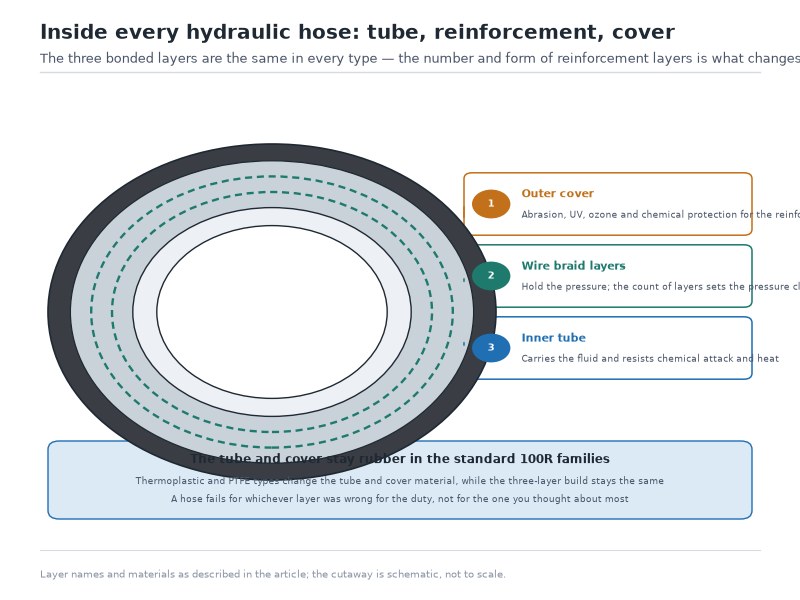
A hydraulic hose temperature rating defines the temperatures at which the three layers of the hose — tube, reinforcement and cover — each stay within their design properties. The tube sets the top end of the fluid rating because it is the layer in direct contact with hot oil. The cover sets the practical limit on external heat, because rubber and thermoplastic covers crack and harden under sustained radiant heat even when the fluid inside is cool. The reinforcement is the layer that turns a temperature problem into a safety problem: once heat breaks the bond between tube and wire, the reinforcement stops sharing the load, and the hose loses working pressure before it shows an obvious leak.
Continuous vs Intermittent Temperature: Which Limit Do You Design To?
Design to the continuous rating, and treat the intermittent figure as an emergency buffer rather than a target. A hose rated -40°C to +100°C continuous with an intermittent figure of +120°C is expected to spend no more than about 10% of its life above +100°C. In real machines, the excursions that push a hose into the intermittent band are the same ones that shorten life: cold-start pressure spikes, a relief valve cracking under stall load, or a hot shutdown after a heavy duty cycle.
Practical test: if the fluid spends most of its working day above the hose’s continuous limit, the hose is mis-specified. Move to a family with a higher continuous rating rather than relying on the intermittent one.
Fluid Temperature vs Ambient Temperature vs Surface Temperature
Three temperatures act on a hose at once, and they are measured in different places:
- Fluid temperature — the oil inside the tube, measured at the return line or reservoir. This is the number the hydraulic hose temperature rating applies to.
- Ambient temperature — the air around the hose. It matters most at the cold end, where it controls flexibility, and in hot enclosures where it prevents the hose from shedding heat.
- Surface temperature — radiant and contact heat on the cover, from exhausts, manifolds, molten metal, or a hot casting. This is the number that is almost never measured and most often responsible for a cover that burns through while the fluid stays cool.
On mobile equipment, fluid temperature typically runs 10°C to 20°C above ambient once the machine is at operating temperature — a planning rule rather than a measured constant for a specific machine — and it climbs further in a stalled or recirculating circuit.
What the Layline and Datasheet Tell You
The printed layline rarely carries a temperature figure, so the temperature rating has to be derived from the standard code printed next to the pressure rating. A hose marked “SAE 100R2AT” or “EN 853 2SN” inherits the temperature limits of that family, which is why reading the layline correctly is the fastest route to the right number.
Hydraulic Hose Temperature Range by Standard Family: The Master Chart
Temperature limits follow the standard family, not the brand. Once you know which family a hose belongs to, its hydraulic hose temperature range is largely fixed, and the differences between families come down to tube compound and construction. Treat the hydraulic hose temperature chart in Table 2 as a starting filter, not an answer, then confirm the individual size against the datasheet.
Table 2. Continuous and intermittent fluid temperature limits by hydraulic hose standard family. Values are typical published limits for oil-based hydraulic fluids; confirm each size against the manufacturer datasheet before ordering. Temperature classes follow SAE J517 for the SAE 100R families and EN 853 / EN 857 / EN 856 for the European equivalents.
| Standard family | Bauwesen | Continuous fluid temp. | Intermittent | Notes |
|---|---|---|---|---|
| SAE 100R1 / EN 853 1SN | Single wire braid, NBR tube | -40°C to +100°C (-40°F to +212°F) | +120°C (+248°F) | Water-based fluids limited to about +70°C |
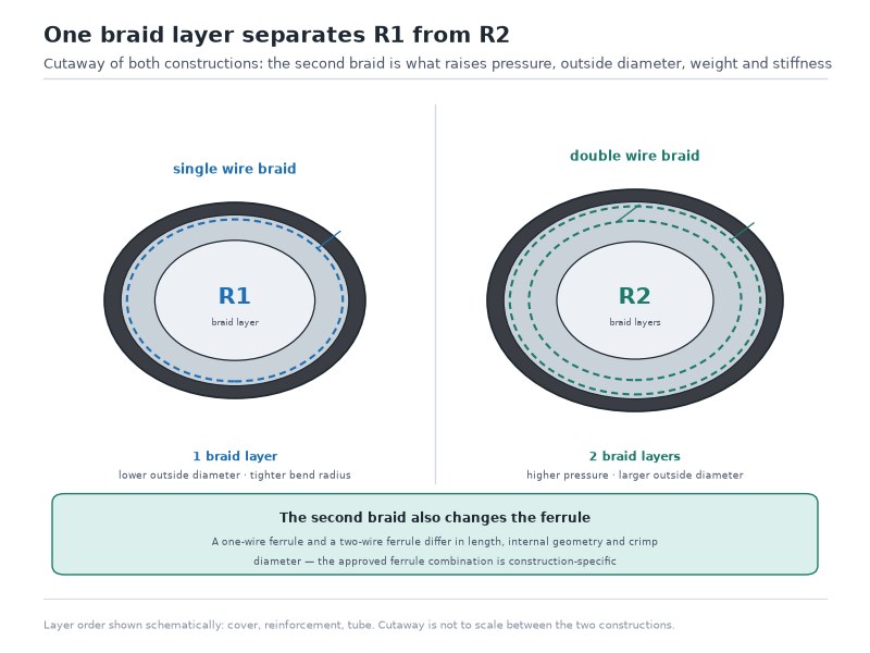
| SAE 100R2 / EN 853 2SN | Double wire braid, NBR tube | -40°C to +100°C (-40°F to +212°F) | +120°C (+248°F) | Same thermal limits as SAE 100R1; higher pressure capability |
| SAE 100R16 / 100R17 / 100R19 | Compact double wire braid | -40°C to +100°C (-40°F to +212°F) | +120°C (+248°F) | Tighter bend radius, same temperature class |
| SAE 100R3 / 100R6, EN 854 1TE / 2TE / 3TE | Textile braid | -40°C to +100°C (-40°F to +212°F) | +120°C (+248°F) | Low pressure; lightest and most flexible |
| SAE 100R4 | Textile braid with wire helix | -40°C to +100°C (-40°F to +212°F) | +120°C (+248°F) | Suction and return duty |
| SAE 100R5 | Textile braid with wire braid | -40°C to +100°C (-40°F to +212°F) | +120°C (+248°F) | Higher-temperature grades of the same family are published to about +135°C continuous |
| SAE 100R7 / 100R8 | Thermoplastic, fibre or wire reinforced | -40°C to +93°C (-40°F to +200°F) | Usually narrower than rubber | Non-conductive; heat is the main limitation |
| EN 856 4SP / 4SH | Four- and six-spiral steel wire | -40°C to +121°C (-40°F to +250°F) | Per manufacturer datasheet | European heavy-duty four- and six-spiral families; same thermal class as SAE 100R12 / 100R13 |
| SAE 100R12 | Four-spiral steel wire | -40°C to +121°C (-40°F to +250°F) | Confirm per datasheet | First step up for hot, high-pressure circuits |
| SAE 100R13 / 100R15 | Six-spiral steel wire | -40°C to +121°C (-40°F to +250°F) | Confirm per datasheet | High heat combined with high pressure |
| SAE 100R14 | PTFE core, stainless steel braid | -54°C to +204°C (-65°F to +400°F) | Higher for short durations | High-temperature PTFE grades are published to about +260°C (+500°F) (per manufacturer data) |
| Dedicated high-temperature rubber hose | Speciality tube compound (for example PKR, a peroxide-cured high-temperature rubber), wire spiral | About -46°C to +150°C (-50°F to +302°F) | Confirm per datasheet | Bridges the gap between standard rubber and PTFE |
| ISO 18752 Type AS / AC / BS / BC | Braid or spiral, classified by temperature and pressure class | -40°C to +100°C (-40°F to +212°F) | Per class | Impulse verified at +100°C; the AS / AC / BS / BC classes are the +100°C group |
| ISO 18752 Type CS / CC / DC | Braid or spiral, elevated-temperature class | -40°C to +120°C (-40°F to +248°F) | Per class | Impulse verified at +120°C; the CS / CC / DC classes are the +120°C group |
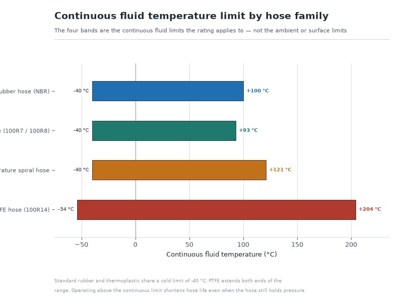
Figure 1. Continuous fluid temperature limits cluster into four bands: standard rubber at -40°C to +100°C, thermoplastic at -40°C to +93°C, elevated-temperature spiral hose at -40°C to +121°C, and PTFE at -54°C to +204°C.
Standard rubber families share one thermal class for the equivalent fluid, and every real increase in temperature capability comes from the tube material rather than the reinforcement: wire construction raises pressure, tube chemistry raises temperature. Thermoplastic hose (SAE 100R7 and 100R8) is a different compound and stops at -40°C to +93°C, while a PTFE core reaches -54°C to +204°C.
Because the class follows the tube compound as well as the reinforcement, the same nominal family name can appear in more than one thermal class depending on how it is built — the naming is set out in the SAE hydraulic hose standards guide, where the J517 families are listed with their construction and rating basis, while how to choose a hydraulic hose covers the same families from the selection side.
If you are sourcing rather than replacing, the temperature class is easier to verify per construction than per catalogue page: braided hydraulic hose covers the standard -40°C to +100°C classes, spiral hydraulic hose covers the +121°C classes, and thermoplastic hydraulic hose covers the non-conductive -40°C to +93°C band.
Rubber, Thermoplastic and PTFE Tube Compounds Compared
Table 3. Tube compounds compared by continuous temperature range, fluid compatibility and first application. Ranges are typical published values — confirm the compound and the limit on the manufacturer datasheet.
| Tube compound | Continuous range | Compatible with | When to specify it |
|---|---|---|---|
| NBR (nitrile) | -40°C to +100°C | Mineral hydraulic oil, petroleum-based fluids | The default for most mobile and industrial circuits |
| CR (chloroprene) | About -40°C to +121°C | Mineral oils, some biodegradable fluids | Moderate heat with standard fluid |
| EPDM | About -40°C to +150°C | Water, steam, brake fluid, phosphate ester | Hot water, steam service, non-petroleum fluids |
| PTFE | -54°C to +204°C, higher grades to +260°C (per manufacturer data) | Most chemicals, aggressive fluids, hot oils | Extreme heat, chemical exposure, broad fluid range |
| Thermoplastic (polyamide) | -40°C to +93°C | Mineral oil, water, air | Light weight, tight bends, non-conductive circuits |
Note the mismatch that catches buyers out: a hose with a heat-resistant EPDM tube is not automatically suitable for mineral oil, and a hose with a standard NBR tube is not suitable for phosphate ester no matter what the temperature rating says. Fluid compatibility and temperature rating have to be satisfied together, which is why a hydraulic hose fluid compatibility chart belongs next to the temperature chart during selection.
Hydraulic Hose Temperature Chart: How Does the Fluid Change the Limit?
Every limit in the family temperature chart — the continuous and intermittent columns for each standard family — assumes mineral hydraulic oil. Change the fluid and the usable temperature window narrows, sometimes dramatically, because the limit is set by whichever fails first — the tube compound, the fluid itself, or the vapour pressure inside the hose.
Table 4. Practical temperature limits by hydraulic fluid type. Where a fluid restricts the limit below the hose’s own rating, the lower figure governs.
| Fluid | Practical continuous limit | Why the limit applies |
|---|---|---|
| Mineral hydraulic oil (HLP, ISO VG 32–68) | Up to +100°C with a standard NBR tube; up to +121°C in a hot-grade family | The tube sets the limit; oil oxidation is reported to accelerate above about +82°C |
| Water-glycol (HFC) | About +70°C (+158°F) | Water loss and steam formation; many standard hose warranties exclude higher temperatures |
| Water-oil emulsion (HFB) | About +70°C (+158°F) | Same mechanism as HFC; confirm with the specific datasheet |
| Phosphate ester (HFD-R) | Set by the substitute tube compound — EPDM to about +150°C, PTFE to +204°C | Standard NBR tube is not compatible; the tube must change, so the rating changes with it |
| Biodegradable ester (HEES, HETG) | Up to +100°C, subject to fluid and tube compatibility testing | Ester fluids attack some elastomers and require a compatible compound |
| Air and inert gas service | About +70°C (+158°F) | Compressed gas removes heat poorly and stores energy; air service carries its own derating |
| Water service (where permitted) | About +85°C (+185°F) | Published catalogue limits for water service are lower than for oil |
Water-based fluid and compressed-air service are the two entries that cause most warranty disputes:
- A water-based fluid lowers the ceiling on a standard rubber hose to roughly +70°C. Scope the fluid first: with HFC or HFB fluid a standard rubber hose is rated to roughly +70°C, so a hose that fails at +95°C on water-based fluid is outside its rated service rather than defective.
- Air service has its own limit and its own pressure derating. A hose chosen on its oil rating and then run on compressed air has to be re-checked against the air-service limit and the air-service pressure derating, not the oil figures.
Does a Higher Temperature Lower the Hydraulic Hose Pressure Rating?
The hydraulic hose pressure rating is measured at a reference temperature under the standard the hose is built to (SAE J517 for the 100R families, EN 853 for 1SN / 2SN), and it does not hold all the way to the top of the temperature range. Above roughly +100°C, the tube softens and the reinforcement bond weakens, so the safe working pressure falls. This is why temperature and pressure must be selected as a pair rather than one after the other.
Table 5. Indicative pressure derating factors for hydraulic hose above +100°C fluid temperature — an industry practice rather than a fixed standard requirement; confirm the factor for the specific family with the manufacturer.
| Fluid temperature | Indicative factor applied to working pressure | What it means in practice |
|---|---|---|
| Up to +100°C (+212°F) | 100% of published working pressure | Full capability; this is the reference condition |
| +100°C to +120°C (+212°F to +248°F) | About 85% to 90% | A 4,000 PSI hose is treated as roughly 3,400 to 3,600 PSI |
| Above +120°C (+248°F) | Manufacturer confirmation required | Move to a family rated for the temperature instead of derating a cooler one |
Always confirm the factor for the specific family with the manufacturer before derating a rating.
The practical consequence: at +115°C a hose rated 4,000 PSI at +100°C is outside its rating at face value, so either derate it and confirm the circuit’s actual peak pressure sits inside the derated figure, or move up to a family whose rating holds at that temperature. Note also that the four-to-one relationship between working pressure and burst pressure is calculated from the rated working pressure, so a derated hose does not carry a proportionally derated burst margin. The full rating hierarchy is set out in our hydraulic hose working pressure vs burst pressure guide.
What Do the Failure Symptoms Look Like at Both Ends?
Failure at the hot end and failure at the cold end look different and are often misdiagnosed as manufacturing faults. Both are selection or application errors, and both are visible before the hose bursts if anyone is looking.
Table 6. Failure mechanisms outside the temperature rating, and the inspection evidence each leaves behind.
| Condition | Mechanism | Visible evidence | Consequence |
|---|---|---|---|
| Sustained heat above the rating | Plasticiser loss and thermal ageing of the rubber | Cover hard, glossy or crazed; surface cracks that do not polish out | Cover cracks, reinforcement corrodes, premature burst |
| Local hot spot on the cover | Radiant or contact heat on an unprotected cover | Localised blisters, charring, or a soft, tacky patch | Cover burn-through and exposed wire |
| Internal overheating of the tube | Tube hardening and loss of adhesion to the reinforcement | Oil seepage through the cover; tube swollen or brittle on section | Delamination, internal leakage, loss of pressure integrity |
| Operation below the cold limit | Rubber passes its glass transition point and loses elasticity | Stiff hose that cracks at the fitting crimp after a cold start | Brittle fracture at the coupling, often on first movement of the day |
| Repeated thermal cycling | Differential expansion between rubber layers and wire | Wrinkled or rippled cover along the hose length | Reduced impulse life and eventual reinforcement fatigue |
A heat-related failure usually ends at the fitting. In our own crimping and testing work, the heat-damaged returns we dismantle most often fracture at the crimp rather than mid-length — an engineering observation from the shop floor, not a measured statistic, and one reason we ask for the fluid and surface temperatures before quoting a hot-duty line. The crimp compresses the tube and the reinforcement against the insert, so any loss of elasticity in the tube shows up first where the layers are under the most mechanical stress, which is why the fitting area dominates the list of common hydraulic hose failure causes.
If you want a visual reference for what a heat-damaged assembly looks like before it fails, the hydraulic hose inspection checklist runs through cover crazing, blistering, wire exposure and fitting-area cracking in sequence.
How Cold Can a Hydraulic Hose Operate?
Cold is the half of the temperature rating that gets ignored until winter. Standard rubber hydraulic hose is rated to -40°C (-40°F), and below that the tube compound stiffens, the bend radius effectively increases, and the fitting crimp becomes the weak point. A hydraulic hose cold weather check is not only about surviving the oil temperature: it confirms that the hose still bends at the lowest ambient temperature the machine will see.
Table 7. Cold-end limits and what changes at each step. Values are typical published limits; low-temperature grades vary by compound and require a cold bend check.
| Grade | Minimum temperature | What changes |
|---|---|---|
| Standard rubber hose (SAE 100R1, 100R2, 4SP, 4SH) | -40°C (-40°F) | Reference condition; flexibility is acceptable to this point |
| Low-temperature / arctic grades | About -55°C (-67°F) for intermittent service (per manufacturer datasheet) | Cold-plasticised compounds and modified wire tension; cold bend verified at -55°C |
| PTFE hose | -54°C (-65°F) | Low-temperature capability comes from the core material |
| Thermoplastic hose | -40°C, and -54°C on some grades (per manufacturer datasheet) | Flexibility is better than rubber at low temperature but heat tolerance is lower |
Two practical points about cold operation:
- Cold reduces effective bend radius compliance. A hose installed at the minimum bend radius in summer may be outside its cold bend limit in January. Route cold-duty hoses with extra slack, and keep the first stretch behind the fitting straight.
- Cold start is the highest-stress moment. Fluid viscosity spikes, pressure peaks before the system warms, and the hose is at its least flexible. If failures cluster in the first minutes of a shift, the cold rating — not the pressure rating — is the number to re-check.
For a fuller treatment of how cold grades and hot grades are sourced differently, including compound selection and cold bend verification, see the companion guide to sourcing hydraulic hoses for extreme temperatures.
How to Select a Hydraulic Hose Temperature Rating: Six Steps
Five inputs fix a temperature rating: the fluid type and its maximum continuous temperature, the maximum excursion and its duration, the ambient range including cold start, the maximum system pressure with surge, and the nearest heat source together with the bore and the bend radius the route allows. Two further items are settled at quote review: the fittings at both ends, and the standard family and certification required. Selection is a sequence, not a single table lookup, and working the six steps in order prevents the two errors behind most temperature-related failures: choosing a hose on its pressure rating alone, and assuming the fluid temperature equals the ambient temperature.
Step 1: Measure the Actual Temperatures, Not the Nominal Ones
Take three readings with the machine at working temperature: fluid temperature at the return line, ambient temperature at the hose’s location, and surface temperature within 100 mm of any hot component. Infra-red measurement of the fitting and cover is enough to expose a hot spot that the fluid temperature never reveals.
Step 2: Pick the Tube Compound for the Fluid
Match the tube to the fluid first, then check the temperature. NBR for mineral oil; EPDM for water-based fluids, steam and phosphate ester; PTFE where the fluid is aggressive or the temperature exceeds what rubber can hold. A high temperature hydraulic hose built on an EPDM tube solves a heat problem but creates a fluid-compatibility question if the circuit runs mineral oil.
Step 3: Choose the Cover for External Heat
The cover determines survival against external heat, abrasion and UV, and it can be upgraded without changing the pressure rating. A heat resistant hydraulic hose is therefore specified on the cover side and a high temperature hydraulic hose on the tube side, and one assembly can carry both properties. Options run from a standard abrasion-resistant rubber cover to heat-resistant compounds, and further to external protection described in Step 5.
Step 4: Re-Check Pressure After Temperature
Take the circuit’s maximum pressure — including the relief valve setting and any measured surge peaks — and compare it against the derated hydraulic hose pressure rating at the actual fluid temperature from Table 5. On a hot circuit, this step often moves the selection up one family even though nothing about the pressure changed.
Step 5: Protect Where the Hose Cannot Be Moved
UV, ozone and abrasion attack the cover from outside, so where a hose runs exposed all season an abrasion-resistant or UV-stable cover is a cover specification rather than a temperature one. Where a hose must pass near a manifold, exhaust or molten metal, a protective sleeve is usually cheaper than upgrading the whole hose. Silicone-coated and glass-fibre sleeves are the standard choice for radiant heat; UHMWPE (ultra-high-molecular-weight polyethylene) sleeves handle abrasion with moderate heat. The hydraulic hose protection sleeve guide covers material choice, temperature limits and cost per foot for each type. Where the route itself forces the bend, check the minimum bend radius before choosing a construction.
Step 6: Verify with Test Data at Temperature
Ask for impulse test evidence at the temperature the hose will see, not just at ambient. Impulse testing is run at elevated temperature precisely because heat is what breaks the tube-to-reinforcement bond, and a hose that passes at ambient can fail at the top of its range.
Selection Checklist: What to Send a Supplier
- Fluid type and its maximum continuous temperature, plus the maximum excursion and duration
- Ambient temperature range at the hose location, including the cold-start figure
- Any radiant or contact heat source within 150 mm of the hose run
- Maximum system pressure, relief valve setting, and measured surge peaks
- Bore size, length, and the minimum bend radius the route allows
- Fittings at both ends and their thread families
- Required standard family (SAE, EN, ISO), certification, and whether a protective or fire sleeve is needed
The five items an enquiry must carry are the fluid type and its maximum continuous temperature, the maximum excursion and its duration, the ambient range including cold start, the maximum system pressure with surge, and the nearest heat source together with the bore and the bend radius the route allows. The fittings and the standard family are confirmed at quote review rather than at enquiry.
Where Does the Heat on a Hydraulic Hose Come From?
Most over-temperature failures are not caused by the hydraulic circuit at all. They are caused by the hose being routed through someone else’s heat source.
Table 8. Common heat sources on mobile and industrial equipment, and the countermeasure that works.
| Heat source | Typical cover exposure | Countermeasure |
|---|---|---|
| Exhaust pipe or muffler | Can exceed the cover limit even at 100 mm distance | Re-route, or fit a reflective or silicone-coated sleeve |
| Engine or transmission housing | Moderate radiant heat, sustained | Stand-off clamps to create an air gap |
| Manifold and hot castings | Very high local surface temperature | Route away; never allow contact |
| Molten metal or slag splash | Instantaneous, destructive | Fire sleeve plus a physical guard |
| Circuit inefficiency (internal leakage, stall, recirculation) | Raises fluid temperature throughout the system | Fix the circuit; the hose is a symptom, not the cause |
| Undersized reservoir or restricted return line | Progressive heat build-up over a shift | Correct sizing; check return-line pressure |
| High ambient (foundry, steel mill, desert) | Reduces the hose’s ability to shed heat | Higher-temperature family plus reflective protection |
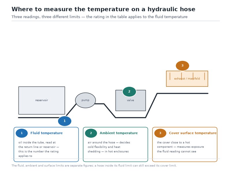
Figure 2. Measuring fluid temperature alone understates the thermal load on a hose. Surface temperature at the cover, near any hot component, is what determines whether protection is needed.
For industrial systems, an operating ceiling of about +85°C (185°F) is common, with oil oxidation reported to accelerate above about +82°C. That ceiling is an industry practice rather than a fixed standard requirement — it protects oil, seals and hoses together, and no single standard fixes it.
What Test Data Should You Ask a Supplier For?
Ask a hot- or cold-duty supplier for five items: impulse test data at your operating temperature, the declared temperature class under the standard the hose is built to, cold bend evidence below -40°C, the cover compound, and a written temperature range on the datasheet. A temperature rating is only as good as the testing behind it. When comparing suppliers for a hot or cold application, ask for these specific items:
- Impulse test results at the elevated temperature the application requires, with the standard named (EN ISO 6803 for impulse testing without flexing; SAE J343 for the SAE 100R test procedures) and the cycle count achieved at 133% of working pressure.
- The declared temperature class of the hose under the standard it is built to, for example ISO 18752 Type CS, CC or DC for the +120°C classes, rather than a marketing temperature claim.
- Cold bend test evidence at the low end, if the application operates below -40°C.
- Cover compound identification, since cover heat resistance and tube heat resistance are separate properties.
- A written temperature range on the datasheet or certificate, not only on the website.
> Temperature enquiry — fluid ___ at ___°C continuous, ___°C peak for ___ minutes; ambient ___°C to ___°C (cold start ___°C); nearest heat source ___ mm from the hose run; maximum system pressure ___ PSI (relief ___ PSI, surge ___ PSI); bore ___ with the bend radius the route allows ___ mm. For quote review: fitting and standard family required ___. Please confirm the temperature class, the derated working pressure at that fluid temperature, and the impulse evidence at that temperature.
Those five questions are also the five documents we send with a hot- or cold-duty quote: the impulse result at your operating temperature, the declared temperature class under the standard we build to, the cold bend evidence if the machine starts below -40°C, the cover compound identification, and the written temperature range on the datasheet. Send the fluid type with the measured fluid and surface temperatures and our engineers will answer all five for your duty. Request a quote and free samples.
This is the point where a high temperature hydraulic hose separates itself from a standard hose with a heat-resistant label. The reinforcement, the tube compound and the adhesion system all have to be matched to the temperature class, and only test data at temperature proves they were.
What an Over-Temperature Event Does to the Rest of the Circuit
An over-temperature event is rarely confined to the hose that failed. A single severe excursion raises the fluid temperature throughout the circuit, and the same heat that hardens the tube of one assembly ages every seal, hose and accumulator bladder it reaches. With the system ceiling commonly held near +85°C and oil oxidation reported to accelerate above about +82°C, a hose failure that follows a hot run is the visible symptom of a circuit-level event.
Treat it that way in the repair: replace the failed assembly, then check the hoses and seals on the same circuit, and find out why the fluid ran hot — internal leakage, a stalled function, a restricted return line, or a reservoir too small for the duty.
How to Read a Manufacturer’s Temperature Derating Table
A derating table published by another manufacturer answers one question: how much working pressure does this family still carry at the temperature you measured? Read the top row first, because that is the reference condition — usually 100% of published working pressure at or below +100°C. The next rows give an indicative factor, typically about 85% to 90% between +100°C and +120°C, and the line above +120°C usually reads manufacturer confirmation required rather than a number.
Two habits keep that reading safe. Take the factor as a starting point and confirm it for the specific family with the supplier, because the factors are an industry practice rather than a fixed standard requirement. And remember that the factor applies to the working pressure, which is the base for the minimum burst figure, so a derated hose does not carry a proportionally derated burst margin.
Heat Sleeve or Higher-Temperature Hose? Choosing the Cheaper Fix
Two different problems are solved in two different places, and mixing them up is expensive. External heat acting on the cover — an exhaust, a manifold, molten metal splash — is a cover-side problem: fix it with routing, a stand-off clamp or a protective sleeve. Heat carried in the fluid is a tube-side problem: the tube compound has to change, and with it the standard family and the temperature class.
The decision rule follows directly. If the fluid temperature is inside the family’s continuous limit and the cover is the part being cooked, a sleeve is usually the cheaper fix and it leaves the pressure rating untouched. If the fluid itself is running above the family’s continuous limit, no sleeve helps: the sleeve protects the outside of the hose, and the heat is already inside the tube.
Which Hydraulic Hose Temperature Range Suits Each Application?
Industry temperature bands are a comparison aid. Select the hose against the temperatures actually measured on the machine.
Table 9. Fluid temperature band and class specified by application — mobile and off-road duty. Values are planning bands, not measured data for a specific machine.
| Application | Typical fluid temperature | External exposure | Class normally specified |
|---|---|---|---|
| Mobile construction (excavator, loader, dozer) | +70°C to +95°C | Engine-bay radiant heat, abrasion | SAE 100R2 / 100R16; spiral where pressure demands it |
| Underground mining equipment | +80°C to +100°C | High ambient, heavy abrasion, fire risk | 4SP / 4SH with abrasion-resistant or UHMWPE cover |
| Agricultural and utility equipment | +60°C to +90°C | Moderate, UV | SAE 100R2, 100R16 |
| Cold storage and refrigerated logistics | +20°C to +50°C | -25°C to -40°C ambient | Standard or low-temperature rubber family |
| Arctic and winter construction | +40°C to +70°C | -40°C to -55°C ambient | Low-temperature grades, cold bend verified |
Table 10. Fluid temperature band and class specified by application — industrial and process duty. Values are planning bands, not measured data for a specific machine.
| Application | Typical fluid temperature | External exposure | Class normally specified |
|---|---|---|---|
| Steel mill and foundry | +60°C to +90°C | Extreme radiant heat, splash | SAE 100R12 / 100R13 plus fire sleeve |
| Hydraulic presses and machine tools | +50°C to +80°C | Low | Standard rubber family, derated for pressure |
| Offshore and marine deck machinery | +60°C to +90°C | UV, salt spray, enclosure heat | SAE 100R13 / 100R15 with marine-grade cover |
| Die casting and injection moulding | +45°C to +70°C | Very high radiant heat | SAE 100R12 plus protective sleeve |
| Test benches and dynamometers | +70°C to +110°C | High, sustained | SAE 100R12 / 100R13 or PTFE |
| Chemical and petrochemical processing | Fluid-dependent, up to +200°C | Process heat | PTFE with stainless steel braid |
A high temperature hydraulic hose is specified for the fluid side, while a heat resistant hydraulic hose specification is usually about the cover and the external environment, and that distinction decides most sourcing questions. A machine can need both, and they are solved differently.
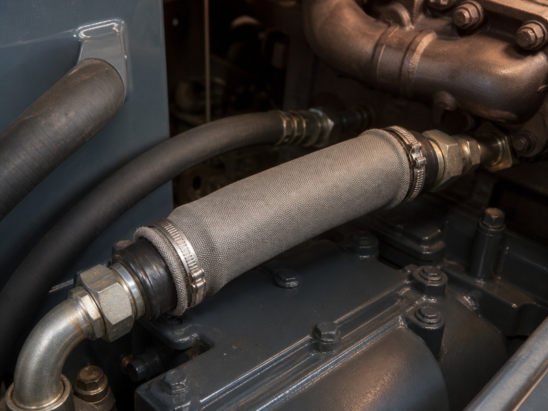
Figure 3. Where a hose cannot be re-routed away from a hot component, a silicone-coated or glass-fibre protective sleeve is the practical fix — it addresses cover temperature without changing the hose’s fluid-side rating.
Frequently Asked Questions
What is the temperature rating of a hydraulic hose?
For standard rubber hydraulic hose, the continuous hydraulic hose temperature rating is -40°C to +100°C (-40°F to +212°F), with an intermittent allowance of +120°C (+248°F). Elevated-temperature spiral families are rated to +121°C, thermoplastic hose to +93°C (-40°F to +200°F), and PTFE hose from -54°C to +204°C (-65°F to +400°F).
What is the maximum temperature for a hydraulic hose?
The maximum continuous fluid temperature is +100°C for standard rubber families and +121°C for the SAE 100R12, 100R13 and 100R15 spiral hose. PTFE hose extends the ceiling to +204°C (-65°F to +400°F), and high-temperature PTFE grades are published to +260°C (+500°F) (per manufacturer data). These figures apply to mineral oil; water-based fluids reduce the practical limit to about +70°C, and the hydraulic hose temperature chart in Table 2 shows where each family sits.
How do I read a hydraulic hose temperature rating on the layline?
The layline normally shows size, the standard family and the working pressure, not a temperature. Identify the family code — for example SAE 100R2, EN 853 2SN, EN 856 4SH or SAE 100R14 — and read the temperature limit from the standard’s published table. If the marking is worn or the family is unknown, replace the hose rather than assuming the rating.
What is the temperature rating of a high pressure hydraulic hose?
Pressure and temperature are selected as a pair, so a high pressure hydraulic hose does not carry a single temperature figure. Above the family’s continuous limit the published working pressure has to be derated, which means a 4,000 PSI line that runs hot is no longer a 4,000 PSI line for selection purposes. State the maximum pressure and the maximum temperature together on the enquiry, because the derated pressure at temperature is what the supplier has to design and test to.
How do I protect a hydraulic hose from sun and UV?
UV, ozone and heat all attack the cover from outside, and cover damage is what exposes the reinforcement to corrosion. For hose that runs exposed all season, specify a UV-stable or abrasion-resistant cover and check the routing so the cover is not resting on hot structure; where the run is fixed, a protective sleeve adds UV and abrasion resistance without touching the fluid-side rating. Cover properties are specified separately from the tube, so ask for the cover compound by name rather than relying on the general temperature rating.
How long does a hydraulic hose last at high temperature?
There is no fixed service life for a hot circuit, and no defensible single number to quote: life depends on the fluid temperature, the excursion count, the cover exposure and the pressure duty together. What can be managed is the inspection interval — a hose in sustained hot service is checked more often than a cool-duty line, and any hose that has seen a severe over-temperature event is a candidate for proactive replacement. Our guide on how to choose a hydraulic hose sets out the same condition-based logic for service intervals.
What temperature can a hydraulic hose be steam-serviced at?
Steam service is a tube-compound question rather than a hose-rating question. A standard NBR tube is built for oil, so steam duty calls for an EPDM tube with a compatible cover and, at the top of the range, a PTFE core with stainless steel braid. Because steam combines high temperature with a non-oil fluid, confirm both the compound and the pressure derating with the manufacturer before specifying, and keep the assembly’s own documentation with the machine.
What is the coldest temperature a hydraulic hose can operate at?
Standard rubber hydraulic hose is rated to -40°C (-40°F). Low-temperature and arctic grades extend this to -55°C (-67°F) (per manufacturer datasheet), with cold bend performance verified at that temperature, and PTFE hose reaches -54°C (-65°F). Below the rated minimum the hose stiffens and failures appear at the fitting crimp after cold starts.
Why do suppliers publish different temperature limits for the same hose family?
Three things move the published number: whether it is a continuous or an intermittent limit, whether the figure assumes mineral oil or a water-based fluid, and whether the standard class is quoted at the reference condition or at an elevated test temperature. Some catalogues also round between °C and °F. When two datasheets disagree, compare the basis before the number — same fluid, same fluid-side or cover-side limit, same test standard — and ask the supplier which basis the figure is quoted on.
How do I write the temperature requirement into an enquiry?
Give the supplier five items so the temperature class can be fixed without assumptions: the fluid type and its maximum continuous temperature, the maximum excursion and its duration, the ambient range at the hose location including the cold-start figure, the maximum system pressure with the relief-valve setting, and the distance to the nearest radiant or contact heat source. With those five the supplier can confirm the family, the class and the derating in one pass, instead of quoting a catalogue hose and leaving the temperature decision to the fitter.
Does the temperature rating change with hose size?
The temperature limit does not change with bore size, but the practical margin does. Large-bore hose has more rubber mass and dissipates heat differently, and pressure ratings fall as bore rises, so a large-bore hose at high temperature is often working closer to both limits at once.
How often should hydraulic hose be replaced in hot applications?
There is no fixed interval. Replace on condition, using inspection findings, and treat any hose that has seen a significant over-temperature event as a candidate for proactive replacement regardless of age — a single severe excursion can damage every hose and seal in the circuit, not just the one nearest the heat.
Final Verdict: Match the Class to the Measured Temperature, Then Verify It
Getting the hydraulic hose temperature rating right comes down to three decisions: measure the real temperatures rather than the nominal ones, choose the tube compound for the fluid and the cover for the environment, then re-check the pressure rating against the temperature you measured. Standard rubber families at -40°C to +100°C cover the majority of mobile and industrial circuits. Above +100°C, step up to the +121°C spiral classes; above +150°C, or where the fluid is aggressive, move to PTFE. Below -40°C, specify a low-temperature grade rather than hoping a standard hose will stay flexible.
About HENGHUA
HENGHUA manufactures hydraulic hose and assembled hydraulic lines across the families this guide covers — wire braided, wire spiral, textile reinforced and thermoplastic — together with the fittings and adapters that complete the assembly: JIC, ORFS, NPT, BSP, metric, SAE flange, banjo, ferrules, reusable and one-piece fittings. Because the tube compounds are mixed, the wire reinforcement braided or spiralled, the cover extruded and the assemblies crimped and tested in-house, the temperature class of a hose can be confirmed with test data rather than a catalogue claim. Impulse and hydrostatic testing is carried out on in-house equipment, and certification documentation — including ISO 9001, CE, MSHA (Mine Safety and Health Administration), CCS (China Classification Society), ABS (American Bureau of Shipping), DNV and API marks relevant to specific product lines — is issued with the shipment where the application requires it.
That in-house control is what allows a temperature-specific answer rather than a generic one: if your circuit runs hot, runs cold, or runs both across a season, send us the fluid type, the measured fluid and surface temperatures, the pressure and the fittings at both ends, and our engineers will confirm the correct family and temperature class for the duty. Factory-direct supply also means short lead times on bulk orders and free samples for qualification testing. Ask for a quote with test data.
 English
  Spanish
  Portuguese
  French
  German
  Arabic
  Russian