
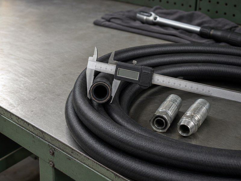
Hydraulic hose sizing converts a required flow rate into a bore diameter the system can live with. Size a line too small and the oil moves too fast: pressure drop rises, the oil heats, and the hose, its fittings, and the pump all age faster. Size it too large and you pay for weight, extra fluid volume, wider bend radii, and slower response.
The method is short: calculate the flow velocity in the line, compare it with the velocity band allowed for that duty, and choose the smallest standard dash size that keeps the line inside the band. For the most common case — a -12 (3/4 inch, DN19) pressure line carrying 20 GPM — that gives 14.5 ft/s (4.4 m/s), inside the 15–20 ft/s band.
This guide gives the formula and a velocity chart, the flow capacity table most engineers keep on the wall, why a sizing calculator and a nomogram both need a pressure-drop check, how much pressure drop and heat an undersized line really adds, a complete worked example, a printable one-page hydraulic hose size chart PDF for the workshop wall, and the commercial side: cost, minimum order quantity, and lead time.
What Does “Hose Size” Actually Mean on a Hydraulic Line?
Only one dimension matters for flow: the nominal inside diameter (ID). Everything else about hose size is a label or a consequence.
- Strichstärke is the nominal ID in sixteenths of an inch, the sizing convention defined in SAE J517 and used across the fluid power industry, so a -8 hose has a nominal bore of 8/16 in, or 1/2 in.
- DN is the metric label for the same nominal bore, quoted in millimetres, so -8 corresponds to DN12, -12 to DN19, and -16 to DN25. DN is a rounded nominal series rather than a measured bore: the -20 size is written DN 31 (1-1/4 in, or 31.5 to 31.8 mm depending on which standard table you read), and some catalogues print the same size as DN 32 — all three labels describe one nominal bore.
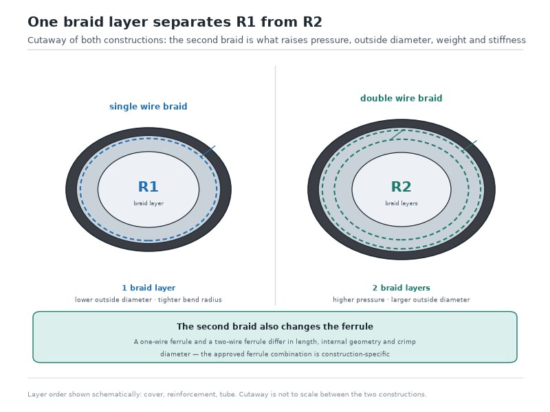
- Outside diameter (OD) is not a size you select. It follows from the construction — how many wire layers of what type, plus the cover — so a 4-spiral hose of a given dash is noticeably larger and stiffer in the OD than a 2-wire braid of the same dash.
- The real ID carries a tolerance. Nominal is not exact, and the actual bore of two constructions under the same dash number can differ by fractions of a millimetre in either direction.
Dash size and DN labels for the sizes used in this guide (the complete -2 to -48 sequence is in the size chart guide)
| Strichstärke | Nominal ID (in) | DN label |
|---|---|---|
| -4 | 0.25 | DN6 |
| -6 | 0.375 | DN10 |
| -8 | 0.5 | DN12 |
| -10 | 0.625 | DN16 |
| -12 | 0.75 | DN19 |
| -16 | 1.0 | DN25 |
| -20 | 1.25 | DN 31 |
| -24 | 1.5 | DN38 |
| -32 | 2.0 | DN51 |
Read the bore and the pressure class off the marking line on the hose cover before you assume anything about a line that is already on the machine; how to interpret those markings is set out in our hydraulic hose layline guide. The dash, inch, millimetre, DN and flow conversion for every size — including the bores this calculation never touches — sits in our complete hydraulic hose size chart.
Why Is Hydraulic Hose Sizing a Flow Calculation Rather Than a Catalogue Choice?
Bore is set by velocity, not by the fittings you happen to have in stock or by whatever bore the original machine used. Three limits decide how small a line can be, and they all point the same way.
- Velocity ceiling. Every line duty has a velocity band that keeps flow in a range where pressure loss and wear stay acceptable. Exceed the top of the band and the penalties compound.
- Allowable pressure drop. A line that is too small converts pressure into heat along its length. The longer the run, the more of your working pressure disappears before it reaches the actuator.
- Physical envelope. Bend radius, OD clearance, weight, and the fluid volume the line adds to the circuit. These limit how large you can practically go, and they are the reason oversizing is not free either.
Before any calculation, five inputs have to be fixed. Missing any one of them is why sizing arguments happen after the machine is built.
- Maximum flow in L/min or GPM — the sum of every function that can run at the same time, not just the largest one.
- Line duty — pump suction, return, or pressure line, and if pressure, the working pressure range.
- Pressure and surge — the highest pressure the line sees, including relief setting and pressure spikes.
- Fluid and temperature range — mineral oil at 40 °C behaves differently from cold oil at start-up, and water-glycol or phosphate-ester fluids change the tube choice.
- Run length and routing — long runs and multiple bends carry pressure drop that a short bench line does not.
Note that bore and pressure class are two separate decisions. A hose can be the right size and the wrong pressure rating, and the reverse is equally possible. The wall of wire that carries 5,000 psi has no bearing on how fast the oil travels through the tube.
How Do You Calculate the Right Hose Size From Flow Rate?
A hose sizing calculation needs only two inputs: the maximum hydraulic hose flow rate the line must carry, and the bore you are testing. Velocity is flow divided by the internal area of that bore, which gives two forms of the same relation.
What is the hydraulic hose velocity formula?
- Inch units: velocity (ft/s) = 0.408 × flow (GPM) ÷ ID² (in)
- Metric units: velocity (m/s) = 21.22 × flow (L/min) ÷ ID² (mm)
Written as symbols, the two forms used on this page are v (ft/s) = 0.408 × Q (gpm) ÷ d² (in) and v (m/s) = 21.22 × Q (l/min) ÷ d² (mm), where v is the mean fluid velocity, Q is the volumetric flow rate and d is the internal diameter of the bore. The exact inch constant is 0.4085, so a velocity rounded with 0.408 reads marginally low. The three constants used across these guides — 0.408 here, 2.448 in the rearranged form used by our hydraulic hose size chart guide, and 3.117 in the area form — are three writings of one relation that differ by less than 0.2 percent, purely because of how the units are converted; the difference changes no dash size choice.
The squared term is what makes sizing decisions so sensitive. Doubling the bore cuts the velocity by roughly four times at the same flow, and a single step down in dash size raises it by about 25 to 30 percent.
A -8 hose (0.50 in) carrying 20 GPM illustrates the point: 0.408 × 20 ÷ 0.25 gives 32.6 ft/s, or about 9.9 m/s. That is far above any sensible pressure-line band. Moving to -12 raises the area by 2.25 times and drops the velocity to 14.5 ft/s (4.4 m/s), which sits comfortably inside the medium-pressure band (Figure 1).
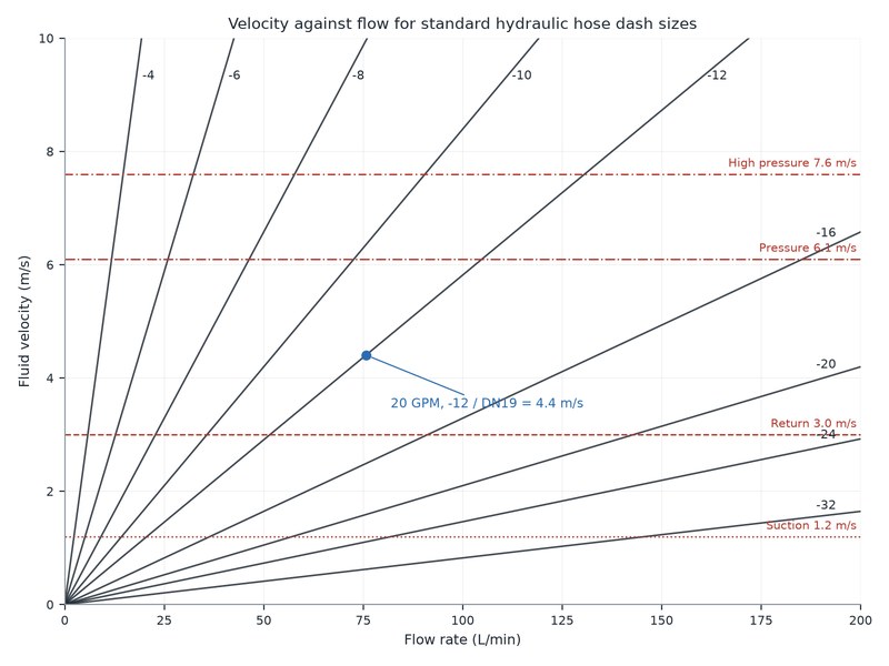
Figure 1. Velocity against flow for the standard dash sizes. The steep curves on the left show why small bores reach the velocity limit after only a few litres per minute.
How do you calculate the minimum hose ID in three steps?
- Find the minimum bore from the velocity band. Minimum bore (in) = √(0.408 × GPM ÷ v), where v is the top of the velocity band for that line duty — 4 ft/s for a suction line, 10–15 ft/s for a return line, and 20 ft/s for a pressure line. In metric units, minimum bore (mm) = √(21.22 × L/min ÷ v).
- Round up to the next standard dash size. The next larger bore is the design value: the bands already contain the engineering margin, and the next size down sits above the velocity limit for that duty.
- Re-check pressure drop and the physical envelope. Calculate or read the pressure loss per unit length for the run, add the losses from fittings and bends, and confirm that the OD, bend radius, and assembly weight still fit the machine.
If a line feeds several actuators at once, size it on the sum of those flows at the moment they overlap, and check whether any single function at full stroke changes the picture. A pressure line sized for one function and later asked to carry two is one of the most common sources of unexplained overheating on mobile equipment.
What Flow Velocity Should You Allow in Suction, Return, and Pressure Lines?
A suction line runs at 2–4 ft/s, a return line at 10–15 ft/s, a medium-pressure line at 15–20 ft/s and a high-pressure line at 20–25 ft/s; the bands differ because the penalties differ, and these are the line-sizing values used in fluid power practice in both unit systems. They differ because the consequences of high velocity differ: on a pressure line the cost is heat and lost pressure, on a suction line it is cavitation at the pump inlet, which damages the pump rather than the hose.
Velocity bands used in fluid power line-sizing practice, by line duty
| Line duty | Velocity band (ft/s) | Velocity band (m/s) | What happens above the band |
|---|---|---|---|
| Pump suction | 2–4 | 0.6–1.2 | Pressure at the pump inlet falls, oil flashes, cavitation erodes the pump and the noise rises |
| Return line | 10–15 | 3.0–4.6 | Heat builds in the tank line, back pressure loads the return side, oil oxidises faster |
| Medium pressure (500–2,000 psi) | 15–20 | 4.6–6.1 | Pressure drop and heat rise sharply; the circuit loses usable pressure at the actuator |
| High pressure (2,100–5,000 psi) | 20–25 | 6.1–7.6 | Erosion of the tube, pressure spikes, and short hose and fitting life |
The upper end of each band is for intermittent or occasional flow. On a line that runs continuously at full flow, size to the lower half of the band, because the loss is continuous too. Sizing to the lower half of the band for continuous duty is a line-sizing practice rather than a fixed standard requirement (Figure 2).
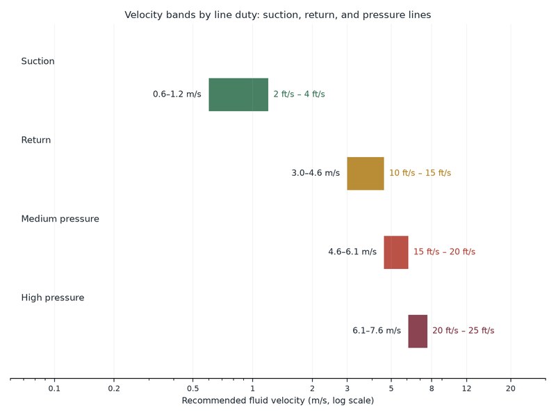
Figure 2. The three velocity bands side by side. Suction lines sit an order of magnitude below pressure lines, which is why a suction line is always the largest bore on the machine.
These bands describe steady turbulent flow in a clean line at working temperature; cold oil at start-up, a blocked suction strainer or a fluid far outside its viscosity range sit outside them. A suction line is sized by velocity and confirmed by inlet vacuum: a line inside the 2–4 ft/s band can still cavitate if the strainer is clogged or the inlet sits too high above the oil level, so confirm the size on the machine before you order. If you would rather have the bore confirmed from your own duty data, send the flow rate and the line duty.
Hydraulic Hose Size vs GPM: How Do You Size a Line Without a Chart?
Maximum flow is the velocity relation rearranged: Q (GPM) = v (ft/s) × ID² (in) ÷ 0.408, and Q (L/min) = v (m/s) × ID² (mm) ÷ 21.22. The reverse form here is evaluated at the exact constant, so a flow computed with 0.408 reads about 0.1 percent high. Choose the velocity from the band for the line duty — 4 ft/s for suction, 10 ft/s for a continuously running return line, and 15 to 20 ft/s for a pressure line — and the formula returns the flow that bore carries. The full dash-by-dash flow column, every size from -4 to -32 at each band, is in our complete hydraulic hose size chart.
Three worked values fix the scale, each computed from the formula above: a -8 (0.50 in) suction line at 4 ft/s carries 2.4 GPM (9.3 L/min); a -12 (0.75 in) return line at 10 ft/s carries 13.8 GPM (52.1 L/min); and a -16 (1.00 in) pressure line at 20 ft/s carries 49.0 GPM (185.4 L/min). Where the duty falls between two bores, the larger bore is the answer, because the bands already contain the margin that a start-up, a cold morning, or a partially blocked strainer will consume.
How Do You Read a Hose Sizing Nomogram?
A hose sizing nomogram — often spelled nomograph — is a three-scale chart that solves the velocity formula graphically. Inside diameter sits on the left scale, flow in the middle, and velocity on the right, all with logarithmic spacing. Joining any two known values with a straight edge gives you the third where the line meets the remaining scale.
How do you read the three scales on a nomogram?
- Mark the flow. Find the required flow on the flow scale, in GPM or L/min depending on the version of the chart.
- Mark the target velocity. Find the band for the duty on the velocity scale — the top of the suction, return, or pressure band — the top of the suction, return, or pressure band.
- Draw the line. Join the two marks with a straight edge and extend it to the inside diameter scale on the left, where the bore is read.
- Read to the next larger ID. If the line crosses between two bores, select the larger one. The scales return the smallest acceptable bore, and every step below it raises velocity above the band.
The attraction of the nomogram is speed: it replaces a calculation with a ruler, and it shows the whole family of bores at once, so you can see immediately how much flow a step up or down would buy (Figure 3).
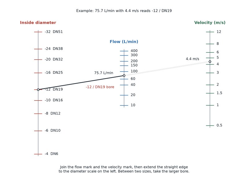
Figure 3. A three-scale nomogram: join the flow mark and the velocity mark, then extend the straight edge to the diameter scale on the left.
What can a hose sizing nomogram not tell you?
A hose sizing nomogram answers one question: what bore holds velocity inside the band at this flow. It does not know your fluid, your run length, or your duty cycle. Before you accept its answer, check the following:
- Viscosity and temperature. Charts are normally plotted for a mineral oil near ISO VG 46 at working temperature. Cold oil at start-up raises pressure loss in every line, and the nomogram has no scale for it.
- Run length. A long line needs a pressure-drop check as well as a velocity check, which is the subject of the next section.
- Fittings and bends. Each elbow, adapter, and coupling adds loss that the bore alone does not describe.
- Duty cycle. Continuous full-flow duty justifies the lower half of the band; intermittent duty can use the upper half.
Used in that order, the nomogram is a fast first pass and a useful cross-check on the calculation. Used alone, it is the reason some machines arrive with a pressure line that is technically inside the band and still runs hot.
Is There a Hydraulic Hose Sizing Calculator That Gives the Right Dash Size?
A hydraulic hose sizing calculator performs the arithmetic of this guide from the hydraulic hose flow rate you enter, and a sound one returns the smallest standard bore that holds velocity inside the band you select. Three inputs decide whether its answer survives on the machine, and none of them sits on the calculator’s screen.
- Start-up temperature. Calculators are set up for mineral oil at working temperature, near ISO VG 46. Cold oil on a January start raises pressure loss in every line, so a suction line that passes at 40 °C can still starve the pump at 0 °C.
- Real run length. Bore sets velocity; length, fittings and bends set the hydraulic hose pressure drop along the run. A calculator that ignores run length can approve a bore that loses several bar before the oil reaches the actuator.
- Duty cycle. Continuous full-flow duty is sized on the lower half of the band, intermittent duty on the upper half.
Use the calculator for the first pass, then confirm those three points and check the resulting dash size against its published pressure rating and bend radius before ordering.
How Does Hydraulic Hose Sizing Affect Pressure Drop and Heat?
Flow through a hose loses pressure to friction, and the amount lost rises much faster than the flow itself. In the low-velocity range, where the flow is laminar, doubling velocity roughly doubles the loss per unit length. In the turbulent range that most hydraulic lines actually work in, doubling velocity roughly quadruples the loss, because the loss tracks velocity raised to a power close to two.
That behaviour sets the design rule: keep the total loss in the pressure line at maximum flow to a small fraction of the system pressure, commonly a few percent, and check it on any run longer than a few metres. The few-percent target is itself a line-sizing practice rather than a fixed standard requirement. On short bench assemblies the loss is negligible; on a 10 m pressure line in a machine, it can be the difference between an actuator that performs and one that is sluggish.
How much heat does a 20 bar pressure loss generate?
Every bar of pressure lost appears as heat in the oil. The relation is short:
Heat (kW) = pressure loss (bar) × flow (L/min) ÷ 600
The numbers add up quickly. A 20 bar loss in a return line carrying 76 L/min puts about 2.5 kW into the oil — roughly the output of a small immersion heater running continuously inside the tank, with the hydraulic hose itself as the heating element.
Heat generated by pressure loss at three common flows
| Pressure loss | 40 L/min (10.6 GPM) | 76 L/min (20 GPM) | 120 L/min (31.7 GPM) |
|---|---|---|---|
| 5 bar (73 psi) | 0.33 kW | 0.63 kW | 1.00 kW |
| 10 bar (145 psi) | 0.67 kW | 1.27 kW | 2.00 kW |
| 20 bar (290 psi) | 1.33 kW | 2.53 kW | 4.00 kW |
| 30 bar (435 psi) | 2.00 kW | 3.80 kW | 6.00 kW |
The practical consequence is that an undersized line rarely announces itself as a failure. It shows up as a machine that runs hot, oil that darkens early, seals that harden and weep, and a pump that is louder than it should be — all traced back eventually to a hose that is one dash size too small. Because a hydraulic hose pressure drop of this kind is spread along the line rather than concentrated at a component, it is easy to blame the cooler, the relief valve, or the oil instead.
The limits of the method deserve stating. Calculated and chart-based loss figures assume the rated viscosity, a clean fluid, and fully open passages. They do not cover a kinked hose, a collapsed liner, an internally delaminated suction line, or a mismatch at a fitting that narrows the flow path to less than the hose bore. If the measured hydraulic hose pressure drop is far above the calculated figure, stop sizing and inspect the assembly before ordering a larger line.
Worked Example: Hydraulic Hose Sizing on a 20 GPM System
The three lines in this example land on -12 for the pressure line, -12 for the return line (-16 on continuous duty) and -24 for the suction line; the arithmetic behind each answer is worked through below.
A mobile system with a single pump delivering 20 GPM (75.7 L/min) at 2,000 psi needs a pressure line, a return line, and a suction line. All three are sized from the same hydraulic hose flow rate figure. Runs are short, the fluid is mineral oil, and the machine works a normal duty cycle.
Sizing the three lines of a 20 GPM system from the velocity bands
| Line | Velocity band used | Minimum ID required | Selected size | Actual velocity at 20 GPM | Verdict |
|---|---|---|---|---|---|
| Pressure line | 20 ft/s (6.1 m/s) | 0.639 in (16.2 mm) | -12 / DN19 (0.75 in) | 14.5 ft/s (4.4 m/s) | Inside the band with margin for surge |
| Return line | 15 ft/s (4.6 m/s) | 0.738 in (18.7 mm) | -12 / DN19 (0.75 in) | 14.5 ft/s (4.4 m/s) | At the top of the band; -16 if the line runs continuously |
| Suction line | 4 ft/s (1.2 m/s) | 1.428 in (36.3 mm) | -24 / DN38 (1.5 in) | 3.6 ft/s (1.1 m/s) | Inside the band; -20 would run at 5.2 ft/s (1.6 m/s) |
Three observations follow from the table. The pressure line and the return line land on the same dash size at this flow, which is why -12 becomes the default pressure line in the 15 to 25 GPM class. The return line sits at the top of its band and would move to -16 on a machine that runs continuously at full flow. The suction line is two dash sizes larger than the pressure line, which is normal and is the reason suction hose is stocked in the bigger bores.
What changes when the flow doubles?
Run the same three lines at 40 GPM (151 L/min) and the picture changes:
The three lines of the 20 GPM system re-run at 40 GPM (151 L/min): every line moves up about two dash sizes, not a factor of two in bore
| Line | Selected size | Velocity at 40 GPM | Note |
|---|---|---|---|
| Pressure line | -16 / DN25 (1.0 in) | 16.3 ft/s (5.0 m/s) | -12 would run at 29 ft/s (8.8 m/s), well over the band |
| Return line | -20 / DN 31 (1.25 in) | 10.4 ft/s (3.2 m/s) | Keeps the tank line inside the lower half of the return band |
| Suction line | -32 / DN51 (2.0 in) | 4.1 ft/s (1.2 m/s) | At the suction limit; check the strainer and inlet height as well |
Two things are worth noticing. Doubling flow moves every line up by roughly two dash sizes, not by a factor of two in bore, because velocity scales with the square of the diameter. And the higher you go in bore, the more the fittings, ports, and bend radii matter, because a -32 hose will not bend where a -12 hose did.
When Is a Larger Hose the Wrong Answer?
Oversizing is a real error, just a quieter one. The cost appears as money, weight, space, and system behaviour rather than as heat, and hydraulic hose velocity below the band is not a fault in itself.
Undersized, right-sized, and oversized hydraulic hose compared
| Criterion | Undersized | Right-sized | Oversized |
|---|---|---|---|
| Velocity | Above the band | Inside the band | Below the band |
| Pressure drop and heat | High and continuous | Acceptable by design | Low |
| Bend radius and routing | Easier to route, tighter bends possible | As published for the size | Demands more space; can force a longer assembly |
| Fluid volume in the circuit | Lowest | Moderate | Highest; adds oil, weight, and slightly slower response |
| Assembly weight and support | Lightest | Normal for the duty | Heavier; needs more clamping and support |
| Cost | Lower component cost, higher running cost | Lowest total cost over life | Higher component cost per metre and per fitting |
| Service life of hose and fittings | Reduced by heat, erosion, and pressure spikes | As designed | Long on the line, unchanged elsewhere |
The engineering judgement in the middle column is the point: “right-sized” means inside the band for the duty cycle, not at the smallest bore that survives. Two refinements to the rule are worth keeping.
- On a suction line, erring large is the safer error. Extra bore in a suction line costs money and space, and it buys margin against a cold start, a partially blocked strainer, and a pump that draws more than expected. Cavitation damage to the pump is far more expensive than the next dash size up.
- On a pressure line, a larger bore adds fluid volume to the circuit. That volume is pressurised and depressurised on every cycle, which slows response on servo and closed-loop systems and can make a shock problem worse rather than better.
One further caution belongs here. A machine that overheats has several possible causes, and the hose is one of them. Check the relief valve setting, the pump condition, the return filter and the cooler capacity as well: a larger bore corrects the line-loss share of the heat and leaves the other sources in place.
How Does Cold Start-Up Change the Hose Size You Need?
Cold oil is the case the velocity bands do not describe, and it is the case a machine meets every winter morning. The bands assume mineral oil at working temperature, near ISO VG 46; at start-up the viscosity can be several times higher, so pressure loss rises along every line at the same flow.
The consequence is unequal. On a pressure line the extra loss costs a little usable pressure until the oil warms, while on a suction line it can pull the inlet below atmospheric and start cavitation before the oil reaches temperature. Two working responses follow. Size the suction line on the lower half of its band, or one dash size above what the velocity calculation asks for, so that cold-oil viscosity has somewhere to go. And confirm the result on the machine with an inlet vacuum gauge, because a suction line that sits inside its band at 40 °C can still be short of margin at 0 °C.
Return Line Sizing: When Does -12 Become -16?
At 20 GPM a -12 (0.75 in) return line runs at 14.5 ft/s, which is the top of the 10–15 ft/s band rather than the middle of it. That is acceptable on a machine that uses full return flow intermittently, and it is the reason -12 is the default return size in the 15 to 25 GPM class. It becomes the wrong answer on a machine that runs continuously at full flow, because the loss is continuous too: the same line then sits at the band ceiling all day, heating the tank and loading the return side. The step to -16 (1.00 in) drops the velocity to 8.2 ft/s (2.5 m/s), which puts the line back in the lower half of the band. Before making the change, confirm that the tank temperature responds to flow rather than to something else — a passing relief valve, a blocked return filter or an undersized cooler produce the same symptom, and none of them is fixed by a larger return line.
Is Hydraulic Pipe and Tube Sizing the Same Calculation?
Pipe and tube are sized from inside diameter and wall thickness against a pressure and a corrosion duty; a hydraulic hose is sized from dash size and construction against velocity, pressure, temperature and bend radius. The velocity formula and the velocity bands in this guide apply to the fluid inside all three, so the flow limit of a given bore does not change when the line changes from pipe to hose. Everything around the calculation does.
- Wall thickness replaces reinforcement. A pipe resists pressure with wall thickness, so one nominal pipe size covers a range of working pressures. A hose resists pressure with wire reinforcement, so the dash size and the construction family are selected together.
- The bore scale is different. A -12 hose has a nominal bore of 3/4 in (19.05 mm). Nominal pipe size is not the same scale: 1/2 in NPS pipe has a schedule 40 bore near 0.622 in and 3/4 in NPS pipe about 0.824 in, so a hose and a pipe carrying the same nominal number are not the same bore.
- Bend radius and vibration. Pipe is rigid and needs fittings at every change of direction; hose absorbs misalignment and vibration, and carries a published minimum bend radius that a rigid pipe run does not have.
Size the hose from the flow and the velocity band, choose the construction from pressure, temperature and fluid, then match the end connections to the port at each end.
What Else Must Match When You Change Hose Size?
Changing the bore is never a single-part decision, because the bore travels with a set of interfaces and constraints.
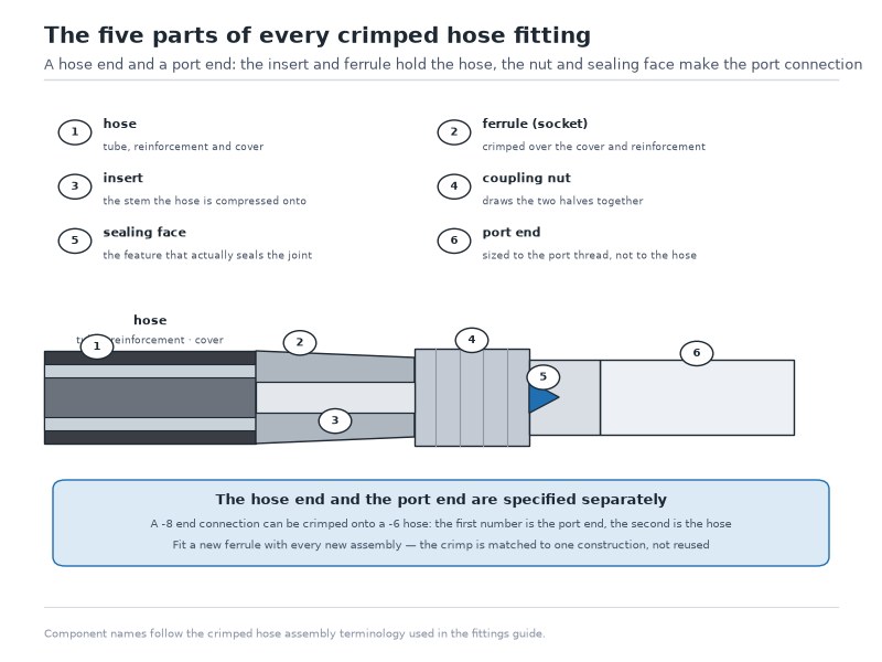
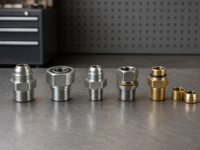
- End connections and dash ends. Each dash size has its own range of coupling and adapter sizes. A larger hose needs the matching end and, often, a port adapter at the machine. Our hydraulic fittings types guide sets out how the connection families compare and where reductions and adapters are acceptable, and our hydraulic hose sizes explained guide covers how the bore itself is defined and measured on a workshop bench.
- Bend radius. Every skip in bore size increases the published minimum bend radius. A line that was bent tightly against a frame may not be routable at the new size, and forcing the bend is the fastest way to shorten a hose’s life.
- Supports and clamps. A heavier assembly needs more support along its length and a defined gap at the first clamp, so that movement at the ports does not translate into a pulled fitting.
- Fluid volume and response. More bore means more oil in the line, which changes the volume the pump must fill on start-up and can alter the feel of a circuit.
- Pressure rating and temperature. The pressure class must still cover the relief setting and surge at the new size, and the rated pressure falls as temperature rises, which matters on a hot return line.
- Assembly qualification. Any change to bore, ends, or length moves the assembly outside its previous qualification, so the crimp or swage is set again and the finished assembly is proof tested before it goes into service. The process is covered in our hydraulic hose assembly and crimping guide.
One practical warning: it is common for a maintenance team to replace a hose with the bore of the hose it removed, which preserves an error through several generations of repairs. If a hose size selection was never verified in the first place, verifying it once — with the flow figure in hand — is cheaper than living with the consequences.
How Does Hose Size Affect Cost, MOQ, and Lead Time?
Bore size is one of the strongest cost drivers in a hose assembly, and it is the one the buyer usually fixes before anyone speaks to a supplier, which makes hose sizing a commercial decision as much as a technical one. There is no meaningful price per metre for a hydraulic hose until the assembly is defined, because cost follows the whole scope rather than the bore alone.
- Bore and pressure class. A larger bore uses more tube compound, more reinforcement wire, and larger end connections. Raising the pressure class on the same bore adds reinforcement again, so the two changes multiply.
- Length and assembly count. Cutting, fitting, and testing are partly fixed per assembly, so the same total metres split across many assemblies costs more than one long line.
- End connections. Frequently the largest single difference between two quotes on the same hose. A standard crimped coupling and a special end with an adapter are different purchases with different tooling.
- Testing and documentation. A proof test certificate, a material certificate, and a documented inspection plan are separate line items, and they belong in the comparison.
- Quantity. Standard dash sizes and common compounds are built in batches, while a mixed order of many bores, lengths, and ends spreads setup across more line items. That is where minimum order quantity and lead time usually come from, not from the hose itself (Figure 4).
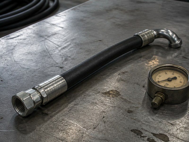
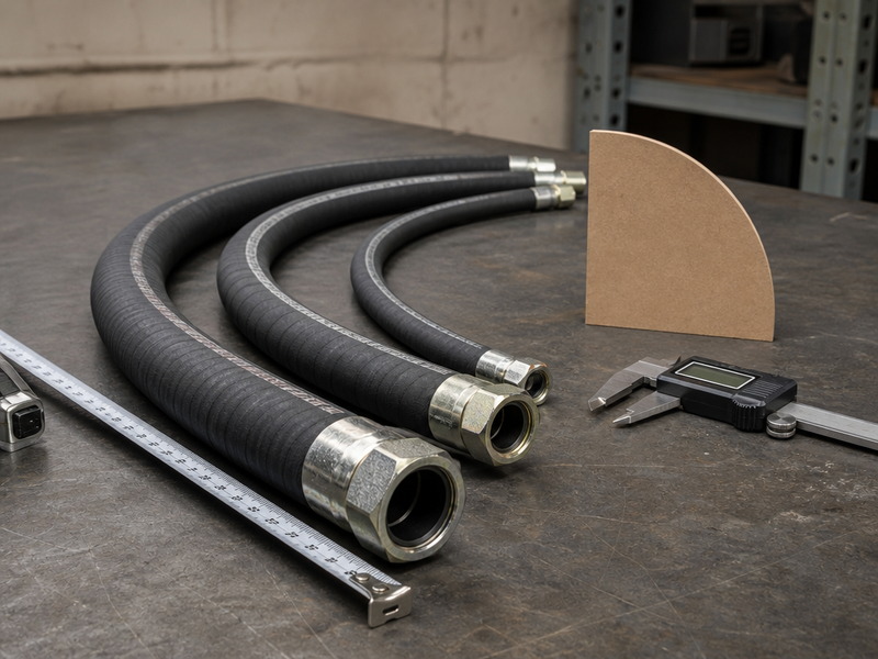
Figure 4. A finished assembly on the bench. Cost follows the whole scope — bore, pressure class, ends, test and documentation — rather than the hose alone.
The commercial consequence of sizing well is simple: the correct bore uses fewer change-overs. Standardising a machine on two or three dash sizes, and reusing approved ends, keeps quantities in the efficient range and keeps lead time predictable. Steel wire braided hydraulic hose is stocked and priced by dash size for exactly that reason, and the same logic applies to the fittings and adapters that go with it.
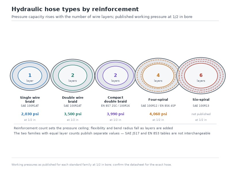
To compare offers fairly, build a comparison table with one row per requirement — bore, pressure class, length, ends, test, documentation, marking, packing, quantity, and lead time — and mark each offer as included, excluded, optional, or not stated before you compare totals. A quote that leads with a low number and omits the test certificate is the incomplete option rather than the cheaper one. If you are standardising a machine or a fleet, send us three figures — flow rate, line duty, and the dash sizes you run today — and we will confirm which two or three sizes cover the programme and quote them line by line: send your duty data. If you are sourcing for a machine programme or a fleet, our hydraulic hose guide explains how sizing, standards, and assembly decisions fit together, and the SAE 100R hose standards guide covers the construction classes behind the pressure ratings.
How Do You Verify a Hydraulic Hose Sizing Calculation on the Machine?
A calculated size is a hypothesis until the machine confirms it. The verification below takes an hour and settles the question with evidence rather than opinion.
- Confirm the hydraulic hose flow rate. Use the pump displacement and drive speed, or a flow meter at working temperature, and use the largest figure the machine can actually produce. A flow rate taken from a specification sheet rather than the pump itself is the most common source of an undersized line.
- Measure the bore. Check the ID on the manufacturer’s data sheet, and confirm it against the marking line on the hose. Nominal dash size and actual bore are not always identical between constructions.
- Recompute the hydraulic hose velocity. Run the velocity formula again with the measured flow and the real ID, and compare the result with the band for that duty. This takes two minutes and removes all doubt.
- Check the hydraulic hose pressure drop across the line. Where the circuit allows it, measure pressure at both ends of the run at maximum flow. A return-line loss far above the estimate usually means a fitting, a bend, or an obstruction rather than the bore.
- Watch the return-line temperature. Take the tank temperature after 30 minutes of normal work, and again after a hose change. A return line one dash size too small typically raises tank temperature measurably within a working session, and the temperature falls back when the bore is corrected. The hydraulic hose velocity figure will not show that, which is why the temperature check matters. As an industry practice rather than a fixed standard requirement, the size of that rise depends on flow, ambient temperature and tank volume, so the before-and-after reading on the machine is the value that counts.
- Check the suction side separately. A vacuum gauge at the pump inlet should stay low and steady. Rising vacuum points at the strainer, the inlet height, or the suction line, and it belongs to the suction hose selection question rather than to a pressure-line calculation.
- Cross-check with the nomogram. If a hose sizing nomogram and the calculation disagree, the chart is usually being read with the wrong band. Re-read the band, then trust the calculation (Figure 5).
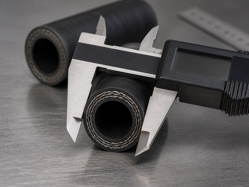
Figure 5. The measurement that settles the argument: caliper jaws inside the bore of a cut section, not across the cover.
The honest limitation is that all of this verifies the line, not the whole system. If the temperature does not respond to a hose size change, the cause is elsewhere: relief valve setting, pump condition, cooler capacity, or duty cycle. Recording the before-and-after numbers is what allows that conclusion to be reached quickly, and it is also what turns a hose size selection from a habit into a documented decision. Send the before-and-after temperature reading and the dash size you changed from, and our engineers will tell you whether the bore was the cause or whether the heat lies in the pump, the relief valve, the filter or the cooler: send the two readings.
When the sizing question is broader than one line — a new machine, a fleet standard, or a replacement programme — the sequence in our hydraulic hose selection guide puts bore, pressure, temperature, and fluid in the right order.
Hose Sizing Chart PDF: What Belongs on the Workshop Wall?
A single printed page answers most sizing questions at the machine, and it is worth building from the two tables on this page — the velocity bands and the heat-versus-pressure-loss table — rather than downloading a generic hydraulic hose size chart PDF that carries another company’s part numbers.
- The velocity bands for suction, return, medium-pressure and high-pressure lines, in ft/s and m/s, with the note that continuous duty uses the lower half of the band.
- The flow capacity limits for each dash size at the three bands the complete dash-by-dash flow column prints — 20 ft/s for pressure, 10 ft/s for return and 4 ft/s for suction — or computed at any other velocity from the formula on this page.
- The three-step method on one line: minimum bore (in) = √(0.408 × GPM ÷ v), round up to the next dash size, then check pressure drop.
- The unit conversions a mixed-unit shop needs: 1 GPM = 3.785 L/min, 1 ft/s = 0.3048 m/s, 1 bar = 14.5 psi.
- A pressure-drop check, so that the hydraulic hose pressure drop along a long run is compared with the system pressure instead of being assumed away.
Keep the sheet to one side of A4, put the flow column that matches your machine’s duty at the top, and print the revision date on the sheet. Re-issue it whenever the velocity bands, the standard the line is built to, or the dash sizes your workshop stocks change, so that a hose size selection on the shop floor comes from the current sheet rather than from memory.
Frequently Asked Questions
Is there a hydraulic hose sizing calculator that gives the right dash size?
Online sizing calculators apply the same velocity formula and the same velocity bands used in this guide, so they agree with a hand calculation whenever the inputs match. What a calculator cannot supply are the three inputs that decide the answer in practice: the fluid temperature at start-up, the real run length including fittings and bends, and the duty cycle. A calculator returns the smallest bore that holds velocity inside the band; it does not say whether the pressure drop along a long run is acceptable, or whether the outside diameter and bend radius will fit the machine. Use it for the first pass, then confirm those three points before ordering.
How do I size a hydraulic hose for a machine I am retrofitting from 15 to 25 GPM?
Take the new maximum flow — 25 GPM if the pump is being changed, or the sum of the functions that can run together if only the duty is changing — and resize every line on it, not just the pressure line. At 25 GPM a -12 (0.75 in) line carries 18.1 ft/s (5.5 m/s): inside the 15–20 ft/s band for a pressure line, but above the 10–15 ft/s return band, so a return line steps up to -16 (1.0 in) at 10.2 ft/s (3.1 m/s). The suction line usually steps up two sizes from its original. Confirm the new dash size against the port, the bend radius and the existing clamps before the hose is ordered.
What is the hydraulic pipe size equivalent of a -12 hose?
A -12 hose has a nominal bore of 3/4 in (19.05 mm), which sits between two nominal pipe sizes rather than matching one: 1/2 in NPS pipe has a schedule 40 bore near 0.622 in and 3/4 in NPS pipe about 0.824 in. Pipe and tube are chosen from inside diameter and wall thickness against a pressure and corrosion duty, while hose is chosen from dash size and construction, so converting one to the other is a comparison rather than a substitution. Size the hose from the flow and the velocity band first, then match the end connections to the port at each end.
What size hydraulic hose do I need for 20 GPM?
At 20 GPM (75.7 L/min) the pressure line lands on -12 (3/4 in, DN19) at 14.5 ft/s (4.4 m/s) and the return line on the same size at the top of its band, while the suction line needs -24 (1.5 in, DN38) to stay near 3.6 ft/s (1.1 m/s). Two checks decide whether those three sizes hold on a specific machine: the largest flow the pump can actually produce at working temperature, which is often above the nominal figure, and the duty cycle, because a line running continuously at full flow is sized on the lower half of its band.
How do I know if my hydraulic hose is too small?
Measure rather than guess: take the flow at working temperature, read the bore from the layline or the data sheet, and compute velocity for that line duty. A suction line above 4 ft/s (1.2 m/s), a return line above 15 ft/s (4.6 m/s) or a pressure line above 25 ft/s (7.6 m/s) is outside its band and is the first thing to change. Where the calculation sits inside the band and the tank still runs hot, the loss is usually in a fitting, a bend or a partly blocked strainer, and a larger hose masks the symptom rather than removing it.
Does a bigger hose always run cooler?
A larger hose lowers the velocity and the pressure loss in that line, so it lowers the heat generated there — and it does so at a cost in fluid volume, weight, bend radius and price. Where the extra heat comes from a passing relief valve, a worn pump, a blocked return filter or an undersized cooler, changing the hose leaves the tank temperature where it was. Measure tank temperature before and after a hose change so the result is attributable to the change you made.
Final Verdict on Hydraulic Hose Sizing
Hydraulic hose sizing is a two-minute calculation that prevents a two-year problem. Fix the maximum hydraulic hose flow rate, choose the velocity band for the line duty, use the formula or the flow capacity table to find the minimum bore, round up to the next standard dash size, then verify pressure drop, bend radius, and envelope before you order. Check the result on the machine with a temperature reading and, where possible, a pressure measurement at both ends of the run.
The working rules are short enough to remember: suction lines run in the 2–4 ft/s band, return lines 10–15 ft/s, medium-pressure lines 15–20 ft/s, and high-pressure lines 20–25 ft/s, with the bottom half of each band reserved for continuous duty. Any hose size selection that ignores those bands is running on habit rather than on data, and the cost of that habit is paid slowly in heat, oil, and pump life.
Minimum information by reader, and what the reply answers
| You are… | Send at minimum | What you get back |
|---|---|---|
| Sizing a new machine | flow rate, line duty, working pressure | bore, pressure class, construction |
| Fixing a hot or slow machine | dash size in use now, flow rate, tank temperature | whether the bore is the cause or the heat lies elsewhere |
| Buying for a programme or a fleet | standard family, dash sizes, quantities, documentation | a line-by-line quote with test and packing |
HENGHUA engineers work through sizing questions every day for machine builders, fleets, and replacement stock programmes. If you are specifying hose for a machine programme, a fleet, or a stock list, send us the flow rate, line duty, working pressure, temperature range, run length, fluid type, and the dash size you run today. We will confirm the bore, the pressure class, and the construction, then quote line by line — hose, ends, testing, documentation, packing, and lead time — so that a hydraulic hose sizing decision rests on numbers rather than on habit. Contact HENGHUA for a quote and free samples.
 English
  Spanish
  Portuguese
  French
  German
  Arabic