
Why This 45 Degree Code 62 Flange Elbow Passes the Compliance Gate
When a high-pressure line must turn through a tight offset, code 62 flange fittings in a 45 degree elbow keep the routing compact and the joint reliable. The HENGHUA 87641 series is a 45 degree elbow SAE flange 6000 psi hydraulic hose fitting: the Code 62 head is machined to SAE J518 / ISO 6162-2, and the hose end follows ISO 12151-3 / SAE J516 as printed on the series sheet. Ten standard part numbers cover flange sizes from 1/2 inch to 2 inch with hose bores from DN 12 to DN 50 (dash -08 to -32).
For OEMs, the 45 degree geometry clears valve pads and pump ports where a straight fitting would not fit. For distributors, this one elbow series answers most code 62 flange fitting requests without specials. For maintenance teams, the four-bolt flange face makes replacement predictable and fast.
- SAE J518 Code 62 head, the 6,000 psi class in the SAE 6000 psi flange fittings family
- 45 degree elbow geometry for smooth redirection with less pressure loss than a 90 degree bend
- Ten braided-hose combinations from 1/2 inch to 2 inch flange, -08 to -32 hose dash
- Spiral-hose version available under the series number printed on the dimension sheet
- 100% pressure tested at the HENGHUA factory before packing
Core Advantages
- Space-saving 45 degree route. The elbow turns the hose gradually, so the assembly fits tight machine compartments and keeps the hose above its minimum bend radius.
- True 6000 psi class. This code 62 flange fitting uses the SAE J518 heavy-series head for high-pressure service and is factory pressure tested before shipment.
- Ten sizes, one series. Flange sizes 1/2, 3/4, 1, 1.1/4, 1.1/2 and 2 inch match the ISO 6162-2 envelope, so planning and stock control stay simple.
- Corrosion protection options. Trivalent zinc, zinc-nickel or Dacromet finishes match the working environment, from dry indoor plants to offshore and mining sites.
Technical Specifications
What Is a 45 Degree Code 62 Flange Fitting?
A 45 degree code 62 flange fitting is a high-pressure hose terminal whose flange head sits at 45 degrees to the hose axis. The head is clamped to a mating pad or valve port by a two-piece split flange and four bolts, which is why the connection is also called a four-bolt flange. Code 62 is the 6,000 psi class defined in ISO 6162-2 and SAE J518, while Code 61 is the lighter 3,000 psi class with different flange dimensions; the two are never interchangeable. The SAE J518 Code 62 envelope is dimensionally distinct from Code 61, so heads and clamp sets never cross.
The elbow saves space where a straight fitting plus a separate hose bend would need extra clearance, and it avoids the sharp flow turn of a 90 degree elbow. The hose end of the 87641 series is a barbed stem sized for braided hydraulic hose and crimped with a standard machine. Because the joint seals on an O-ring instead of a tapered thread, it tolerates vibration and repeated assembly better than many threaded connections of the same size. As one of the flange type hydraulic hose fittings in the HENGHUA range, the 87641 is matched to split flange clamps from the same Code 62 system.
Dimensional Data
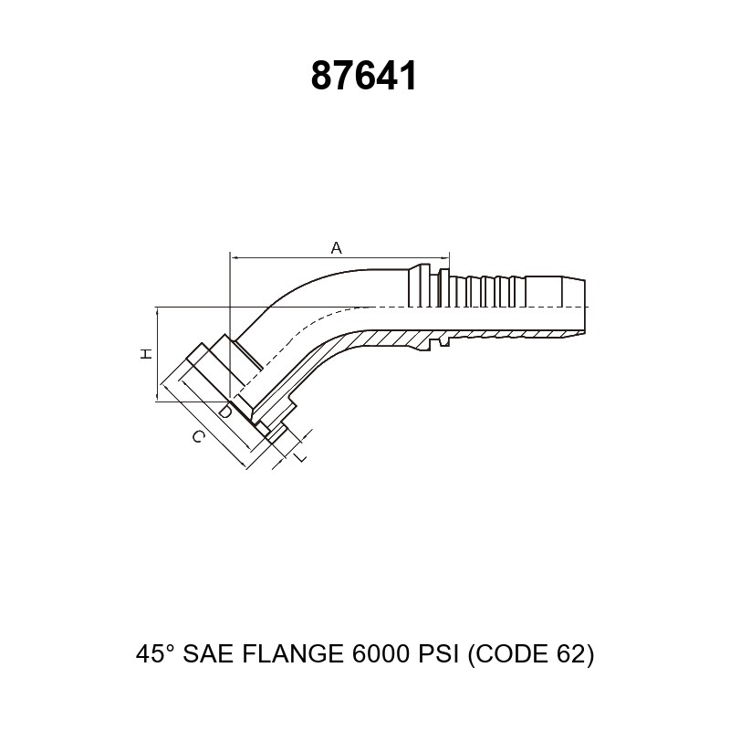
The letters in the drawing and in the table below follow the dimension sheet for the 87641 series. Every code 62 flange fitting in the matrix is controlled by the five dimensions below, and all SAE flange fitting dimensions printed on the sheet are reproduced here in millimeters (mm).
| Symbol | Description |
|---|---|
| A | Horizontal length from the flange axis to the far end of the hose tail |
| H | Center height from the hose centerline to the flange face, as dimensioned on the series drawing |
| C | Outer diameter of the flange head |
| D | Diameter of the neck/shoulder behind the flange head |
| L | Thickness of the flange head |
Full Dimension Table (Part Number Matrix)
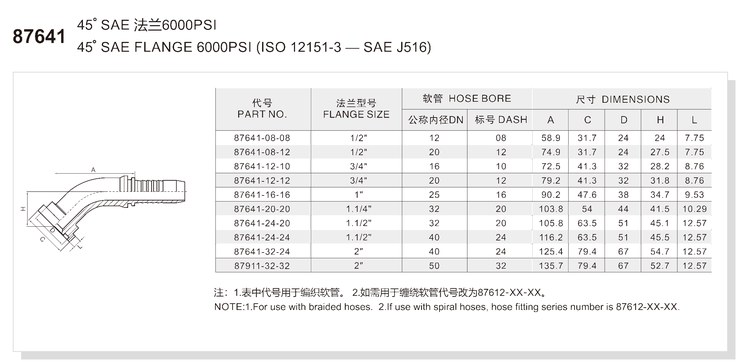
Read the table left to right. The part number is built as series-flange-hose, for example 87641-16-16 means the 87641 series with a 1 inch (dash -16) flange and a hose bore of dash -16 (DN 25). Dimensions A, C, D, H and L are in millimeters. The table below is a faithful transcription of the HENGHUA dimension sheet; if your layout requires values that are not listed, request the full engineering drawing with your quote. Every row is a complete code 62 flange fitting with the flange and hose fields already matched.
| PART NO. | FLANGE SIZE | HOSE BORE (DN) | HOSE BORE (DASH) | A | C | D | H | L |
|---|---|---|---|---|---|---|---|---|
| 87641-08-08 | 1/2″ | 12 | 08 | 58.9 | 31.7 | 24 | 24 | 7.75 |
| 87641-08-12 | 1/2″ | 20 | 12 | 74.9 | 31.7 | 24 | 27.5 | 7.75 |
| 87641-12-10 | 3/4″ | 16 | 10 | 72.5 | 41.3 | 32 | 28.2 | 8.76 |
| 87641-12-12 | 3/4″ | 20 | 12 | 79.2 | 41.3 | 32 | 31.8 | 8.76 |
| 87641-16-16 | 1″ | 25 | 16 | 90.2 | 47.6 | 38 | 34.7 | 9.53 |
| 87641-20-20 | 1.1/4″ | 32 | 20 | 103.8 | 54 | 44 | 41.5 | 10.29 |
| 87641-24-20 | 1.1/2″ | 32 | 20 | 105.8 | 63.5 | 51 | 45.1 | 12.57 |
| 87641-24-24 | 1.1/2″ | 40 | 24 | 116.2 | 63.5 | 51 | 45.5 | 12.57 |
| 87641-32-24 | 2″ | 40 | 24 | 125.4 | 79.4 | 67 | 54.7 | 12.57 |
| 87641-32-32 | 2″ | 50 | 32 | 135.7 | 79.4 | 67 | 52.7 | 12.57 |
Note printed on the series dimension sheet: 1. For use with braided hoses. 2. If use with spiral hoses, hose fitting series number is 87612-XX-XX. Because series sheets occasionally vary, HENGHUA confirms the correct spiral-series number with every spiral-hose inquiry.
Material and Heat Treatment
| Property | Standard Offer |
|---|---|
| Body material | High-strength cold-forged or hot-forged carbon steel (20# / 35# / 45#), or 304 / 316L stainless steel on request |
| Heat treatment | Carburized and quenched; core hardness HRC 20-28 with batch hardness records |
| Surface finish | Trivalent zinc (96 h salt spray), zinc-nickel (720 h) or Dacromet (1000 h), selected by working environment |
| Inspection | 100% dimensional and pressure testing; thread gauges used where threads are present |
Working Pressure and Operating Envelope
The envelope below describes SAE J518 code 62 flange fittings as a connection class; the working pressure of a finished assembly is always limited by the hose rating and the crimp specification.
| Parameter | Value |
|---|---|
| Flange class | Code 62 per SAE J518 / ISO 6162-2, nominal 6,000 psi |
| Assembly working pressure | Governed by the hose rating and the crimp specification; confirm with your hose data |
| Factory test | 100% pressure test of every fitting before packing |
| Temperature range | Typical -40 degree C to +120 degree C; system derating is set by hose and seal materials |
Selection and Ordering
How to Read the Part Number Matrix
The 87641 part number has three fields: 87641 – flange size – hose size. Both numeric fields use the dash convention where each dash number equals 1/16 inch, so a 1/2 inch flange reads as -08 and a 1 inch flange reads as -16. For a flange type hydraulic hose fitting like this series, the two numeric fields define the whole interface, so cross-check the FLANGE SIZE and HOSE BORE columns against your hose and port before ordering. The H column of the matrix gives the center height you need for envelope planning, and all SAE flange fitting dimensions in the matrix are in millimeters.
Flange Size and Dash Size Chart
| FLANGE SIZE | FLANGE DASH | HOSE DASH COMBINATIONS COVERED | HOSE BORE DN |
|---|---|---|---|
| 1/2″ | -08 | -08, -12 | DN 12, 20 |
| 3/4″ | -12 | -10, -12 | DN 16, 20 |
| 1″ | -16 | -16 | DN 25 |
| 1.1/4″ | -20 | -20 | DN 32 |
| 1.1/2″ | -24 | -20, -24 | DN 32, 40 |
| 2″ | -32 | -24, -32 | DN 40, 50 |
Cross Reference Service
Do you maintain equipment whose original flange elbow carries a legacy or OEM part number? Send HENGHUA the old number, the flange size, the hose bore and a photo or drawing, and our engineers will identify the matching 87641 series part. The service is free and answers within one working day, so you can convert obsolete references to current, orderable SAE 6000 psi flange fittings without trial assemblies. The 45 degree angle and the H dimension in your drawing are the two details that pin the exact match.
Packaging and Logistics
| Item | Standard Practice |
|---|---|
| Inner packing | 10 pcs per box, separated to prevent surface damage |
| Carton | Corrugated cartons palletized for sea or air freight |
| Labeling | Batch label on every box with series number, size and quantity |
| Batch marking | Batch code traceable to material heat and inspection records |
| Country of origin | Made in China, HENGHUA factory |
| Documents | MTR available on request; BV/SGS third-party inspection can be arranged |
Assembly and Use Guide
Four-Step Crimping Procedure
- Cut the hose square with a sharp cutter; a clean 90 degree end protects the inner tube and the seal.
- Mark the insertion depth on the hose outer cover with the depth mark from the crimp data sheet.
- Apply a thin layer of assembly lubricant and push the hose onto the stem until it reaches the mark.
- Crimp with the die set specified for this series, then verify the crimp outer diameter with a caliper against the value on the data sheet.
Orient the elbow before crimping so the flange face is parallel with the mating pad; once the ferrule is compressed, the elbow angle is fixed. The crimp data sheet is provided with every order.
Mounting the Flange Connection
- Align the flange head squarely with the mating pad and check that the port face is clean.
- Seat the O-ring in the groove on the flange head or in the port counterbore, per your clamp kit drawing.
- Place the two split flange halves over the head and insert the four bolts with the washers supplied in the clamp kit.
- Tighten the bolts in a diagonal sequence, in two or three passes, to the torque given in the flange clamp data sheet.
Like every flange type hydraulic hose fitting, the 87641 needs its matching clamp set and O-ring. Bolts, split flange clamps and O-rings are ordered separately and matched to the Code 62 flange size.
Installation Warnings
- Do not mix fittings, hose ends or ferrules from different manufacturers in one crimp assembly; dimensional systems differ even when they look alike.
- Braided-hose fittings and spiral-hose fittings are not interchangeable. Use the series printed on the dimension sheet for your hose type.
- Bolts for the flange clamp are not included with the fitting. Order the correct Code 62 bolt kit for the flange size.
- A crimped fitting cannot be reworked. If the crimp diameter is out of tolerance, cut off the ferrule and start with a new fitting.
- Always verify the O-ring is present and undamaged before assembly; the O-ring is the sealing element of the whole joint.
OEM Customization and Quality Traceability
Customization Options
The 87641 series is available with OEM-specific options on volume orders. Elbow offset and stem length can be adapted to your assembly drawings, and surface finish can be switched between trivalent zinc, zinc-nickel and Dacromet. Laser marking adds your logo, series and batch code, and 304 or 316L stainless steel can be substituted for carbon steel in corrosive environments.
Quality and Traceability System
Every batch follows the same flow: incoming material check, cold forging, machining, heat treatment, surface finishing, 100% inspection, pressure testing, marking and packing. A batch code on the box links back to the material heat number, the heat-treatment records and the inspection reports. MTR certificates accompany orders on request, and BV/SGS third-party inspection can be scheduled before shipment.
FAQ
What standard is the 87641 45 degree code 62 flange elbow built to? The flange head follows SAE J518 / ISO 6162-2 (Code 62), and the hose end follows ISO 12151-3 / SAE J516 as referenced on the series sheet.
What pressure rating does the 87641 series have? Code 62 is the 6,000 psi flange class, the high-pressure member of the SAE 6000 psi flange fittings family. The finished hose assembly is limited by the hose rating and the crimp specification, so confirm the working pressure with your hose data sheet.
When should I choose a 45 degree elbow instead of a 90 degree elbow? Use 45 degrees for gentle redirection and tighter vertical offsets. The 45 degree elbow creates less flow disturbance than a 90 degree bend and keeps the hose closer to its natural routing line.
Is the 87641 for braided or spiral hose? The table lists code 62 flange fittings for braided hose. For spiral-wound hose, use the spiral series number confirmed by HENGHUA, as noted under the dimension table.
Which dimension is the elbow offset height? The H column in the matrix is the center height from the hose centerline to the flange face. Check it against your machine envelope together with dimension A; full SAE flange fitting dimensions are listed in the matrix above.
How is the flange sealed? Sealing is by O-ring between the flange face and the mating port, compressed by the split flange clamp and four bolts. Keep the groove clean and fit a new O-ring at every reassembly.
Are bolts and split flange included with the fitting? No. The fitting is the hose-end terminal; split flange clamps, bolts and O-rings are matched separately to the Code 62 flange size.
What is the lead time and how do I get a sample? Quotes are answered within 24 hours, and samples ship worldwide. Send the part number, quantity and destination port to get a confirmed lead time.
Request a Quote
Send us the part number from the matrix, the quantity and the hose type, and you will receive a quotation within 24 hours. OEM customers can attach drawings or legacy part numbers for cross-reference, and every order includes the crimp data sheet for the series. Samples are available for evaluation before volume ordering, with BV/SGS inspection and MTR documentation on request.
Browse the full Flange Fittings range for the complete family, or contact us to request a quote, mill test reports, and samples.


 English
  Spanish
  Portuguese
  French
  German