

Why This 90 Degree Elbow Fittings Adapter Passes the Compliance Gate
A 90 degree elbow fittings adapter is judged by three things: whether the 24° cone seat actually seals without sealer, whether the thread and cone dimensions match the standard the buyer’s manifold was machined to, and whether the lot can be traced back to a heat number. Every 1C9/1D9 elbow that leaves our plant ships with a dimensional inspection report on the 24° cone angle, the thread gauge result (6H/6g go–no-go), the hex across-flats and the through-bore, plus an EN 10204 3.1 material certificate on request. For an approved vendor list, that means the part you qualify on the first article is the part you receive on the tenth order.
The 1C9/1D9 family is the metric, 24° cone branch of our elbow range: a one-piece forged body with a metric male 24° cone (DIN 2353 / ISO 8434-1) end on each leg, arranged at 90°. The “C” prefix is the L (light) series; the “D” prefix is the S (heavy) series. The two series share tube outside diameters but use different threads and wall thicknesses, which is why the same 6 mm tube appears as 1C9-12 (M12×1.5) and as 1D9-14 (M14×1.5) in the tables below.
Core Advantages
- One elbow instead of two fittings. A 90° elbow replaces a straight stud end plus a swivel elbow, removing one threaded joint — and therefore one potential leak path and one extra pressure-drop point — from every corner of the circuit.
- Metal-to-metal 24° cone seat. Sealing happens on the cone, not on an elastomer, so the joint tolerates high temperature, aggressive fluids and the shock loading typical of mobile hydraulics.
- Full L and S coverage from one tooling family. Tube 6 mm to 42 mm, light series to 31.5 MPa, heavy series to 63 MPa, all with matching hex and reach dimensions.
- No welds in the pressure boundary. Bodies are forged, drilled and machined from bar or closed-die blanks; nothing is fabricated or brazed.
- Traceable in both directions. Heat number, heat-treatment batch and plating batch are recorded against the sales order, so a field query can be answered with data, not with an assumption.
Especificaciones técnicas
What Is a 90 Degree Elbow Fittings Adapter?
It is a 90° directional adapter for hydraulic tube systems built to the metric 24° cone system (DIN 2353 / ISO 8434-1, equivalent to GB/T 3733-2008). Both ends are metric male with an external 24° cone and a straight metric thread, so the fitting screws into two ports, or into a port and a tube nut, and turns the flow through a right angle.
Connection 1 and Connection 2 — Metric Male 24° Cone
Both ends are metric male 24° cone stud ends. The cone contacts a matching 24° internal cone in the port, or a sleeve/nut pair on the tube side, and the seal is made by the elastic and plastic deformation of the two cone faces as torque is applied. There is no O-ring and no captive seal in this design, which is deliberate: it is the configuration that survives the widest range of process fluid, temperature and contamination.
Because both ends are metric, the 1C9/1D9 family does not mate with 60° cone (BSP/DIN 3861) or 37° flare (JIC/SAE 37°, ISO 8434-2) ports. The three cone geometries are not interchangeable: 24°, 60° and 37° seats have different included angles, contact diameters and thread forms. Mixing them produces a line-contact or edge-contact at the cone, a joint that passes a static test and then weeps under thermal cycling. Confirm the port angle before ordering.
Dimensional Data
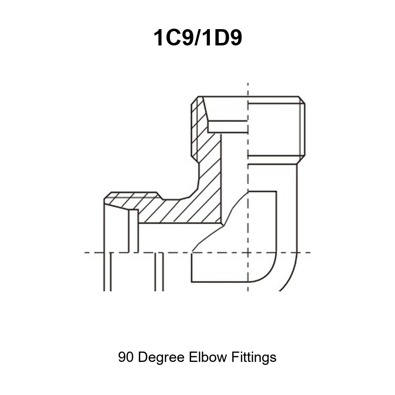
In the drawing, E and F are the thread designations of the two legs, D1 and D2 the tube outside diameters, l1/l2 the reach from the thread end face to the leg centreline, L1/L2 the overall length of each leg measured along its own axis, and S1/S2/S3 the hex across-flats used for wrenching.
For an elbow, the two leg lengths are measured along two perpendicular axes. They are not symmetric and they are not interchangeable: rotating the body to gain clearance on the manifold side changes the stack height on the tube side. When an elbow is used inside a machined manifold block or under a valve bank, check both the horizontal length (L) and the vertical height (H) of the leg before ordering — the drawing view that dimensions L and H is the orientation you must reproduce in the installation.
Full Dimension Table (Part Number Matrix)
Values as published in the HENGHUA catalogue drawing. Dimensions in millimetres.
| PART NO. | THREAD E | THREAD F | D1 | D2 | l1, l2 | L1, L2 | S1 | S2, S3 | Pressure MPa |
|---|---|---|---|---|---|---|---|---|---|
| 1C9-12 | M12×1.5 | M12×1.5 | 6 | 6 | 12 | 27 | 12 | 14 | 31.5 — L series |
| 1C9-14 | M14×1.5 | M14×1.5 | 8 | 8 | 14 | 29 | 12 | 17 | 31.5 — L series |
| 1C9-16 | M16×1.5 | M16×1.5 | 10 | 10 | 15 | 30 | 14 | 19 | 31.5 — L series |
| 1C9-18 | M18×1.5 | M18×1.5 | 12 | 12 | 17 | 32 | 17 | 22 | 31.5 — L series |
| 1C9-22 | M22×1.5 | M22×1.5 | 15 | 15 | 21 | 36 | 19 | 27 | 31.5 — L series |
| 1C9-26 | M26×1.5 | M26×1.5 | 18 | 18 | 23.5 | 40 | 24 | 32 | 31.5 — L series |
| 1C9-30 | M30×2 | M30×2 | 22 | 22 | 27.5 | 44 | 27 | 36 | 31.5 — L series |
| 1C9-36 | M36×2 | M36×2 | 28 | 28 | 30.5 | 47 | 36 | 41 | 16 — L series |
| 1C9-45 | M45×2 | M45×2 | 35 | 35 | 34.5 | 56 | 41 | 50 | 16 — L series |
| 1C9-52 | M52×2 | M52×2 | 42 | 42 | 40 | 63 | 50 | 60 | 16 — L series |
| 1D9-14 | M14×1.5 | M14×1.5 | 6 | 6 | 16 | 31 | 12 | 17 | 63 — S series |
| 1D9-16 | M16×1.5 | M16×1.5 | 8 | 8 | 17 | 32 | 14 | 19 | 63 — S series |
| 1D9-18 | M18×1.5 | M18×1.5 | 10 | 10 | 17.5 | 34 | 17 | 22 | 63 — S series |
| 1D9-20 | M20×1.5 | M20×1.5 | 12 | 12 | 21.5 | 38 | 17 | 24 | 63 — S series |
| 1D9-22 | M22×1.5 | M22×1.5 | 14 | 14 | 22 | 40 | 19 | 27 | 63 — S series |
| 1D9-24 | M24×1.5 | M24×1.5 | 16 | 16 | 24.5 | 43 | 24 | 30 | 63 — S series |
| 1D9-30 | M30×2 | M30×2 | 20 | 20 | 26.5 | 48 | 27 | 36 | 40 — S series |
| 1D9-36 | M36×2 | M36×2 | 25 | 25 | 30 | 54 | 36 | 46 | 40 — S series |
| 1D9-42 | M42×2 | M42×2 | 30 | 30 | 35.5 | 62 | 41 | 50 | 40 — S series |
| 1D9-52 | M52×2 | M52×2 | 38 | 38 | 41 | 72 | 50 | 60 | 31.5 — S series |
Rows beyond the printable area of the source scan are marked [to be confirmed] in the internal data sheet; the part numbers above are the complete published 1C9/1D9 range.
Thread Size and Dash Chart
| Tube OD (D1, D2) | L series (1C9) thread | S series (1D9) thread |
|---|---|---|
| 6 mm | M12×1.5 | M14×1.5 |
| 8 mm | M14×1.5 | M16×1.5 |
| 10 mm | M16×1.5 | M18×1.5 |
| 12 mm | M18×1.5 | M20×1.5 |
| 14 mm | — | M22×1.5 |
| 15 mm | M22×1.5 | — |
| 16 mm | — | M24×1.5 |
| 18 mm | M26×1.5 | — |
| 20 mm | — | M30×2 |
| 22 mm | M30×2 | — |
| 25 mm | — | M36×2 |
| 28 mm | M36×2 | — |
| 30 mm | — | M42×2 |
| 35 mm | M45×2 | — |
| 38 mm | — | M52×2 |
| 42 mm | M52×2 | — |
The pattern is standard DIN 2353: the heavy (S) series uses one thread size larger than the light (L) series for the same tube OD, which is how the heavier wall tube is accommodated without changing the cone system.
Material and Heat Treatment
Standard production bodies are carbon steel (20# / 45# equivalent), forged or machined from bar, then case-hardened or through-hardened according to the pressure class, with a trivalent-chromium or zinc-nickel plated finish. Stainless steel 304, 316 and 316L are available as a non-standard option for offshore, food-grade and de-icing applications. Carbon-steel parts receive a corrosion protection layer in the 96–720 h neutral salt-spray band depending on the agreed specification.
Working Pressure and Operating Envelope
Pressure ratings in the table are working pressures for the L and S series per the relevant standard, not burst pressures. A representative burst-to-working ratio of 4:1 applies to the body. Pressure is limited by the weaker of the two legs, by tube wall thickness and by the mating port; the correct practice is to size the whole circuit, not the fitting alone.
Rango de temperatura
NBR elastomer, where used on associated seals, covers −40 °C to +120 °C. FKM covers −20 °C to +200 °C. The 24° cone joint itself is not temperature-limited by an elastomer, but thread lubricant and plating selection should be reconsidered above +150 °C.
How to Read the Part Number Matrix
1C9-12 = family 1C9 (metric male 24° cone elbow, L series), size 12 = tube 6 mm / M12×1.5. 1D9-14 = same geometry in the S series, size 14 = tube 6 mm / M14×1.5. The numeric suffix is the catalogue size, not the tube OD in millimetres, and it moves with the series. When cross-referencing an OEM part number, quote the tube OD and the thread, plus the pressure class; that combination is unique inside this family.
Selection and Ordering
Selection Checklist / Decision Table
| Requirement | Choose |
|---|---|
| Tube 6–22 mm, working pressure ≤ 31.5 MPa | 1C9 (L series) |
| Tube 6–16 mm, working pressure up to 63 MPa | 1D9 (S series) |
| Tube 20–30 mm, up to 40 MPa | 1D9 (S series) |
| Tight manifold, hex must be small | L series |
| High vibration, heavy wall tube | S series |
| Corrosive environment | 304 / 316L on request |
Cross Reference Service
Send us the OEM number, the tube OD, the thread callout or a photograph of the port and we will return a mapped part number with the drawing dimensions filled in. Reverse-engineering from a sample is routine: we measure the 24° cone, the pitch diameter and the hex, and confirm against the standard table.
Packaging and Logistics
Standard export packing is a plastic bag, a carton and a pallet, with anti-corrosion paper inside. Bulk orders ship with the dimensional report, the material certificate and the packing list referenced to the same heat number. Air, sea and express channels are all available depending on lead time.
Installation and Fitment Guide
Step-by-Step Assembly
- Verify the port is a metric male 24° cone port (DIN 2353 / ISO 8434-1) or a matching 24° female cone.
- Inspect and clean the cone and the port seat; remove swarf, sealant residue and paint.
- Lubricate the thread lightly with a compatible hydraulic oil or anti-seize — never apply sealant to the cone.
- Hand-start the thread to avoid cross-threading; the metric thread is fine-pitch and unforgiving.
- Hold the body with the correct hex (S dimension) and tighten to the specified torque with a calibrated wrench.
- Re-check after the first thermal cycle and at the first scheduled service.
Torque and Sealing Notes
Torque is a function of thread size, cone diameter and plating, not of how hard the wrench can be pulled. Under-torque leaves the cone short of full contact and the joint weeps; over-torque expands the port and stretches the thread, which is a permanent, unrecoverable defect on a manifold. Use a torque table issued against the actual part number and material, and use a torque wrench on every joint that holds pressure.
Installation Warnings
- Do not mix 24° cone, 60° cone and 37° flare components; the three systems look similar at a glance and never seal against each other.
- Do not use PTFE tape or thread compound as a substitute for a correct cone seat.
- Do not hold the elbow by the body when tightening a tube nut on the other leg; use two wrenches.
- Do not reuse a cone that has been over-torqued or mechanically damaged.
Applications and Industries
Typical installations include mobile hydraulic manifolds, agricultural implement circuits, injection-moulding machine power packs, machine-tool hydraulics, hydraulic power units, ship deck machinery, mining equipment and test benches. The 90 degree elbow fittings adapter is most often chosen where a hose run would otherwise kink at a corner, or where a manifold block needs to turn the flow inside a tight envelope.
OEM Customization and Quality Traceability
We produce to drawing: non-standard leg lengths, special hex, different tube ends, alternative materials and customer plating specifications. The quality route is incoming material verification, first-article inspection, in-process thread and cone gauging, pressure proof testing on sample batches, and final inspection before packing. Documentation is released against the purchase order and retained so that any part number can be reconstructed years later.
FAQ
Can I use 1C9 and 1D9 together in one circuit? Yes — they are the same 24° cone system in two wall classes. What matters is that each individual joint matches the thread and cone of its own port.
Does the 1C9 fit to a BSP port? No. BSP (60° cone, DIN 3861 / ISO 1179) and 24° metric cone are different seat geometries. Use the BSP family for that port.
Do I need an O-ring? Not with this design. Sealing is by the 24° metal cone. If your port is an ISO 6149 / ISO 11926 O-ring stud port, select a different family.
What is the difference between 1C9-12 and 1D9-14? Tube size. Both are for 6 mm tube, but 1C9-12 uses M12×1.5 (L, 31.5 MPa) and 1D9-14 uses M14×1.5 (S, 63 MPa).
Can you supply stainless steel? Yes, 304 and 316/316L, machined to the same drawing.
How is the elbow oriented in service? By rotating the body before final tightening. Confirm both leg lengths (L and H) against the installation envelope first.
Solicitar un presupuesto
Send the part number, tube OD, thread, material, quantity and any drawing or sample photograph. We will confirm the 24° cone configuration, the pressure class and the lead time, and return a quotation with the inspection and certification documents listed.
Related products in this range: 90° elbow BSPT male adapter 1CT9-SP/1DT9-SP · 90° elbow bulkhead fittings adapter 6C9/6D9 · 90° elbow reducer tube adaptor with swivel nut 2C9/2D9 · equal tees AC/AD · branch tee fittings with swivel nut BC/BD.
Browse the full Hydraulic Adapters range for the complete family, or contact us to request a quote, mill test reports, and samples.



 English
  Spanish
  Portuguese
  French
  German