
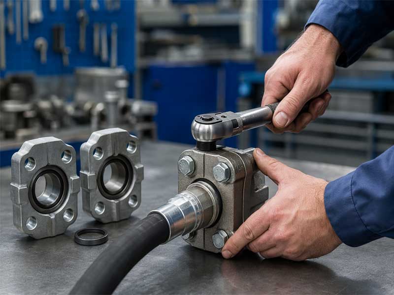
How to Install Code 61 and Code 62 Split Flange Hydraulic Fittings
Installing Code 61 and Code 62 split flange hydraulic fittings requires five steps:
- Select the correct flange code for your system’s pressure class.
- Install a new, lubricated O-ring in the flange groove.
- Clean all sealing surfaces to remove any contamination.
- Tighten the four bolts evenly using a diagonal cross-pattern torque sequence.
- Pressure-test the connection before system operation.
Never mix Code 61 and Code 62 components because their dimensions and pressure ratings are different.
1. What Are Code 61 and Code 62 Split Flanges?
Split flange fittings, also known as 4-bolt flange fittings, are a robust method for connecting hydraulic hoses, tubes, and components in high-pressure fluid power systems. They consist of two split halves that clamp around a flange head or adapter, compressing an O-ring against a mating surface to create a leak-free seal. They are also commonly called SAE J518 hydraulic flange connections or ISO 6162 four-bolt flange assemblies, reflecting their governing standards.
Understanding the distinction between the two common codes is the first and most vital step in the installation process.
2. How to Identify Code 61 vs. Code 62 Split Flanges
A common challenge for engineers and maintenance technicians is visually identifying which flange code they are working with. This is critical, as using the wrong code leads to incompatible connections.
You can differentiate between them using these physical checks:
- Check the Flange Marking: Most flanges are stamped with the code designation (e.g., “61” or “62”) and size.
- Measure Flange Thickness: Code 62 flanges are physically thicker than Code 61 flanges of the same size. This extra material provides the strength required for higher pressures.
- Check Bolt Diameter: Code 62 flanges use larger diameter bolts to handle the increased clamping force.
- Confirm the Standard: Code 61 conforms to ISO 6162-1 / SAE J518, while Code 62 conforms to ISO 6162-2.
Quick Identification Guide
| Identification Method | Code 61 | Code 62 |
|---|---|---|
| Estándar | ISO 6162-1 / SAE J518 | ISO 6162-2 / SAE J518 |
| Flange Thickness | Estándar | Thicker |
| Bolt Diameter | Smaller | Larger |
| Pressure Class | Standard pressure | High pressure |
3. Code 61 vs. Code 62 Split Flange: A Detailed Comparison
The table below outlines the primary differences to aid in correct selection.
| Feature | Code 61 (Standard Pressure) | Code 62 (High Pressure) |
|---|---|---|
| Estándar | ISO 6162-1 / SAE J518 | ISO 6162-2 / SAE J518 |
| Pressure Class | Commonly used for applications up to the 3000 psi (21 MPa) class | Commonly used for applications up to the 6000 psi (42 MPa) class |
| Primary Application | Industrial hydraulics, machine tools, standard systems | Heavy equipment, mobile hydraulics, high-output systems |
| Flange Thickness | Estándar | Thicker, for higher strength |
| Bolt Size | Smaller diameter | Larger diameter |
| Cost | Lower | Higher |
Important Note on Pressure Ratings: While Code 61 flanges are generally used for standard-pressure applications and Code 62 for high-pressure, the actual maximum working pressure depends on the specific flange size, material, bolt specification, and manufacturer’s rating. Always consult the manufacturer’s technical data for the exact rating of your component.
4. Tools Required for Proper Installation
| Tool/Equipment | Objetivo |
|---|---|
| Calibrated Torque Wrench | To apply precise and even bolt torque. |
| Hex Socket Set | To drive the flange bolts without rounding them. |
| Lint-Free Wipes & Solvent | To clean sealing faces and O-ring grooves. |
| O-Ring Lubricant | To prevent pinching or rolling during assembly. |
| Inspection Mirror | To visually check hard-to-see sealing surfaces. |
| Pressure Gauge | To monitor and validate system pressure during testing. |
5. Step-by-Step Installation Procedure for 4-Bolt Split Flange Fittings
Step 1: Component Inspection and Selection
- Check the O-ring: Inspect for any cuts, abrasions, or hardening. Always use a new O-ring after disassembly. The standard material is nitrile (NBR) with a 90 durometer hardness.
- Inspect the split flange halves: Ensure the sealing face and O-ring groove are free of burrs, nicks, or corrosion.
- Verify the flange head: The mating surface on the flange head or adapter must be smooth and clean.
- Confirm bolt grade: The bolt kit should include four high-grade hex head screws (typically Grade 8 or higher) and lock washers.
Step 2: O-Ring Placement and Lubrication
- Positioning: Seat the O-ring evenly in the groove on the flange head.
- Lubrication: Apply a thin, even film of clean hydraulic fluid or a compatible assembly lubricant to the O-ring. This step is crucial to prevent the O-ring from twisting or being pinched as the connection is tightened.
Step 3: Aligning the Split Flange Halves
- Fit the split flange halves over the adapter, ensuring the O-ring remains properly seated against the flange face.
- Align the bolt holes in the split flange with the threaded holes on the mating flange or port.
- Hand-thread all four bolts to ensure they engage freely without binding. Never use bolts to force alignment, as this creates side-loading and pre-stresses the components.
Step 4: Torque Tightening Procedure—The Cross-Pattern Method
Even clamping force is the cornerstone of a reliable seal. Uneven tightening is a primary cause of leakage.
Torque Sequence for 4-Bolt Split Flanges:
- Hand-tighten all four bolts.
- Stage 1 (50% Torque): Tighten bolt 1 to 50% of the recommended torque, then tighten bolt 3 (opposite) to 50%.
- Tighten bolt 2 to 50%, then bolt 4 (opposite) to 50%.
- Stage 2 (100% Torque): Repeat the exact same cross-pattern (1→3→2→4), this time tightening each bolt to the full 100% of the recommended torque.
Critical Warning: Do not tighten the bolts in a circular sequence (1→2→3→4). A circular tightening pattern can create uneven O-ring compression and significantly increase the risk of leakage.
Step 5: Pressure Testing and Quality Validation
After installation, pressure testing is a critical validation step before returning hydraulic equipment to service.
- Hydrostatic Test: Pressurize the system to 1.5 times the maximum working pressure and hold for 5 minutes. Visually inspect the connection for any signs of leakage.
- Pulse Test (Critical Applications): For high-cycle or safety-critical systems, perform a dynamic pulse test at 100% working pressure to verify the seal’s long-term performance.
6. Typical Hydraulic Split Flange Bolt Torque Reference
The torque values provided in Table 3 are general engineering references designed to give you a starting point. You must verify the final torque requirements with the specific manufacturer’s data sheet for your components. Variables such as bolt grade, thread lubrication, and plating can significantly alter the required torque.
| Flange Size (inch) | Bolt Grade Reference | Code 61 Torque Range | Code 62 Torque Range |
|---|---|---|---|
| 1/2 | Grade 8 / 10.9 | 25 – 35 ft-lbs (34 – 47 N·m) | 40 – 50 ft-lbs (54 – 68 N·m) |
| 3/4 | Grade 8 / 10.9 | 45 – 60 ft-lbs (61 – 81 N·m) | 80 – 100 ft-lbs (108 – 136 N·m) |
| 1 | Grade 8 / 10.9 | 80 – 100 ft-lbs (108 – 136 N·m) | 140 – 160 ft-lbs (190 – 217 N·m) |
| 1-1/4 | Grade 8 / 10.9 | 120 – 140 ft-lbs (163 – 190 N·m) | 200+ ft-lbs (271+ N·m) |
Critical Note: These values are for reference only. Bolt torque requirements are dependent on the bolt specification (e.g., Grade 8, Grade 10.9), thread condition, and whether the threads are lubricated. Over-torquing can strip threads or deform the flange, while under-torquing can lead to leaks. Always follow the fitting manufacturer’s published installation specifications.
7. Field Installation Tips from Hydraulic Engineers
Beyond the standard procedure, real-world experience provides valuable insights that prevent common failures.
Tip 1: Never Use Bolts to Correct Misalignment.
If you find the bolts are hard to turn after hand-threading, it indicates the split flange halves are not aligned with the mating port. Forcing them with a wrench will put a severe side-load on the bolts, leading to premature bolt fatigue or failure. Instead, re-align the hose, tube, or adapter to achieve a stress-free fit.
Tip 2: Consider the Hose Assembly Route.
When installing large-diameter hoses, ensure the hose route does not put a constant bending load on the split flange connection. This “spring-back” force from the hose can constantly work against the clamp and O-ring, eventually leading to a leak. Secure the hose with clamps or supports to isolate the connection from these forces.
Tip 3: Watch for Thermal Cycling.
After the system’s first heat cycle (or the first few hours of operation), it is a good engineering practice to re-check the bolt torque on critical flange connections. Thermal expansion and contraction can allow the bolts to seat and relax slightly. Re-torquing them to specification ensures the O-ring compression remains optimal.
8. Common Installation Mistakes and How to Avoid Them
| Mistake | Consequence | How to Avoid |
|---|---|---|
| Over-torquing or Under-torquing | Stripped threads, deformed flange, or insufficient sealing. | Always use a calibrated torque wrench and follow the specified sequence. |
| Reusing O-Rings | O-rings take a compression set. Reusing them is the leading cause of leaks. | Install a new O-ring every time the connection is disassembled. |
| Mixing Code 61 and Code 62 Components | Incompatible fit, leading to catastrophic failure under pressure. | Visually verify the code stamp on all components before installation. |
| Contaminated Sealing Surfaces | Debris creates a leak path through the O-ring seal. | Clean all faces thoroughly with a lint-free cloth and solvent. |
9. Maintenance and Re-Installation Guidelines
Proper maintenance extends the service life and reliability of your hydraulic connections.
- Re-Installation Protocol: When re-installing a fitting, always replace the O-ring. This is a non-negotiable best practice.
- Component Inspection: Before re-assembly, carefully inspect the split flange halves for any signs of wear, deformation, or damage from side-loading. Replace any worn components.
- Product Limitations: It is important to acknowledge that split flange fittings are not suitable for all applications. They are not designed for use with incompatible fluids that attack nitrile (NBR) O-rings, in environments exceeding the O-ring’s temperature limits, or at pressures exceeding the maximum working pressure of the specific flange.
10. Frequently Asked Questions (FAQ)
Q: What causes Code 61 split flange leaks?
A: The most common causes are damaged or re-used O-rings, incorrect bolt torque (especially uneven tightening), and contaminated or scratched sealing surfaces.
Q: What torque pattern should be used for SAE J518 flange fittings?
A: SAE J518 four-bolt flange fittings should be tightened using a diagonal cross-pattern sequence to achieve uniform clamping force and prevent distortion.
Q: Can I reuse hydraulic flange bolts?
A: Reuse depends on manufacturer recommendations and bolt condition. Damaged, stretched, or corroded bolts should always be replaced. Re-using bolts in critical high-pressure applications is not recommended.
Q: What is the difference between a split flange and a SAE Code 61 flange?
A: A “split flange” is the assembly style (the two-piece clamp). “Code 61” defines the dimensional and pressure specification of that flange connection under the SAE J518 and ISO 6162 standards.
Q: Which industries use Code 62 hydraulic flanges?
A: Code 62 flanges are commonly used in heavy equipment, mining machinery, mobile hydraulics, and high-pressure industrial systems that require robust connections.
Q: Why do hydraulic split flange fittings leak after installation?
A: Most leaks are caused by improper O-ring installation, incorrect bolt torque, flange misalignment, or contamination on sealing surfaces.
Q: Can Code 61 and Code 62 O-rings be the same?
A: No. Although both use O-ring sealing principles, the flange dimensions and O-ring groove specifications differ. The correct O-ring must match the specific flange code.
11. Related Questions About Split Flange Installation
Q: What happens if Code 61 and Code 62 flanges are mixed?
A: Mixing Code 61 and Code 62 components can result in incorrect bolt engagement, improper sealing force, and potential hydraulic failure. The dimensional differences prevent a proper seal and can compromise the entire connection.
Q: Are SAE J518 and ISO 6162 the same standard?
A: They are closely related and define the same dimensions for hydraulic 4-bolt split flange connections. ISO 6162 is the international standard (Part 1 for Code 61, Part 2 for Code 62), while SAE J518 is the original North American standard, ensuring interchangeability.
12. HengHua: Code 61 & Code 62 Split Flange Fittings
HengHua manufactures Code 61 and Code 62 split flange fittings for OEM replacement and industrial hydraulic applications. With over 20 years of experience in hydraulic connections, we provide components engineered for reliability and interchangeability.
Our Engineering Focus:
- Standards Compliance: Our flanges are manufactured to meet ISO 6162 and SAE J518 specifications, ensuring dimensional accuracy and compatibility with industry-standard systems.
- Validated Performance: Internal validation testing under controlled laboratory conditions has demonstrated that properly installed HengHua split flange assemblies can exceed 1 million pressure cycles.
- Quality Systems: Our manufacturing processes follow ISO 9001 quality management standards, with full material traceability from raw material to finished product.
- Technical Support: We offer engineering support for product selection, installation guidance, and system integration.
Need Code 61 or Code 62 Split Flange Solutions?
HengHua supplies ISO 6162 / SAE J518 compatible hydraulic split flange fittings for OEM replacement, industrial machinery, and high-pressure hydraulic applications.
Contact our engineering team for:
- Product selection assistance
- OEM replacement matching
- Sample evaluation
- Custom hydraulic fitting solutions
Proper installation of Code 61 and Code 62 split flange hydraulic fittings depends on three critical factors: selecting the correct flange code for the system’s pressure requirements, achieving uniform bolt torque using a calibrated torque wrench and the correct cross-pattern sequence, and protecting the O-ring sealing system through proper handling, lubrication, and replacement. By following these best practices and always referring to the manufacturer’s specifications for critical data like torque, you can ensure your hydraulic connections deliver reliable, leak-free performance in demanding applications.

 English
  Spanish
  Portuguese
  French
  German