
A hydraulic hose size chart converts the three numbers that are easiest to confuse: the dash size, the inside diameter (ID), and the outside diameter (OD). The dash number is the hose inside diameter expressed in sixteenths of an inch, so a -8 hydraulic hose has a bore of 8/16 inch — 1/2 inch, or 12.7 mm — and that single rule lets you convert any dash size to inches and millimetres without a calculator.
This guide gives you the complete hydraulic hose size chart from -2 through -48, shows how dash size, ID and OD relate to each other, explains why OD changes with hose construction even when the dash size does not, and covers the conversion tables that matter in practice: dash to inch and millimetre, dash to fitting thread size, dash to flow capacity in GPM, and dash to the metric DN numbers used in EN standards. It also covers how to measure an unmarked hose, the sizing mistakes that produce returned assemblies, and what to put on a purchase order so the hose you receive is the hose you specified.
The Short Answer: How Dash Size, ID and OD Fit Together
Five numbers describe the same hose, and each one answers a different question: three of them — dash size, inside diameter and outside diameter — are what a size chart converts, and two more, bend radius and cut length, decide whether the assembly installs. The dash size tells you which size to order and which fitting insert to crimp. The inside diameter tells you how much flow the hose can carry at an acceptable velocity. The outside diameter tells you whether the hose will physically fit through the space you are routing it through. A hydraulic hose size chart exists because the first two are locked together by definition while the third is not — which is the source of most sizing errors in the field.
Dash size, inside diameter, outside diameter, bend radius and cut length compared: what each one describes, what it controls, where you find it, and what happens when it is specified incorrectly
| Number | What it is | What it controls | Where you find it | If you get it wrong |
|---|---|---|---|---|
| Dash size (-4, -6, -8, -12…) | Nominal inside diameter in sixteenths of an inch | Hose size to order, fitting insert size, crimp die size | Hose layline, product code, datasheet | Fittings will not crimp onto the hose or screw into the port |
| Inside diameter (ID) | Actual bore the fluid flows through | Flow rate, fluid velocity, pressure drop, heat | Datasheet, or measured on a clean cut cross-section | An undersized bore overheats the oil and destroys the hose from the inside; an oversized bore adds cost, weight and routing difficulty |
| Outside diameter (OD) | Overall diameter including reinforcement and cover | Routing clearance, clamps, sleeves, guards, conduit | Datasheet — read it, never infer it from the dash size | The hose will not pass through a grommet or protective sleeve, and the wrong clamp crushes it or fails to hold it |
| Bend radius | Smallest radius the hose can be bent without damage | Routing geometry and service life | Datasheet, always size-specific | Reinforcement fatigues prematurely at the bend and the hose fails well short of its rated life |
| Cut length and assembly length | Length measured along the centreline of the finished assembly | Whether the assembly reaches without tension or slack | Drawing, or measured on the machine | The assembly pulls tight under pressure, or loops and abrades against the machine |
The practical rule that follows from this table: specify and order hydraulic hose by dash size, validate flow by inside diameter, and check installation by outside diameter. Using any one of the three where another is required is the root cause of the sizing failures described later in this guide.
What Is Dash Size on a Hydraulic Hose?
Dash size is a nominal size code in which the dash number equals the hose inside diameter measured in sixteenths of an inch. A -6 hose has a nominal bore of 6/16 inch, which reduces to 3/8 inch or 9.5 mm. The code is written with a leading minus sign or the word “dash” — -8, dash 8, and “-08” all mean the same hose, and the leading zero in some catalogues is padding, not a different size.
The convention is not a manufacturer’s habit; it is the sizing language used across SAE J517 and the wider fluid power industry, and it is why a hydraulic hose from one supplier and a fitting from another will assemble correctly when both are marked -8. The hydraulic hose dash size is also the sizing field you will find on every family in a general hydraulic hose guide, from single-wire braid to PTFE.
Because the dash number is derived from the bore rather than from an arbitrary product code, it also gives you the conversion for free: the number you use to order the hose is the number you divide by sixteen to get the bore in inches.
The Dash Size Formula in Three Forms
The same relationship written three ways covers every conversion you will need on a shop floor. The third form is the one worth memorising, because it converts a dash size straight to millimetres in your head.
Dash size to inch and millimetre formulas — dash to inch inside diameter, dash to millimetre inside diameter, and a measured bore back to dash size
| To convert | Formula | Worked example |
|---|---|---|
| Dash size to inch ID | ID (in) = dash ÷ 16 | -12 ÷ 16 = 0.750 in |
| Dash size to millimetre ID | ID (mm) = dash × 1.5875 | -12 × 1.5875 = 19.05 mm |
| Measured ID to dash size | dash = ID (in) × 16 | 0.625 in × 16 = 10 → -10 hose |
The 1.5875 figure is simply 25.4 ÷ 16, the millimetres in one sixteenth of an inch. If you prefer to work in whole numbers, multiply the dash by 25.4 and divide by 16; the answer is identical.
Why Dash Sizes Are Always Whole Numbers
Dash sizes are whole numbers because they are a nominal naming system, not a measurement of the hose in front of you. There is no -7 or -9 hose in general production, even though a bore of 7/16 inch is a perfectly real dimension, because the industry standardised on the sixteenths that correspond to established fractional and metric hose sizes.
The dash sizes you will meet in hydraulics run in a defined sequence — -2, -3, -4, -5, -6, -8, -10, -12, -14, -16, -20, -24, -32, -40, -48 — and the gaps become larger as the hose gets bigger, so from -16 upward the next size is four sixteenths (one quarter inch) larger rather than two.
Two consequences follow. First, when a flow calculation lands between two dash sizes you must round up to the next available size, not to the nearer one, because rounding down increases fluid velocity above the limit you were designing to. Second, the nominal bore printed on a datasheet and the actual bore of a finished hose are not identical — manufacturing tolerance applies, and different constructions hold that tolerance differently — so when a flow calculation is close to a velocity limit, use the published minimum ID from the datasheet rather than the nominal dash figure.
What Is the Complete Hydraulic Hose Size Chart?
This is the reference chart, and it is the complete hose dash size chart for hydraulic hose from -2 through -48. The dash number, the fractional inch bore, the decimal inch bore and the millimetre bore are all the same size expressed four ways, and this table is the one to screenshot, print, or tape inside a workshop cabinet.
Hydraulic hose size chart — dash size converted to fractional inch, decimal inch, sixteenths and millimetre inside diameter, with the duty each size normally covers (nominal values; confirm the published ID on the datasheet when a flow calculation is close to a limit)
| Dash size | ID (fraction) | ID (inch) | ID (mm) | ID (sixteenths) | Where this size is normally used |
|---|---|---|---|---|---|
| -2 | 1/8 in | 0.125 | 3.2 | 2/16 | Instrument and sensing lines; very small pilot circuits |
| -3 | 3/16 in | 0.188 | 4.8 | 3/16 | Pilot and control lines, grease and lubrication feeds |
| -4 | 1/4 in | 0.250 | 6.4 | 4/16 | Pilot lines, case drain, small actuator circuits |
| -5 | 5/16 in | 0.313 | 7.9 | 5/16 | Small-flow mobile circuits, compact equipment |
| -6 | 3/8 in | 0.375 | 9.5 | 6/16 | General hydraulic service; the most common mobile size |
| -8 | 1/2 in | 0.500 | 12.7 | 8/16 | General mobile and industrial pressure lines |
| -10 | 5/8 in | 0.625 | 15.9 | 10/16 | Medium-flow pressure and return lines |
| -12 | 3/4 in | 0.750 | 19.0 | 12/16 | High-flow mobile hydraulics, steering and main supply lines |
| -14 | 7/8 in | 0.875 | 22.2 | 14/16 | Uncommon in small equipment; used on some large mobile lines |
| -16 | 1 in | 1.000 | 25.4 | 16/16 | High-flow circuits on excavators, loaders and cranes |
| -20 | 1-1/4 in | 1.250 | 31.8 | 20/16 | Large mobile and industrial flow circuits |
| -24 | 1-1/2 in | 1.500 | 38.1 | 24/16 | Heavy mobile equipment, large industrial systems |
| -32 | 2 in | 2.000 | 50.8 | 32/16 | High-volume industrial and marine hydraulics |
| -40 | 2-1/2 in | 2.500 | 63.5 | 40/16 | Very large flow and suction circuits |
| -48 | 3 in | 3.000 | 76.2 | 48/16 | Large industrial, offshore and bulk transfer lines |
Two reading notes save time in practice, and neither of them is visible on a hose dash size chart that lists only the bore. Print the consolidated table and you hold a hydraulic hose size chart that covers every size from -2 to -48 on one page. First, sizes -2 through -16 step in sixteenths of an inch, so the bore grows by 1.6 mm at each step; from -16 upward the step doubles to one quarter inch, or 6.4 mm, which is why a -16 to -20 jump is a much bigger change in flow capacity than a -8 to -12 jump.
Second, the five sizes that carry the overwhelming majority of hydraulic work in mobile and industrial equipment are -6, -8, -10, -12 and -16, which is why distributors stock those five across every construction and treat the rest as order-in items (Figure 1).
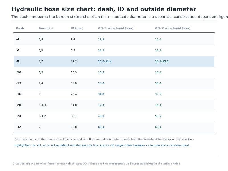
Figure 1. The full hydraulic hose size chart in one view: the dash number is the inside diameter in sixteenths of an inch, while outside diameter is a separate dimension that changes with hose construction and must be read from the datasheet.
Hydraulic Hose ID vs OD: Which Dimension Sizes the Hose?
The inside diameter sizes the hose; the outside diameter sizes the installation. The hydraulic hose ID vs OD distinction matters because the two dimensions answer different questions: one moves the fluid, the other decides whether the hose physically fits. Put the hydraulic hose ID vs OD distinction this way: if the number you hold was taken across the outside of the hose, you have a clearance measurement, not a size.
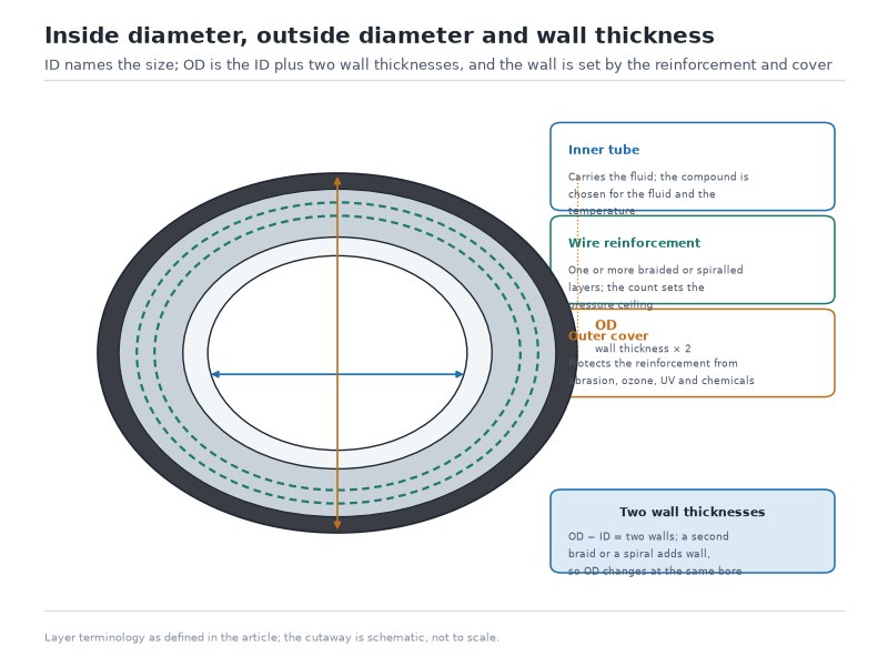
The five-dimension comparison near the top of this page sets dash size, ID, OD, bend radius and cut length side by side, with the consequence of getting each one wrong. The reason the two are so often confused is that ordinary consumer hose is sold by outside diameter — a garden hose or a water hose is measured across the outside because the wall is thin and the two dimensions are nearly the same. Hydraulic hose is not built that way. The reinforcement layers and the abrasion-resistant cover add a substantial wall, and how substantial depends entirely on how the hose is reinforced.
Why Identifying a Hose by Its OD Gives the Wrong Size
Measuring the outside diameter to work out what size a hose is will give you the wrong answer often enough to be a genuine hazard. A 1/2 inch bore hydraulic hose has a typical outside diameter of 20.0–21.4 mm in single-wire braid, 22.5–23.0 mm in two-wire braid and 23.8–25.4 mm in four-spiral construction — a spread of about 5 mm across constructions at one bore. Convert any of those to sixteenths and you land between dash -14 and dash -16 for a hose that is actually dash -8. The caliper reading is accurate; the method answers a different question.
The reliable way to establish the hydraulic hose dash size, in order of preference, is to read it off the layline printed on the hose cover, to look up the part number against the datasheet, or — only if the hose is unmarked — to cut a clean cross-section and measure the bore directly with calipers.
How to Measure Hydraulic Hose Size Correctly
Knowing how to measure hydraulic hose size properly takes about two minutes and only needs a caliper and a clean cut. Work in this order so that a worn or unreadable marking does not force you into a guess. This sequence is the whole of how to measure hydraulic hose size on a hose that has been in service, and it costs less time than a single re-ordered assembly.
- Read the layline first. The printed marking on the cover normally carries the dash size, the SAE or EN standard family, the working pressure and the date code, and how to read a hydraulic hose layline covers each of those fields in turn. If the layline is legible, you have the size without measuring anything.
- Check the part number against the datasheet. The layline identifies the size; the datasheet gives the published ID, OD and bend radius that the flow calculation should use.
- Cut a clean cross-section if the layline is gone. Use a hose cut-off saw or a fine-tooth blade so the reinforcement does not smear across the bore. A ragged cut will understate the bore, and on a two-wire hose a smeared cut can be off by more than a millimetre.
- Measure the bore across the widest point. Insert the caliper jaws inside the tube, square to the cut, and take the largest reading. Repeat at 90 degrees and use the larger figure — an oval cut or a slightly compressed hose reads small in one direction.
- Multiply the measured bore by 16 and round to the nearest whole number. A 0.500 inch bore gives 8.0, so the hose is -8. A 0.620 inch bore gives 9.9, so the hose is -10.
- Confirm with the fitting, not with the OD. If the hose is already crimped, the fitting insert size confirms the dash size. The outside diameter confirms nothing (Figure 2).
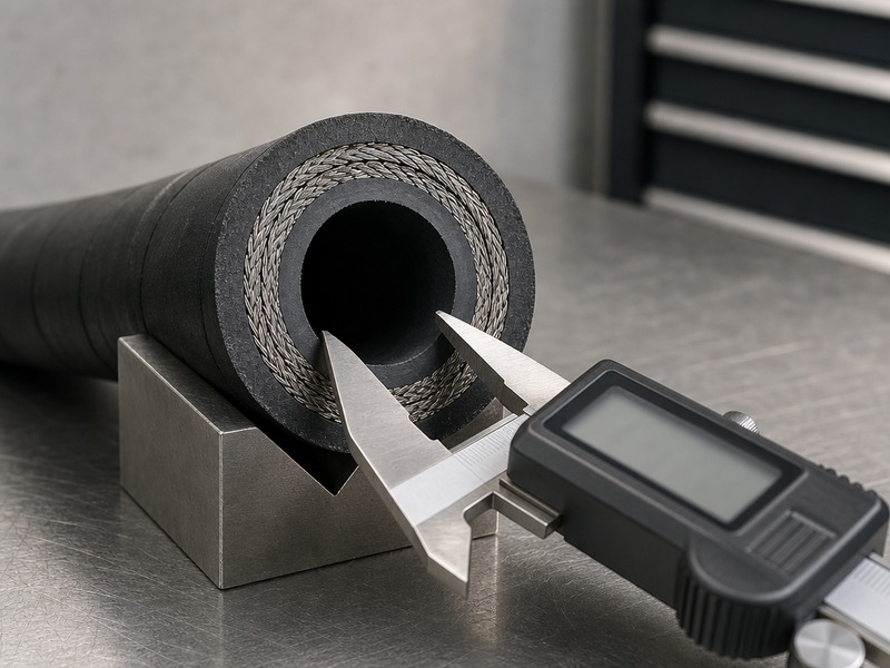
Figure 2. Measuring the bore on a clean cross-section is the only reliable field method when the layline is worn. The outside diameter is measured for routing checks, not for size identification.
Measuring ID Without Cutting the Hose
If the hose cannot be cut, the two remaining options are indirect and both need care. A bore gauge or a set of telescoping gauges inserted through the fitting end can be used on a straight, clean assembly, but the reading is only as good as the access. The more dependable indirect method is to measure the outside diameter and subtract twice the wall thickness, which you take from the datasheet. In practice, on a pressurised system, ordering a replacement from the layline or the part number is almost always faster and safer than reverse-engineering the size from measurements.
The Measurement Mistakes That Cause Wrong Orders
Three measurement errors recur in the field, and each has a characteristic consequence. Measuring the OD and converting to a dash size produces a hose two to four sizes too large, which will not fit the fittings. Measuring the bore on a cut made with a coarse blade reads undersized, which produces a hose one size too small.
The third error is subtler. Measuring an old, swollen hose — a hose that has absorbed fluid or been heat-aged — reads oversized at the bore and undersized in wall thickness at the same time, which is the strongest argument for using the part number rather than dimensions on a failed hose.
Dash Size Conversion: How Do You Convert Dash to Inch and Millimetre?
Dash size conversion is arithmetic, and because the arithmetic is fixed by the sixteenths rule, the same figures serve every manufacturer — every hydraulic hose dash size on a supplier’s list converts by exactly the same division, which is why a dash size conversion does not need a supplier-specific table. The consolidated chart above already pairs the dash number with its fractional inch, decimal inch, sixteenths and millimetre bore, so this section covers the conversions that come up in ordering, in drawing callouts, and in matching a metric port to an imperial hose: dash to inch, dash to millimetre, and a measured bore back to a dash number.
Converting in Your Head at the Counter
Two shortcuts cover nearly every conversion you will need without a calculator or a phone, and the consolidated chart above doubles as the hydraulic hose size chart PDF most workshops print and tape inside a cabinet door. To go from dash to millimetres, multiply the dash by 1.6 and accept that the answer is high by about 0.79 percent — a -12 hose is 19.2 mm by the shortcut against 19.05 mm exactly, a 0.15 mm gap. That is accurate enough to choose a fitting, and for a tolerance-critical drawing use the exact figure: dash × 1.5875. To go from a measured bore to a dash size, double the measurement twice to get sixteenths, or simply multiply by 16, which is the same operation.
The shortcut fails in one place worth knowing about: it does not convert dash size to fitting thread size. A -8 hose takes a -8 fitting insert, but the thread on the other end of that fitting has nothing to do with the number 8, and the next section covers that conversion separately because it is the one that actually causes wrong parts to arrive.
What Fitting Size Does a Hose Dash Size Take?
Hose dash size and fitting insert size are one-to-one — a -8 hose always takes a -8 fitting insert — but the thread that fitting presents to the port is a separate system entirely. This is the conversion that causes most wrong-part deliveries, because the dash number appears in the fitting product code and is then mistakenly read as a thread size.
Four different -8 fittings exist, all of which crimp onto the same -8 hose and none of which will screw into the same port — which is why a hydraulic hose fitting size chart has to be read as two separate charts, one for the hose side and one for the port side. A -8 JIC 37-degree flare male has a 3/4-16 thread. A -8 ORFS male has a 13/16-16 thread. A -8 NPTF male has 1/2 inch pipe threads at 14 threads per inch. A -8 SAE four-bolt flange has a 1-3/16 inch flange diameter with 1-1/2 inch bolt spacing in Code 61.
That is four incompatible connections behind one dash size, and it is why a hydraulic hose fitting size chart carries a separate column for each connection family rather than a single thread figure. The four -8 threads are the first row of the table below; every other dash size follows the same four columns. Keep the hydraulic hose dash size and the port thread on the same line of the quote, and a hose dash size chart becomes a nine-second lookup instead of a support ticket. The crimp tooling that finishes the assembly is then selected by hose dash size and fitting series rather than by thread, which is why a crimp die size chart is read off the dash size column.
Dash size to fitting thread chart — hose dash size with the corresponding thread for the four most common hydraulic connection families (SAE J514, SAE J1453, NPTF and SAE J518). “Not standard” means that connection family has no standard fitting at that dash size, so an adapter or a different family is required — it does not mean the dash size is unavailable.
| Hose dash size | JIC 37° flare (SAE J514) | ORFS (SAE J1453) | NPTF pipe | SAE flange, Code 61 bolt spacing |
|---|---|---|---|---|
| -4 | 7/16-20 | 9/16-18 | 1/4-18 | Not standard |
| -5 | 1/2-20 | Not standard | Not standard | Not standard |
| -6 | 9/16-18 | 11/16-16 | 3/8-18 | Not standard |
| -8 | 3/4-16 | 13/16-16 | 1/2-14 | 1-1/2 in, 1-3/16 in flange OD |
| -10 | 7/8-14 | 1-14 | Not standard | Not standard |
| -12 | 1-1/16-12 | 1-3/16-12 | 3/4-14 | 1-7/8 in, 1-1/2 in flange OD |
| -16 | 1-5/16-12 | 1-7/16-12 | 1-11-1/2 | 2-1/16 in, 1-3/4 in flange OD |
| -20 | 1-5/8-12 | 1-11/16-12 | 1-1/4-11-1/2 | 2-5/16 in, 2 in flange OD |
| -24 | 1-7/8-12 | 2-12 | 1-1/2-11-1/2 | 2-3/4 in, 2-3/8 in flange OD |
| -32 | 2-1/2-12 | Not standard | 2-11-1/2 | 3-1/16 in, 2-13/32 in flange OD |
Read the NPTF column carefully, because it hides its own trap. The dash size and the pipe size happen to coincide at -4, -6, -8, -12, -16, -20, -24 and -32 — a -8 hose takes 1/2 inch pipe thread, a -12 hose takes 3/4 inch pipe thread. That coincidence is a convenience, not a rule, and it stops being true wherever a dash size has no standard pipe equivalent. Threads are written as diameter–threads per inch, so 3/4-16 is a 3/4 inch thread at 16 threads per inch, and 1-11-1/2 is a 1 inch thread at 11-1/2 threads per inch.
The only dependable method is to identify the port thread first, then select the fitting, then confirm the fitting’s hose dash size. Read the hydraulic hose fitting size chart for the hose side and the port thread chart for the machine side, and match them in that order rather than trying to read both off one table.
When Hose Dash Size and Port Size Do Not Match
On many machines the port is deliberately smaller than the hose, and this is normal engineering rather than an error. A common excavator pattern is a -12 hose feeding a -8 port through an adapter, which keeps fluid velocity low in the long hose run while still matching the valve’s port. Two rules keep these assemblies reliable: keep any reduction to a single dash size at one adapter, because a sharper reduction concentrates flow and adds pressure drop exactly where the hose is already working hardest; and count the adapters on both ends before deciding the hose’s dash size, because a machine’s original hose may itself be the result of an adapter choice made years earlier.
Two further rules matter on any assembly where a reduction is unavoidable. Fit the adapter at the port rather than in the middle of the hose run, so the reduced-bore length is as short as possible. And if the machine needs a reduction of more than one dash size, that is usually a signal that the hose was oversized in the first place rather than that the port is too small.
Matching a hose to a port is one of the five decisions in a complete hose selection, alongside pressure, temperature, bend radius and fluid compatibility. If the sizing question is part of a wider selection, the sequence is worth following in full rather than solving size in isolation — the hydraulic oil hose selection guide walks through all five in order.
Hydraulic Hose Size Chart and Flow Capacity: Sizing by GPM
Flow capacity, not pressure, is what actually decides hose size on most circuits. A hose that is one dash size too small will still hold the system pressure, so nothing appears wrong at first — the oil simply moves too fast, and the energy lost to friction turns into heat that degrades the tube from the inside. Keeping fluid velocity inside the band used in fluid power line-sizing practice is the whole purpose of a flow-based sizing calculation.
The velocity limits below are the bands used in fluid power line-sizing practice, not a fixed standard requirement. Pressure lines are kept fastest because the runs are short and the heat has somewhere to go; return lines are run more slowly because they are usually longer; suction lines are run slowest of all because a pressure drop below atmospheric at the pump inlet causes cavitation, which damages the pump rather than the hose.
Velocity bands used in fluid power line-sizing practice, by line function
| Line function | Velocity band (ft/s) | Metric equivalent | Consequence of exceeding it |
|---|---|---|---|
| Pressure line (pump to actuator) | 15–20 ft/s | 4.6–6.1 m/s | Pressure drop, turbulence, oil heating, tube erosion |
| Return line (actuator to reservoir) | 10–15 ft/s | 3.0–4.6 m/s | Back pressure, sluggish operation, heat build-up |
| Suction line (reservoir to pump) | 2–4 ft/s | 0.6–1.2 m/s | Cavitation, pump damage, noise and vibration |
Two formulas link flow, velocity and bore, and they are the only equations you need for hose sizing. In imperial units, velocity in feet per second equals 0.3208 times the flow in gallons per minute divided by the cross-sectional area of the bore in square inches. In metric units, velocity in metres per second equals 21.22 times the flow in litres per minute divided by the square of the bore in millimetres. In symbols: v (ft/s) = 0.3208 × Q (gpm) ÷ A (in²), where A is the bore area in square inches, and v (m/s) = 21.22 × Q (l/min) ÷ d² (mm), where d is the bore in millimetres. The two constants used on this page and in our sizing guide are the same relation written two ways: 0.3208 × 4 ÷ π = 0.4085, and 1 ÷ 2.448 = 0.4085. Rearranged, that gives Q (gpm) = 2.448 × v (ft/s) × d² (in), equivalently d² (in²) = Q (gpm) ÷ (2.448 × v (ft/s)), and v (ft/s) = 0.408 × Q (gpm) ÷ d² (in). The three constants used across these guides — 0.408, 2.448 and 3.117 — are three writings of one relation and differ by less than 0.2 percent, purely because of how the units are converted.
Rearranged to solve for the bore instead of the velocity, the imperial form is minimum ID (in) = √( Q (gpm) ÷ (2.448 × v (ft/s)) ), and the metric form is minimum ID (mm) = √( 21.22 × Q (l/min) ÷ v (m/s) ). Both give the minimum bore for the velocity you chose; round up to the next standard dash size. The velocity bands, the worked examples and the pressure-drop check behind these limits are set out in our how to size a hydraulic hose from flow rate guide.
Maximum flow rate by dash size at the velocity limits used in fluid power line-sizing practice, for pressure, return and suction lines (computed with 2.448 — that is, 1 ÷ 0.4085 — from the nominal bore)
| Dash size | ID (inch) | Pressure line at 20 ft/s | Return line at 10 ft/s | Suction line at 4 ft/s |
|---|---|---|---|---|
| -4 | 0.250 | 3.1 GPM (11.6 L/min) | 1.5 GPM (5.8 L/min) | 0.6 GPM (2.3 L/min) |
| -5 | 0.313 | 4.8 GPM (18.1 L/min) | 2.4 GPM (9.1 L/min) | 1.0 GPM (3.6 L/min) |
| -6 | 0.375 | 6.9 GPM (26.1 L/min) | 3.4 GPM (13.0 L/min) | 1.4 GPM (5.2 L/min) |
| -8 | 0.500 | 12.2 GPM (46.3 L/min) | 6.1 GPM (23.2 L/min) | 2.4 GPM (9.3 L/min) |
| -10 | 0.625 | 19.1 GPM (72.4 L/min) | 9.6 GPM (36.2 L/min) | 3.8 GPM (14.5 L/min) |
| -12 | 0.750 | 27.5 GPM (104.3 L/min) | 13.8 GPM (52.1 L/min) | 5.5 GPM (20.9 L/min) |
| -16 | 1.000 | 49.0 GPM (185.4 L/min) | 24.5 GPM (92.7 L/min) | 9.8 GPM (37.1 L/min) |
| -20 | 1.250 | 76.5 GPM (289.6 L/min) | 38.3 GPM (144.8 L/min) | 15.3 GPM (57.9 L/min) |
| -24 | 1.500 | 110.2 GPM (417.0 L/min) | 55.1 GPM (208.5 L/min) | 22.0 GPM (83.4 L/min) |
| -32 | 2.000 | 195.9 GPM (741.4 L/min) | 97.9 GPM (370.7 L/min) | 39.2 GPM (148.3 L/min) |
For runs longer than a few metres, or where the fluid sits outside the ISO VG 32–68 band at working temperature, size on 20 to 30 percent less than the table figure. That reduction is a line-sizing practice rather than a fixed standard requirement, and it is expressed against the flow figure in the table.
Worked Example: Sizing a 20 GPM Pressure Line
A system moves 20 GPM at 3,000 PSI in the main pressure line and the target velocity is 20 ft/s. Applying the imperial formula, the minimum bore is the square root of 20 divided by the product of 2.448 and 20, which is the square root of 0.408 — 0.639 inch. Multiplying by 16 gives a required dash size of 10.2, and because you always round up, the answer is dash -12. The -10 hose would have given a velocity of 20.9 ft/s (20.89–20.91 depending on whether the constant is rounded to 0.408 or carried at 0.4085) — close, but above the limit you set, and on a long run the accumulated pressure drop would be the penalty.
Worked Example: Sizing a Return Line and a Suction Line
The same 20 GPM through a return line at a 10 ft/s target needs a minimum bore of the square root of 20 divided by 24.48, which is 0.904 inch, or dash 14.5 — so the correct size is dash -16. Through a suction line at a 4 ft/s target, the same flow needs the square root of 20 divided by 9.792, which is 1.429 inch, or dash 22.9 — so the correct size is dash -24. Identical flow, three different correct answers, because the velocity limit changed with the line function. That is why the line function is decided before the size is calculated.
In metric terms the arithmetic is quicker to do by hand. A 60 L/min suction line at a 1.2 m/s limit needs a bore of the square root of 21.22 times 60 divided by 1.2, which is 32.6 mm — dash 20.5, so dash -24. A 100 L/min pressure line at a 5 m/s limit needs the square root of 21.22 times 100 divided by 5, which is 20.6 mm — dash 13.0, so dash -14; because -14 is an order-in size in most ranges, the practical stocked answer is dash -16.
Why Oversizing Is Also a Mistake
Undersizing a hose is the dangerous error, but oversizing is a costing and installation error that is worth avoiding rather than ignoring. A hose two dash sizes larger than required costs more per metre, weighs more, has a larger outside diameter that may not fit existing clamps and sleeves, and bends to a larger minimum radius that may not fit the routing. On a suction line, modest oversizing is normal practice. On a pressure line, sizing to the velocity limit and stopping there is the correct choice.
Metric Hydraulic Hose Size Chart: How Do DN and Dash Size Compare?
Metric hydraulic hose is sized by DN, which stands for *diamètre nominal* — nominal diameter — and it is where the metric and imperial systems stop agreeing. The two systems describe the same hose families, and at most sizes the DN number and the SAE dash number map cleanly, but not always by the arithmetic you would expect.
DN to dash size conversion chart for braided hydraulic hose, with the nominal bore each system specifies (EN 853 2SN compared with SAE 100R2)
| EN / DN size | Nominal bore (mm) | SAE dash size | Nominal bore (mm) | Do they match exactly? |
|---|---|---|---|---|
| DN6 | 6.3 | -4 | 6.4 | Within 0.1 mm |
| DN8 | 8.0 | -5 | 7.9 | Within 0.1 mm |
| DN10 | 9.5 | -6 | 9.5 | Yes — DN10 is a 3/8 in hose |
| DN12 | 12.5 | -8 | 12.7 | Within 0.2 mm |
| DN16 | 16.0 | -10 | 15.9 | Within 0.1 mm |
| DN19 | 19.0 | -12 | 19.0 | Yes |
| DN25 | 25.4 | -16 | 25.4 | Yes |
| DN31 | 31.8 | -20 | 31.8 | Yes |
| DN38 | 38.1 | -24 | 38.1 | Yes |
| DN51 | 50.8 | -32 | 50.8 | Yes |
Metric Sizes in Practice: DN, Millimetre and the UK Supply Chain
Most of the world’s hose catalogues are written in DN, and in the UK and much of Europe a hydraulic hose is normally ordered by DN and the EN standard family rather than by dash number. A UK supplier’s “DN12 2SN hose” and an American “-8 100R2 hose” describe the same 1/2 inch bore, and the fittings are interchangeable as long as both sides are named by their thread rather than their dash number.
How Is the -20 Size Written in Other Catalogues?
The -20 bore is written DN31 here, and some catalogues print the same size as DN32 — the two labels describe one nominal bore (31.5–31.8 mm depending on the standard table), so compare millimetre figures rather than label numbers when you order.
The DN10 Trap
DN10 is not a dash -10 hose: DN10 is a 9.5 mm bore, which is 3/8 inch, or dash -6, and dash -10 is a 5/8 inch bore written DN16. It reads like a 10 mm bore and it is tempting to equate it with the dash size that shares its number, but the two numbering systems collide on similar-looking numbers that mean completely different bores. Ordering a DN10 hose and expecting a -10 fitting produces an assembly that will not go together, and the same trap exists in the other direction. Convert through the millimetre bore and never through the number itself: every metric dash size conversion in this guide is built on that one rule.
A second, subtler point is worth knowing when you are comparing supplier datasheets. The EN 853 2SN and SAE 100R2 specifications describe the same two-wire-braid construction, but their published tables do not always agree on the pressure rating for a given nominal bore — the metric standard’s rating for one size can be higher than the SAE figure, or lower, depending on which size you are reading.
This is not a manufacturer error; it is two standards drawing their rating tables differently, and the SAE, ISO and DIN hydraulic hose standards comparison sets out where each framework draws its boundaries. The consequence for a buyer is simple: state the standard you want on the purchase order, and check the datasheet figure for the specific size rather than assuming the rating carries across the entire size range.
Which System Goes on the Purchase Order
Write the order the way your supplier’s catalogue is built, and write both systems if there is any chance of ambiguity — a hose dash size chart is a conversion aid, never a substitute for naming the standard you want. A line such as “SAE 100R2AT, dash -8 (1/2 in, DN12), 3,500 psi minimum working pressure” removes every interpretation, because 3,500 psi is the published 100R2 figure for a -8 bore and a 4,000 psi line would describe a -6 hose.
If you are buying to an EN specification, give the DN size, the standard number and the working pressure; if you are buying to an SAE specification, give the dash size, the 100R family and the working pressure. Blanket descriptions such as “1/2 inch hydraulic hose” are the ones that come back wrong, because a supplier has to guess whether you meant bore, outside diameter or pipe size.
Does Hose OD Change With Construction? Yes — Here Is the Table
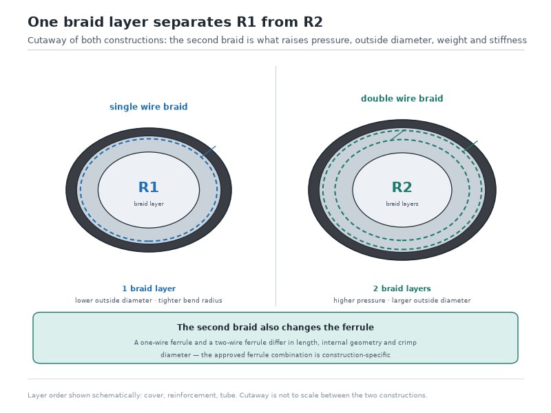
Hose outside diameter changes with construction at the same dash size, and the reason is arithmetic rather than manufacturing variation. Each reinforcement layer adds wire or fibre thickness plus the cover extruded over it, and because the inside diameter is fixed by the dash size, every extra layer pushes the outside diameter outward while the bore stays the same.
Typical outside diameter by dash size and hose construction (representative values for standard braided and spiral hoses; OD varies by manufacturer and cover compound, so confirm the datasheet before finalising routing. These are representative published values, not a standard table.)
| Dash size | ID (mm) | OD, 1-wire braid (mm / in) | OD, 2-wire braid (mm / in) | OD, 4-spiral (mm / in) | Wall added, 1-wire to 4-spiral |
|---|---|---|---|---|---|
| -4 | 6.4 | 13.5 / 0.53 | 15.0 / 0.59 | Not standard | — |
| -6 | 9.5 | 16.5 / 0.65 | 18.5 / 0.73 | 20.0 / 0.79 | +3.5 mm |
| -8 | 12.7 | 20.0–21.4 / 0.79–0.84 | 22.5–23.0 / 0.89–0.91 | 23.8–25.4 / 0.94–1.00 | ≈5 mm |
| -10 | 15.9 | 23.5 / 0.93 | 26.0 / 1.02 | 28.0 / 1.10 | +4.5 mm |
| -12 | 19.0 | 27.0 / 1.06 | 30.0 / 1.18 | 32.5 / 1.28 | +5.5 mm |
| -16 | 25.4 | 34.0 / 1.34 | 37.5 / 1.48 | 41.0 / 1.61 | +7.0 mm |
| -20 | 31.8 | 42.0 / 1.65 | 46.0 / 1.81 | 50.0 / 1.97 | +8.0 mm |
| -24 | 38.1 | 49.0 / 1.93 | 53.5 / 2.11 | 58.0 / 2.28 | +9.0 mm |
| -32 | 50.8 | 63.0 / 2.48 | 69.0 / 2.72 | 74.0 / 2.91 | +11.0 mm |
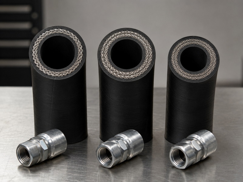
The practical reading of this table is that a construction change is also a routing change. Moving a -12 line from two-wire braid to four-spiral to gain pressure capacity increases the outside diameter by about 2.5 mm, which is enough to stop the hose passing through an existing protective sleeve or a bulkhead grommet sized for the braided hose. When a machine is being upgraded for higher pressure, check the clearance as well as the rating (Figure 3).
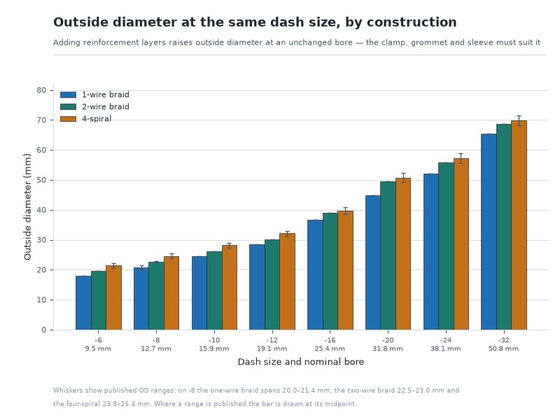
Figure 3. At the same dash size, one-wire braid, two-wire braid and four-spiral hose have progressively larger outside diameters. OD is a routing dimension and must be read from the datasheet, never inferred from the dash size.
How Does Working Pressure Change With Dash Size?
Working pressure falls as the bore rises within the same construction, which is the opposite of what most people expect and one of the reasons a hose size chart should always be read alongside a pressure rating chart. The reason is wall strength relative to bore: a smaller bore concentrates the same reinforcement over a smaller area and holds more pressure, while a larger bore gives the reinforcement more area to contain with proportionally the same wire.
EN 853 2SN working pressure and minimum burst pressure by dash size (the standard specifies a minimum burst pressure of four times the maximum working pressure; ratings are published values and must be confirmed against the manufacturer’s datasheet for the exact construction and size)
| Dash size | ID | Working pressure (EN 853 2SN, PSI) | Working pressure (EN 853 2SN, bar) | Minimum burst pressure, 4 × WP (PSI) | Typical use at this size |
|---|---|---|---|---|---|
| -4 | 1/4 in | 5,800 | 400 | 23,200 | Pilot and case drain lines |
| -6 | 3/8 in | 4,000 | 275 | 16,000 | General mobile pressure lines |
| -8 | 1/2 in | 3,500 | 240 | 14,000 | General mobile and industrial pressure lines |
| -10 | 5/8 in | 3,000 | 207 | 12,000 | Medium-flow supply lines |
| -12 | 3/4 in | 2,750 | 190 | 11,000 | Main supply and steering lines |
| -16 | 1 in | 2,250 | 155 | 9,000 | High-flow return and supply lines |
| -20 | 1-1/4 in | 1,625 | 112 | 6,500 | Large flow circuits |
| -24 | 1-1/2 in | 1,500 | 103 | 6,000 | Heavy equipment return lines |
| -32 | 2 in | 1,250 | 86 | 5,000 | High-volume industrial hydraulics |
SAE J517 100R2AT is the SAE equivalent family, and the two standards publish different working pressures for the same dash size — this table follows EN 853 2SN. Confirm the figure for the exact dash size and standard on the datasheet before ordering.
Three consequences follow, and each of them is a sizing decision rather than a hose specification. First, if a system needs both high flow and high pressure, the dash size that solves the flow will not solve the pressure in a two-wire braid hose, and the answer is a higher construction family rather than a smaller hose. Second, changing the dash size changes the pressure rating, so a “same hose, bigger size” substitution is never a like-for-like swap.
Third, a hose that is the same dash size and a higher construction family has a different pressure rating again, so the rating must be read from the row that matches both the dash size and the family. The complete family-by-family rating tables are set out in the SAE 100R hydraulic hose standards guide.
Why Working Pressure Is Not the Whole Pressure Story
The working pressure printed on the hose is a steady-state figure, and the pressure the reinforcement actually sees is the working pressure plus every pressure spike and every impulse cycle the circuit produces. Impulse life is tested by cycling the assembly at a percentage of its working pressure — 133 percent in the SAE 100R2 and EN ISO 6803 test procedures — for hundreds of thousands of cycles, and a construction that passes easily at one dash size may not pass at another. When a line runs on a machine with frequent load reversals, matching the pressure rating to the system pressure is the minimum requirement, not the whole of it.
Which Dimensions Besides Bore Decide Whether a Hose Fits?
Size in hydraulic hose means bore, but three other published dimensions decide whether an assembly can be installed at all. Bend radius governs whether the hose can be routed around the obstruction in front of you without kinking. Weight per metre governs whether the assembly needs support over a long run. Cut length and assembly length govern whether the finished hose reaches across the gap it was ordered for. How those dimensions are defined and measured on a hose already in service is covered in our how hydraulic hose sizes are measured guide.
Typical minimum bend radius and weight for representative sizes and constructions — the two published dimensions checked from a table; cut length is a measurement, and the method is set out below
| Construção | Dash size | ID (mm) | OD (mm) | Min. bend radius | Peso |
|---|---|---|---|---|---|
| SAE 100R1 (1-wire braid) | -4 | 6.4 | 13.5 | 100 mm / 3.9 in | 0.23 kg/m (0.15 lb/ft) |
| SAE 100R1 (1-wire braid) | -8 | 12.7 | 20.0–21.4 | 130 mm / 5.1 in | 0.42 kg/m (0.28 lb/ft) |
| SAE 100R1 (1-wire braid) | -12 | 19.0 | 27.0 | 240 mm / 9.4 in | 0.72 kg/m (0.48 lb/ft) |
| SAE 100R2 (2-wire braid) | -4 | 6.4 | 15.0 | 100 mm / 3.9 in | 0.33 kg/m (0.22 lb/ft) |
| SAE 100R2 (2-wire braid) | -8 | 12.7 | 22.5–23.0 | 180 mm / 7.1 in | 0.62 kg/m (0.42 lb/ft) |
| SAE 100R2 (2-wire braid) | -12 | 19.0 | 30.0 | 265 mm / 10.4 in | 1.05 kg/m (0.71 lb/ft) |
| SAE 100R16 (compact 2-wire) | -8 | 12.7 | 20.0 | 115 mm / 4.5 in | 0.52 kg/m (0.35 lb/ft) |
| SAE 100R12 (4-spiral) | -8 | 12.7 | 23.8–25.4 | 130 mm / 5.1 in | 0.78 kg/m (0.52 lb/ft) |
| SAE 100R12 (4-spiral) | -12 | 19.0 | 32.5 | 240 mm / 9.4 in | 1.25 kg/m (0.84 lb/ft) |
| SAE 100R12 (4-spiral) | -16 | 25.4 | 41.0 | 300 mm / 11.8 in | 1.85 kg/m (1.24 lb/ft) |
| SAE 100R13 (6-spiral) | -16 | 25.4 | 44.0 | 330 mm / 13.0 in | 2.20 kg/m (1.48 lb/ft) |
Rows are named by construction family and its standard: 100R1 = EN 853 1SN, 100R2 = EN 853 2SN / SAE J517 100R2AT, 100R16 = EN 857 2SC, 100R12 and 100R13 = SAE J517 / EN 856. These are representative published values, not a standard table; confirm the datasheet for the exact construction and size.
The comparison worth noticing is the -8 row across three constructions. A compact two-wire hose such as SAE 100R16 delivers the same pressure class as a standard two-wire hose in the same dash size, but with an outside diameter of 20.0 mm against 22.5–23.0 mm and a 115 mm bend radius against 180 mm. Where routing space is the binding constraint, that difference in outside diameter and bend radius is often more useful than another few hundred PSI of headroom.
Measuring Length Correctly
Cut length is measured along the centreline of the finished assembly, from the sealing face of one end fitting to the sealing face of the other. It is not in the dimension table above because it is a measurement rather than a published value — the two published dimensions that table carries are bend radius and weight. Read the length from the ends of the fittings and the answer will be wrong: the fitting’s own length does not change, but its orientation does. On an assembly with a 90-degree fitting at one end, the centreline measurement is what a replacement must match, because the fitting’s own length does not change but its orientation does. When ordering, give the length in millimetres or inches together with the fitting orientation at each end, and mark which end is which.
An excavator boom line that is 50 mm short will not reach once the machine is at full extension, and re-routing to gain 50 mm usually means a tighter bend than the minimum radius allows — which is how a correctly sized hose still ends up failing early.
What Are the Most Common Hydraulic Hose Size Mistakes?
Six sizing errors account for most returned hydraulic hose assemblies: identifying a hose by its outside diameter, rounding a flow calculation down instead of up, assuming one dash size carries one pressure rating, ordering by DN number instead of millimetre bore, reusing the old hose as the length reference, and ignoring the outside diameter change when the construction is upgraded. Each one has a recognisable signature, which makes this list a diagnostic tool as well as a checklist.
- Sizing by outside diameter instead of dash size. The resulting hose is two to four dash sizes too large and will not accept the fittings. Cost: a returned assembly and a lost production window.
- Rounding a flow calculation down instead of up. A 20.9 ft/s result rounded to the nearest size instead of the next size up runs the oil hot. Cost: shortened hose life and premature tube degradation, often blamed on the hose supplier.
- Assuming the same dash size means the same pressure rating. A -12 hose in one construction family is not a substitute for a -12 hose in another. Cost: a burst failure under a pressure the original hose was rated for.
- Ordering by DN number instead of millimetre bore. The DN10-to-dash-size trap produces a hose one size away from what was intended. Cost: fittings that will not mate, discovered at installation.
- Reusing the old hose as the length reference without checking the routing. Old hose relaxes, stretches and is sometimes itself a replacement. Cost: an assembly that fits loosely or pulls tight.
- Ignoring the outside diameter change when upgrading construction. A pressure upgrade that adds 2.5 mm of OD may not fit the existing sleeve or grommet. Cost: re-routing under time pressure, or the wrong bend radius being accepted.
The common thread is that every one of these errors is a conversion error rather than a product error — a hose that was correct for the specification that was sent. When a correctly specified hose still fails early, the cause is usually mechanical rather than dimensional, and the failure pattern itself identifies it. Understanding the failure mechanisms is a separate diagnostic exercise from understanding the size chart, and the two are often confused when a hose fails in service; the hydraulic hose failure causes guide covers that side of the problem in detail — see Figure 4 for the measurement that causes the most expensive of these errors.
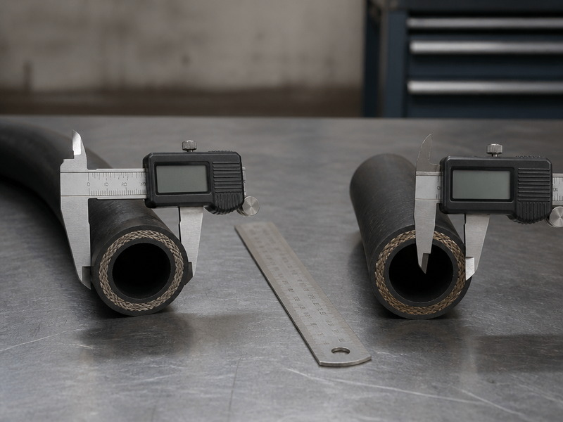
Figure 4. The most expensive sizing error is also the most common: measuring the outside diameter, converting it to a dash size, and ordering a hose that is several sizes too large for its fittings.
Frequently Asked Questions
What does the dash number mean on a hydraulic hose?
The dash number is the hose inside diameter expressed in sixteenths of an inch, so a -8 hydraulic hose has an 8/16 inch bore, or 1/2 inch, and 12.7 mm. It is simultaneously the size you order the hose in, the fitting insert size that crimps onto it, and — for a two-wire braid hose — the reference you need before you look at a working pressure table, because the rating moves with both the dash size and the construction family.
Is hydraulic hose measured by ID or OD?
The hydraulic hose ID vs OD question is settled by purpose: the inside diameter carries the fluid and sets the dash size, and the outside diameter decides only what the hose fits through. Hydraulic hose is measured and ordered by inside diameter, and treating the outside diameter as the size is the error that shows up as a returned assembly: at a -8 bore the outside diameter of a standard two-wire hose sits at 22.5–23.0 mm, which converts to somewhere between dash -14 and dash -16, so an OD-based order arrives two to four sizes too large to accept its fittings. Measure the bore, and use the outside diameter only to check clearance.
What is a -8 hydraulic hose in millimetres?
A -8 hydraulic hose has a 1/2 inch bore, which is 12.7 mm nominal. The nearest metric label is DN12, whose nominal bore is 12.5 mm, so the two systems differ by 0.2 mm at this size. That gap does not matter when you order hose, but it does matter if you are matching a metric port with a hard tolerance: go by the published bore range on the datasheet rather than by either label.
Is DN10 the same as dash -10?
The two numbers describe different bores, and the collision of names is the single most common metric-imperial mistake. DN10 has a 9.5 mm bore and is therefore a 3/8 inch hose, which is dash -6. Dash -10 is a 5/8 inch bore, written DN16 in the metric system. Convert through the millimetre figure in both directions and the label numbers stop being dangerous.
Why does the same dash size have different outside diameters?
Because each reinforcement layer and its cover add wall thickness over a bore that is fixed by the dash size. At a -8 bore, single-wire braid runs 20.0–21.4 mm outside, two-wire braid 22.5–23.0 mm and four-spiral 23.8–25.4 mm — about 5 mm of spread at one bore. Read the OD for the exact construction from the datasheet before finalising a sleeve, grommet or bulkhead clearance.
How do I identify a hydraulic hose with no markings?
Knowing how to measure hydraulic hose size on an unmarked hose comes down to one dimension. Cut a clean cross-section with a fine-tooth blade or a hose saw, measure the bore across its widest point with calipers, then multiply by 16 and round to the nearest whole number: a 0.500 inch bore gives dash -8. Take a second reading at 90 degrees and use the larger figure, because a slightly oval cut reads small in one direction. If the hose is already crimped, the fitting insert size confirms the dash size in a few seconds.
Does a bigger hydraulic hose have a higher pressure rating?
For the same construction, a larger bore carries a lower working pressure, because the same reinforcement has more area to contain. In EN 853 2SN, a two-wire braid hose is rated 4,000 PSI at a 3/8 inch bore, 3,500 PSI at 1/2 inch, 2,750 PSI at 3/4 inch and 2,250 PSI at 1 inch; SAE J517 100R2AT publishes different figures for the same sizes, so name the standard on the order. Where a system needs high flow and high pressure together, the answer is a higher construction family such as four-spiral, not a different dash size.
What size hydraulic hose do I need for 20 GPM?
Decide the line function first, then apply that function’s velocity limit. At 20 ft/s for a pressure line, 20 GPM needs a minimum bore of 0.639 inch, which rounds up to dash -12. The same flow at 10 ft/s for a return line needs 0.904 inch, so dash -16, and at 4 ft/s for a suction line it needs 1.429 inch, so dash -24. Identical flow, three different correct answers. Two ways of reading the same numbers: the flow capacity table above gives the flow each size carries at the limit (a -10 carries 19.1 GPM at 20 ft/s), while this answer starts from the flow you have and returns the minimum bore; the table is for checking a size you already have, the formula is for choosing one.
Are the most common hydraulic hose sizes the same across industries?
The five sizes that cover most mobile and industrial hydraulic work are -6 (3/8 in), -8 (1/2 in), -10 (5/8 in), -12 (3/4 in) and -16 (1 in), and that set holds across construction families and across both the SAE and EN catalogues. Below -6 the sizes serve pilot, control and lubrication lines; above -16 they serve high-flow supply, return and suction circuits on heavy equipment.
Can a hydraulic hose be used for air or water?
A hydraulic hose can physically carry air or water, and doing so safely depends on a rating written for that service rather than on the hydraulic rating. Gas service stores energy and permits permeation through the tube, neither of which a hydraulic working pressure figure addresses, so a compressed-air requirement belongs with an air hose. The hydraulic hose versus air hose comparison sets out where the two specifications diverge.
How much clearance does a hydraulic hose need for routing?
Clearance is driven by two published figures, not by the bore: the outside diameter for the space the hose occupies, and the minimum bend radius for the curve it has to take. Add the OD to the diameter of any grommet or sleeve it passes through, subtract nothing for the hose swelling under pressure, and remember that a construction upgrade at the same dash size can add a few millimetres of OD. Where the routing is tight, a compact braid family buys back both OD and bend radius at the same pressure class.
What tolerance does a hydraulic hose bore carry?
The published bore is a range, not a single figure. An EN 853 1SN -8 hose, for example, is published with an inside diameter of 12.3–13.5 mm, and a 100R2 -8 hose with a comparable band around 12.7 mm nominal. The tolerance matters whenever a flow calculation lands close to a velocity limit: use the published minimum ID for the exact construction rather than the nominal dash figure, and the velocity you calculate will be the worst case rather than the average.
Quick Reference: What to Send a Supplier With Your Size
A quote request that contains the following seven items can be priced and built without a single follow-up question. Leaving any one of them out is what turns a two-day quotation into a two-week exchange. Send those seven items and the matching end connection comes back confirmed: request a quote and free samples.
Minimum information by reader for a size-chart enquiry, and what the HENGHUA reply answers
| You are… | Send at minimum | You get back |
|---|---|---|
| Selecting for a new build | flow rate, line function, working pressure | dash size, construction, fitting thread |
| Replacing an assembly on site | layline or dash size, port end, centreline length | an interchangeable assembly with the same ends |
| Exporting to an EN or metric market | DN size, standard family, quantity, documentation | the equivalent dash size and the standard named on the quote |
- Dash size, with the inch and millimetre bore for confirmation — for example, dash -12 (3/4 in, 19.0 mm).
- Construction and standard family — for example, SAE 100R2AT, EN 853 2SN, or SAE 100R12.
- Working pressure and the fluid — system pressure in PSI or bar, and the fluid type, including any water-glycol, biodegradable ester or phosphate ester specification.
- Temperature range — both the continuous operating temperature and any short-duration peaks.
- Cut length, assembly length and routing constraints — cut length and assembly length measured along the centreline, plus the minimum bend radius available and whether the hose passes through a sleeve, grommet or bulkhead.
- Fitting type and thread at each end — for example, JIC 37-degree male at one end and ORFS female at the other. A hydraulic hose fitting size chart covering the JIC, ORFS, NPTF and flange families is the reference to quote from here.
- Quantity and the application context — OEM programme, distribution stock, or fleet replacement, since the three carry different documentation and packaging expectations.
HENGHUA: Hydraulic Hose Made to the Dash Size You Specify
HENGHUA manufactures hydraulic hose and finished hose assemblies across the constructions this chart covers — SAE 100R1 and 100R2 wire braid from -4 to -32, compact 100R16 and 100R17, four- and six-spiral 100R12, 100R13 and 100R15, textile-braided 100R3 and 100R6, thermoplastic 100R7 and 100R8, and PTFE 100R14 — with crimped JIC, ORFS, NPT, BSP and SAE flange ends available in every dash size listed in the tables above.
Because we compound the tube and cover, braid the wire reinforcement, extrude the hose, crimp the assemblies and impulse-test finished lines in our own plant, every assembly leaves with a test record that identifies the dash size, the construction, the fitting thread and the proof pressure it was tested to. That traceability is the direct answer to the sizing problem this guide describes: when the specification on the purchase order includes the dash size, the standard family and the fitting thread, the assembly that arrives can be checked against all three in a few minutes rather than discovered to be wrong at installation.
In practice the requests our engineering team handles most are the ones where the size and the pressure requirement conflict — a machine needs more flow in a tight routing envelope, or a pressure upgrade that will not fit the existing sleeve. Those are solvable by changing construction or by moving to a compact braid rather than by changing the dash size, and they are worth a conversation before the order is placed rather than after.
Send us the seven-point list above and our engineers will confirm the correct dash size, construction and fitting thread, and quote with lead time and free samples for qualification. Request a quote and free samples.
Final Verdict: Read the Dash Size, Then Check the OD
A hydraulic hose size chart is a conversion tool, and the conversion it performs most usefully is from a dash number to a bore you can actually calculate with. Read the dash size to order the hose and the fitting; convert it to inches or millimetres to size the line for flow; and check the outside diameter and bend radius from the datasheet to confirm the hose will route where it has to go. Those three steps, in that order, resolve almost every sizing question that reaches a workshop, because they separate the two different jobs a hose size chart performs — specifying the product and validating the installation.
Two figures are worth carrying away from this guide. The first is that a dash number divided by sixteen is the bore in inches, and multiplied by 1.5875 is the bore in millimetres. The second is that DN10 is a 9.5 mm bore — a 3/8 inch hose — and not a dash -10 hose, which is where a surprising proportion of metric-and-imperial mix-ups begin. Everything else in the tables above is a lookup once those two are fixed. If the dash size is settled and the port thread is the open question, send the port end and the dash size and we will confirm the matching end connection: request a quote and free samples.
 English
  Spanish
  Portuguese
  French
  German
  Arabic
  Russian