
Why This Weld Fitting Hydraulic Adapter 1CW/1DW Passes the Compliance Gate
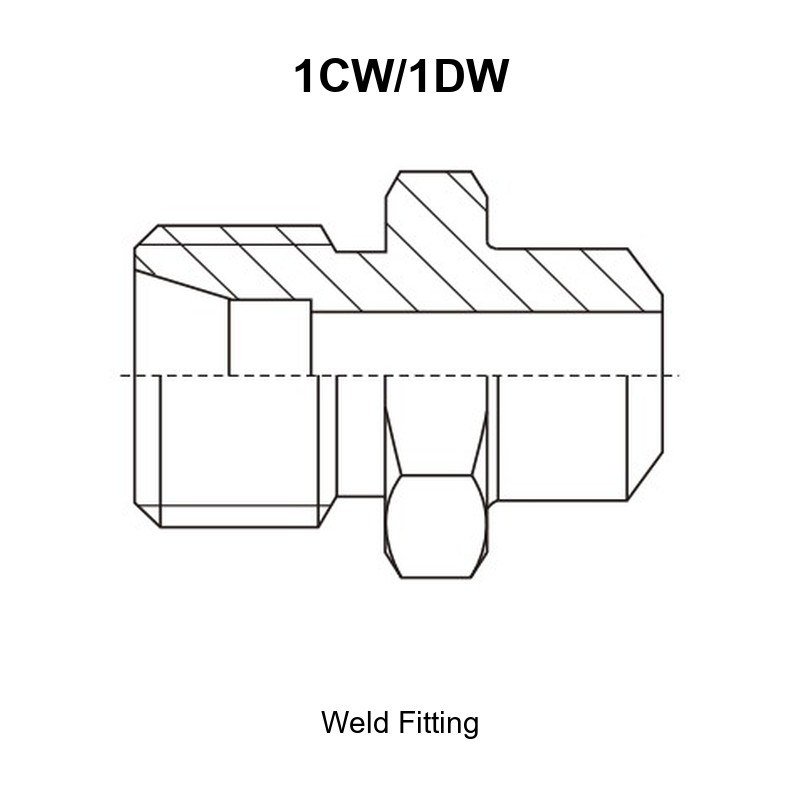
The weld fitting hydraulic adapter 1CW/1DW is a straight steel adapter with a metric male stud end on one side and a weld-on tube end on the other. The stud end takes a metric tube nut in the DIN 2353 / ISO 8434-1 light series L or heavy series S system, and the opposite end is welded directly to the pipe run, so a leak path is removed instead of added.
- Stud end: metric male thread, M12X1.5 to M52X2, matched row by row to a tube outside diameter.
- Weld end: tube outside diameter 6 mm to 42 mm with a weld boss diameter D and weld insertion depth B taken from the drawing.
- Pressure groups from the drawing: 31.5 MPa and 16 MPa (light series L), 63 MPa, 40 MPa and 31.5 MPa (heavy series S).
Ventajas principales
- One welded joint instead of two threaded joints: the weld fitting hydraulic adapter 1CW/1DW replaces a threaded nipple plus a hose tail at the pipe end, which is the usual way to remove a chronic weep point on a tube run.
- Documented weld geometry: the drawing states the weld boss diameter D and the insertion depth B for every row, so the welder works to a number rather than to a judgement call.
- Light and heavy series in one matrix: 22 catalogue rows cover light series L from 6 mm to 42 mm tube and heavy series S from 6 mm to 38 mm tube.
- Matched to the tube system you already use: the stud end follows DIN 2353 / ISO 8434-1 metric tube practice, so no hybrid hose end or adapter stack is needed on the tube side.
- RN option for a ready tube connection: the RN version is supplied complete with cutting ring and nut, so the tube joint is assembled on site without sourcing separate ring and nut parts.
- Batch traceability: mill test reports, dimensional inspection reports and pressure test records are available per production batch on request.
Especificaciones técnicas
What Is a Weld Fitting Hydraulic Adapter?
It is a one-piece machined steel adapter whose first end is a metric male stud thread for a tube nut and whose second end is a plain weld neck. The weld neck is fused to the tube or pipe, so the joint is permanent and needs no ferrule, cone or seal.
This is not a butt weld tube adapter for a tube-to-tube joint, and it is not a stud end for an O-ring boss port. The weld end must be welded; it cannot be assembled with a nut, and it must not be confused with a weld-on nipple that carries its own sealing seat.
Connection 1: Metric Male Stud End (E)
| Attribute | Detalle |
|---|---|
| End type | Metric male thread for a tube nut, straight |
| Thread range | M12X1.5 to M52X2 |
| Tube outside diameter | 6 mm to 42 mm (D1) |
| System reference | Metric tube connection practice in the DIN 2353 / ISO 8434-1 family, light series L and heavy series S |
| Hex across flats | S1, per row |
| Not interchangeable with | JIC 74 degree cone tube ends, BSP parallel or BSPT taper tube ends, JIS 60 degree cone tube ends |
Connection 2: Weld-On Tube End (D2 / D / B)
| Attribute | Detalle |
|---|---|
| End type | Plain weld neck for welding to a tube or pipe |
| Tube outside diameter | 6 mm to 42 mm (D2) |
| Weld boss diameter | D, per row |
| Weld insertion depth | B, per row |
| Joint preparation | Square cut, deburred tube end; root gap and bevel per the welding procedure |
| Hex across flats | S2, per row |
| Not interchangeable with | Threaded, flared or ferrule tube ends |
Dimensional Data
| Símbolo | Meaning | Unit |
|---|---|---|
| PART NO. | Catalogue ordering code | – |
| E | Metric male stud thread, tube nut end | – |
| D1 | Tube outside diameter served by the stud end | mm |
| D2 | Tube outside diameter of the weld end | mm |
| B | Weld insertion depth of the weld neck | mm |
| D | Weld boss outside diameter | mm |
| l1 | Length of the stud end thread section | mm |
| L1 | Overall length of the adapter | mm |
| S1 | Hex across flats on the stud end | mm |
| S2 | Hex across flats on the weld end | mm |
Full Dimension Table (Part Number Matrix)
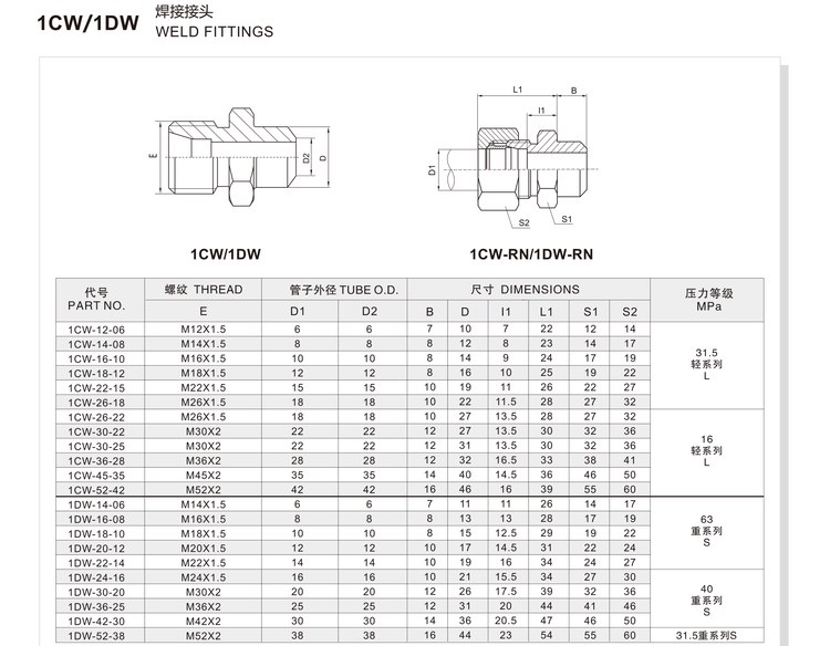
All dimensions in millimetres. Every row is transcribed from the current 1CW/1DW drawing.
| PART NO. | E THREAD | D1 | D2 | B | D | l1 | L1 | S1 | S2 | Pressure Group |
|---|---|---|---|---|---|---|---|---|---|---|
| 1CW-12-06 | M12X1.5 | 6 | 6 | 7 | 10 | 7 | 22 | 12 | 14 | 31.5 MPa, light series L |
| 1CW-14-08 | M14X1.5 | 8 | 8 | 8 | 12 | 8 | 23 | 14 | 17 | 31.5 MPa, light series L |
| 1CW-16-10 | M16X1.5 | 10 | 10 | 8 | 14 | 9 | 24 | 17 | 19 | 31.5 MPa, light series L |
| 1CW-18-12 | M18X1.5 | 12 | 12 | 8 | 16 | 10 | 25 | 19 | 22 | 31.5 MPa, light series L |
| 1CW-22-15 | M22X1.5 | 15 | 15 | 10 | 19 | 11 | 26 | 22 | 27 | 31.5 MPa, light series L |
| 1CW-26-18 | M26X1.5 | 18 | 18 | 10 | 22 | 11.5 | 28 | 27 | 32 | 31.5 MPa, light series L |
| 1CW-26-22 | M26X1.5 | 18 | 18 | 10 | 27 | 13.5 | 28 | 27 | 32 | 16 MPa, light series L |
| 1CW-30-22 | M30X2 | 22 | 22 | 12 | 27 | 13.5 | 30 | 32 | 36 | 16 MPa, light series L |
| 1CW-30-25 | M30X2 | 22 | 22 | 12 | 31 | 13.5 | 30 | 32 | 36 | 16 MPa, light series L |
| 1CW-36-28 | M36X2 | 28 | 28 | 12 | 32 | 16.5 | 33 | 38 | 41 | 16 MPa, light series L |
| 1CW-45-35 | M45X2 | 35 | 35 | 14 | 40 | 14.5 | 36 | 46 | 50 | 16 MPa, light series L |
| 1CW-52-42 | M52X2 | 42 | 42 | 16 | 46 | 16 | 39 | 55 | 60 | 16 MPa, light series L |
| 1DW-14-06 | M14X1.5 | 6 | 6 | 7 | 11 | 11 | 26 | 14 | 17 | 63 MPa, heavy series S |
| 1DW-16-08 | M16X1.5 | 8 | 8 | 8 | 13 | 13 | 28 | 17 | 19 | 63 MPa, heavy series S |
| 1DW-18-10 | M18X1.5 | 10 | 10 | 8 | 15 | 12.5 | 29 | 19 | 22 | 63 MPa, heavy series S |
| 1DW-20-12 | M20X1.5 | 12 | 12 | 10 | 17 | 14.5 | 31 | 22 | 24 | 63 MPa, heavy series S |
| 1DW-22-14 | M22X1.5 | 14 | 14 | 10 | 19 | 16 | 34 | 24 | 27 | 63 MPa, heavy series S |
| 1DW-24-16 | M24X1.5 | 16 | 16 | 10 | 21 | 15.5 | 34 | 27 | 30 | 63 MPa, heavy series S |
| 1DW-30-20 | M30X2 | 20 | 20 | 12 | 26 | 17.5 | 39 | 32 | 36 | 40 MPa, heavy series S |
| 1DW-36-25 | M36X2 | 25 | 25 | 12 | 31 | 20 | 44 | 41 | 46 | 40 MPa, heavy series S |
| 1DW-42-30 | M42X2 | 30 | 30 | 14 | 36 | 20.5 | 47 | 46 | 50 | 40 MPa, heavy series S |
| 1DW-52-38 | M52X2 | 38 | 38 | 16 | 44 | 23 | 54 | 55 | 60 | 31.5 MPa, heavy series S |
Reading the table: E is the stud thread, D1 is the tube outside diameter that the stud end serves, D2 is the tube outside diameter of the weld end, D and B are the weld geometry, and the pressure group applies to the whole row.
Note on two rows: the supplied drawing lists the same tube outside diameter for 1CW-26-18 and 1CW-26-22, and again for 1CW-30-22 and 1CW-30-25. If a step-up weld end is required on those rows, confirm the weld tube diameter against the drawing at the time of order.
Thread Size and Dash Chart
| E Thread (stud end) | Tube O.D. D1 / D2 | Catalogue Row | Pressure Group |
|---|---|---|---|
| M12X1.5 | 6 | 1CW-12-06 | 31.5 MPa, L |
| M14X1.5 | 8 | 1CW-14-08 | 31.5 MPa, L |
| M16X1.5 | 10 | 1CW-16-10 | 31.5 MPa, L |
| M18X1.5 | 12 | 1CW-18-12 | 31.5 MPa, L |
| M22X1.5 | 15 | 1CW-22-15 | 31.5 MPa, L |
| M26X1.5 | 18 | 1CW-26-18 | 31.5 MPa, L |
| M30X2 | 22 | 1CW-30-22 | 16 MPa, L |
| M36X2 | 28 | 1CW-36-28 | 16 MPa, L |
| M45X2 | 35 | 1CW-45-35 | 16 MPa, L |
| M52X2 | 42 | 1CW-52-42 | 16 MPa, L |
| M14X1.5 | 6 | 1DW-14-06 | 63 MPa, S |
| M16X1.5 | 8 | 1DW-16-08 | 63 MPa, S |
| M22X1.5 | 14 | 1DW-22-14 | 63 MPa, S |
| M24X1.5 | 16 | 1DW-24-16 | 63 MPa, S |
| M30X2 | 20 | 1DW-30-20 | 40 MPa, S |
| M36X2 | 25 | 1DW-36-25 | 40 MPa, S |
| M42X2 | 30 | 1DW-42-30 | 40 MPa, S |
| M52X2 | 38 | 1DW-52-38 | 31.5 MPa, S |
The same light series stud thread serves more than one weld tube size, so order by full part number and not by the stud thread alone.
Material y tratamiento térmico
| Artículo | Specification | Status |
|---|---|---|
| Body material | Carbon steel, machined from bar | Typical |
| Alternative material | Stainless steel on request | On request |
| Tratamiento térmico | Stress relief / hardening per part size and pressure group | Typical |
| Surface treatment | Zinc plating with trivalent passivation; other finishes on request | Typical |
| Weld end preparation | Square cut with deburred edge; joint preparation per the welding procedure | Typical |
| Thread inspection | Go / no-go gauge check | Typical |
| Documentation | Mill test report, dimensional report, pressure test record | On request |
Working Pressure and Operating Envelope
Working pressure is set by the pressure group of the row selected, together with the tube system, the weld quality and the hose assembly the adapter joins.
| Group from Drawing | Series | Typical Application Envelope |
|---|---|---|
| 31.5 MPa | Light series L | Light-series tube runs, D1 6-18 mm |
| 16 MPa | Light series L | Light-series runs with larger tube, D1 22-42 mm |
| 63 MPa | Heavy series S | High-pressure heavy-series runs, D1 6-14 mm |
| 40 MPa | Heavy series S | Heavy-series runs, D1 16-30 mm |
| 31.5 MPa | Heavy series S | Largest heavy-series row, D1 38 mm |
A welded tube joint adds its own limit: the weld itself must be rated for the group. The finished assembly is only as strong as its weakest member. (1 MPa is approximately 145 psi.)
Rango de temperatura
| Condition | Range | Notas |
|---|---|---|
| Typical service | -40 °C to +120 °C | Governed by the tube material, the weld procedure and the hose selected |
| Weld procedure | Qualified procedure for the tube and adapter materials | Typical |
| Low temperature | Below -40 °C | Confirm tube material and weld procedure before order |
| High temperature | Above +120 °C | Confirm tube material, weld procedure and hose before order |
Cómo interpretar la tabla de referencias
The code reads: series prefix, stud-end thread code, weld-end tube code, and an optional RN suffix. Prefix gives the series, the first block is the metric stud thread, and the second block is the tube size of the weld end.
- Prefix 1CW = light series; prefix 1DW = heavy series.
- First block: metric stud thread nominal diameter (14 = M14X1.5, 26 = M26X1.5).
- Second block: nominal tube size code (06 = 6 mm, 15 = 15 mm, 42 = 42 mm).
- Suffix RN = supplied as a complete set with cutting ring and nut for the tube end.
Example 1: 1CW-16-10 = light series, M16X1.5 stud end serving 10 mm tube, 10 mm weld end, weld boss D 14, insertion depth B 8, overall length 24, 31.5 MPa group.
Example 2: 1CW-52-42 = light series, M52X2 stud end serving 42 mm tube, 42 mm weld end, weld boss D 46, insertion depth B 16, overall length 39, 16 MPa group.
Example 3: 1DW-36-25 = heavy series, M36X2 stud end serving 25 mm tube, 25 mm weld end, weld boss D 31, insertion depth B 12, 40 MPa group.
Selección y pedido
Ordering the weld fitting hydraulic adapter 1CW/1DW is a four-step check: measure the tube outside diameter at both ends, confirm the stud thread, decide whether the tube joint must be welded or can use the RN ring and nut set, then compare the pressure group.
Selection Checklist and Decision Table
| Question | Answer | Consequence |
|---|---|---|
| What is the tube outside diameter at the weld end? | Match to D2 | Determines the weld boss D and insertion depth B |
| What is the stud thread on the tube nut side? | Match to E exactly | The stud thread and D1 must belong to the same series |
| Light or heavy series tube system? | Light L or heavy S | Determines 1CW versus 1DW and the pressure group |
| Is a welded joint acceptable on this run? | Welded = 1CW/1DW; demountable = RN version | The RN version is supplied with cutting ring and nut |
| Is the weld boss diameter D correct for the joint? | Match to the row | Wrong boss geometry changes the weld cross section |
| What is the system working pressure? | Compare with the group | A 16 MPa row must not be used on a 31.5 MPa line |
Servicio de referencias cruzadas
Send a photo or a dimension sketch of the adapter being replaced, or the tube sizes at both ends. We measure the stud thread, identify the tube series, record B, D, l1, L1, S1 and S2, then map the part to a 1CW/1DW row free of charge. We do not copy or re-badge another manufacturer’s part number.
Embalaje y logística
| Artículo | Standard Practice |
|---|---|
| Unit protection | Individually bagged with the weld end and thread protected |
| Carton marking | Part number, batch number, quantity, pressure group |
| RN sets | Cutting ring and nut supplied in the same bag with the adapter |
| Documentation | Mill test report and dimensional report travel with the batch on request |
| Mixed shipping | Mixed sizes combined in one shipment to control freight cost |
| Urgent orders | Air freight for urgent replacement quantities |
Installation and Fitment Guide
Step-by-Step Assembly
- Check the part number, the stud thread and the weld tube size against the order and against the tube on the bench.
- Cut the tube square, deburr it and clean it back to bare metal over the weld zone.
- Fit the adapter to the tube with the B insertion depth respected, and tack weld in two or three places before completing the root run.
- Complete the weld using a qualified procedure for the tube and adapter materials, and allow the part to cool without quenching in water.
- Clean the spatter and check the stud thread for damage before assembly, then fit the tube nut and ferrule or cone on the stud end and torque to the tube system table.
- Pressure test the finished run and check both the weld and the tube joint for weeping before the machine returns to service.
Torque and Sealing Notes
- Use the torque table for the exact thread size, material class and finish involved, taken from the applicable standard data sheet or the drawing supplied with the order.
- The weld joint is permanent, so the tube must be aligned before the root run. Correcting an alignment fault afterwards means cutting the weld out.
- Heat input matters. Weld to a qualified procedure, keep the arc away from the stud thread and the hex, and do not use the adapter body as an earth return.
- The stud end seals through the tube system’s own seat. Do not add sealant to the stud thread in place of a correct ferrule or cone joint.
- If a stud end weeps after correct torque, check the tube squareness and the ring or cone before adding more torque.
Advertencias sobre la instalación
- Do not use this adapter as a threaded part on the weld end; the weld neck is made for fusion welding only.
- Do not weld with the mating hose or tube nut assembled to the stud end, and do not weld through the adapter to a pressurised system.
- Do not interchange light series and heavy series parts, even where a thread appears to start.
- Do not substitute a 74 degree cone or a 60 degree seat stud end for the metric stud end shown here.
- Do not re-machine the weld boss or the insertion depth to make a joint fit; order the correct row instead.
- Do not exceed the pressure group of the selected row.
Applications and Industries
Weld-in tube runs on mobile equipment: the most common use is a pipe or tube run that must stay one piece from the valve block to the cylinder, with one stud end left free for service.
Replacing threaded nipples at the tube end: where a threaded nipple and hose tail have been a chronic weep point, the weld version removes both joints.
Cross-standard equipment integration: a machine with metric tube practice that needs a permanent tube connection at a bulkhead or manifold entry.
Repair and replacement: tube sizes at both ends can be measured on the bench, so an unidentified adapter can usually be matched to a row from dimensions alone.
High-pressure test benches: heavy series rows at 63 MPa and 40 MPa suit rigs that need a leak path closed permanently.
Industrial plant: presses, power units and machine tools where a welded tube joint is preferred for vibration resistance.
Industry tags: hydraulic adapter, weld fitting, weld-on nipple, metric stud end, DIN 2353, ISO 8434-1, tube adapter, hydraulic fitting.
Personalización OEM y trazabilidad de la calidad
We manufacture hydraulic adapters and hose assemblies and support OEM programs with private labelling and laser marking of your own part number on the hex or shank. Custom weld boss dimensions, special lengths, alternative materials and RN set combinations are quoted from your drawing or sample, usually within 24 hours.
Every production batch is traceable. Parts pass a 100 percent pressure test before packing, and mill test reports, dimensional inspection reports and pressure test records are available with the shipment on request. Third-party inspection such as BV or SGS can be arranged. Our manufacturing system is certified to ISO 9001:2015 and ISO 18752.
Preguntas frecuentes
Q: What makes the weld fitting hydraulic adapter 1CW/1DW different from a threaded nipple?
A: It replaces a threaded nipple with a fusion welded neck, so the tube run loses a threaded joint and the associated weep risk, while the stud end still uses the standard metric tube nut and ring or cone.
Q: Can the weld end be used with a nut instead of welding?
A: No. The weld neck has no sealing seat and no thread. It is designed for fusion welding to the tube only. If a demountable tube joint is needed, order the RN version, which is supplied complete with cutting ring and nut.
Q: What do the D and B columns mean?
A: D is the outside diameter of the weld boss and B is the insertion depth of the weld neck. Together they define the weld joint geometry for that row and should be used when preparing the tube.
Q: Is light series L interchangeable with heavy series S?
A: No. The two series have different tube wall thicknesses, thread sizes and pressure groups. A light series row is grouped at 31.5 MPa or 16 MPa, a heavy series row at 63 MPa, 40 MPa or 31.5 MPa on the largest size.
Q: What pressure can this adapter take?
A: The pressure group of the row governs the limit, and the welded joint and tube must be rated at or above that group. The finished assembly is only as strong as its weakest member.
Q: Which material and plating are standard?
A: Carbon steel with zinc plating and trivalent passivation is typical, with stainless steel and alternative finishes on request. State the tube material when ordering so the weld procedure can be matched.
Q: How do I identify a replacement for an unmarked adapter?
A: Measure the stud thread with a gauge and the tube diameter at the weld end, then send a photo or sketch. We map the part to a 1CW/1DW row free of charge and will not copy another manufacturer’s part number.
Q: What are your lead times?
A: Standard rows typically ship as a 7-day batch, custom sampling is available in about 48 hours for new drawings, and urgent quantities can move by air freight.
Solicitar un presupuesto
Send us the stud thread, the tube outside diameter at both ends, the tube series (light L or heavy S), the tube material and the quantity. With those five details we confirm the correct row of the weld fitting hydraulic adapter 1CW/1DW matrix, check the weld geometry and the pressure group, and return a quotation within 24 hours.
Browse the full Adaptadores hidráulicos range for the complete family, or contact us to request a quote, mill test reports, and samples.

 English
  Spanish
  Portuguese
  French
  German
  Arabic