
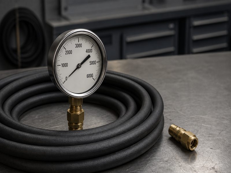
Working pressure is the highest pressure a hydraulic hose is designed to carry continuously in normal service. Burst pressure is the pressure at which the hose ruptures and fluid escapes. The working pressure vs burst pressure relationship for hydraulic hose is fixed. Minimum burst pressure must be at least four times the working pressure. That gap is the 4:1 safety factor (also written 4-to-1, or the burst-to-working pressure ratio).
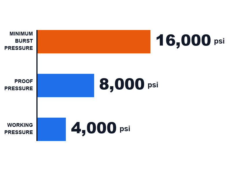
Select on working pressure, verify the minimum burst pressure behind it, and treat the 4:1 margin as a buffer, never as spare capacity. A 4,000 psi hose must be proven to survive at least 16,000 psi before it fails.
This guide shows where the 4:1 rule is written, in SAE J517, EN 853 and EN 856. It then works through the pressure ladder, the calculation methods in both directions, the conditions that consume the margin, and the markings printed on the hose itself.
1. Working Pressure vs Burst Pressure
Working pressure and burst pressure describe two different moments in a hose’s life. Working pressure is the ceiling for everyday operation. Burst pressure is the point of destruction. The 4:1 safety factor is the gap the industry deliberately maintains between them.
| Term | What it means | What it is used for | Value for a 4,000 psi hose |
|---|---|---|---|
| Maximum working pressure (WP) | The highest pressure the hose is designed to carry continuously in normal service | Hose selection and system design | 4,000 psi / 276 bar |
| Proof pressure | A non-destructive test pressure applied to the assembly and held for a fixed time | Production quality control | 6,000–8,000 psi, depending on the standard |
| Minimum burst pressure | The lowest pressure at which the hose is permitted to rupture | Verifying the safety margin | 16,000 psi minimum |
| Safety factor | Minimum burst pressure ÷ working pressure | The design margin itself | 4:1 |
The practical consequence is simple. A 4,000 psi hose is not a hose that “can probably take a bit more than 4,000 psi”. It is a hose that is engineered, tested and documented to survive at least 16,000 psi before it fails. The 12,000 psi behind it absorbs everything the real world throws at the assembly, and you never design to that figure directly. In other words, the working pressure vs burst pressure gap is a buffer you rely on, never a target you design to.
Scope of this guide: hydraulic hose under SAE J517, EN 853 and EN 856, and oil suction and discharge hose under EN 1765 / DIN 20023 / ISO 1823. The 4:1 minimum burst-to-working ratio applies to the hydraulic hose family at rated temperature, rated bend radius and rated impulse life. For low-pressure water hose under 150 psi, the factor is 3:1. For severe-service steam hose, use the factor specified for that product, which reaches 20:1. For hose operated outside its rated temperature or bend radius, derate the working pressure before selecting (see Section 10).
Why designers do not simply rate the hose at 16,000 psi and be done with it
The margin exists because the operating environment is not the test bench. Pressure spikes, thermal cycling, bending, abrasion and ageing all reduce what a hose can actually withstand. The 4:1 factor is a buffer for the difference between a laboratory and a machine.
2. Which Pressure Term Do You Need: Working, Operating, Rated, Design, Test, Proof, Burst or Failure?
Eight terms circulate in hose specification, and only three of them appear on a standard pressure table. Working pressure, proof pressure and minimum burst pressure are the published figures. Operating pressure, design pressure, rated pressure, test pressure and failure pressure are working terms, and suppliers use them inconsistently. This section is a quick-reference map rather than a starting point: the terms below are used in Sections 3 to 7, so it works equally well as a look-up after you have read those sections.
| Term | What it refers to | Multiple of working pressure | Destructive? | Where it comes from |
|---|---|---|---|---|
| Maximum working pressure (WP) | The highest pressure the hose is designed to carry continuously at its rated temperature | 1× — the reference point | No — it is a rating, not a test | Published in the hose standard |
| Operating pressure | The pressure the system actually sees in service, including normal duty-cycle variation | At or below 1× | No | Machine specification, not the hose standard |
| Rated pressure | Supplier shorthand for whichever limit the datasheet is quoting — usually working pressure, sometimes proof pressure | 1× or 1.5–2×, depending on which limit is meant | No | The supplier’s datasheet only; ask which limit it means |
| Design pressure | The highest pressure the system is designed for, after the relief setting and the designer’s transient allowance are applied | System pressure plus the chosen allowance | No | Your own system specification |
| Proof pressure | A non-destructive test pressure applied to the assembly and held for a fixed time | 1.5× (industrial tables) or 2× (EN 853 / EN 856 tables) | No — the assembly enters service afterwards | Published in the hose standard |
| Presión de prueba | Any pressure applied during a test; in practice it means the proof pressure unless the document states otherwise | Same as proof pressure, unless stated otherwise | Depends on which test is meant | The test report or test procedure |
| Minimum burst pressure | The lowest pressure at which the hose is permitted to rupture | 4:1 — the floor the standard sets | Yes — the sample is scrapped | Published in the hose standard |
| Failure pressure | The pressure at which a specific sample actually failed during a test | Usually above the minimum burst figure | Yes | The individual test report |
Which of these terms are you actually buying on?
Three of the eight appear in a published standard table, and only two of those are contractual. Working pressure and minimum burst pressure are the figures a supplier is held to, because both appear in the published standard. Proof pressure is the third published figure, and it is a quality gate rather than a rating. That leaves five working terms — operating, rated, design, test and failure — which describe how a specific system or a specific test report is being discussed. When two datasheets disagree, the fastest way to find out whether it matters is to ask which of the two contractual figures each one is quoting.
3. What Is Working Pressure, and Why Is It a Continuous Limit?
Working pressure, often printed as “WP” or “Max. W.P.”, is the maximum pressure a hose assembly is rated to withstand continuously, at its rated temperature, without a reduction in service life. It is a continuous rating, not a peak rating, and every other number on a hose datasheet is derived from it.
Why “continuous” is the operative word
A hose does not fail because of one loud event. In most field failures, the reinforcement fatigues over thousands of ordinary pressure cycles until the wire strands or textile plies finally give way. Working pressure is set at a level the reinforcement can sustain cycle after cycle for the rated impulse life of the hose.
That is why a hose that sees 4,000 psi all day is a safe design at 4,000 psi working pressure. A hose that briefly touches 4,000 psi inside a 3,000 psi system is not the same case at all.
How working pressure is established
Manufacturers do not guess the number. Working pressure is the outcome of three things:
- Reinforcement strength. The number of steel wire braids or spiral layers, the tensile strength of the wire, and the angle at which it is wound all determine how much hoop stress the hose can contain.
- Bore size. Pressure acts on the whole internal circumference. A larger bore presents more area for the same pressure to push against, so working pressure falls as the diameter rises — a pattern visible in every hydraulic hose pressure rating chart.
- The standard’s design factor. Once the reinforcement’s capability is known, SAE J517 (published by SAE International) or EN 853 (published by CEN) fixes the working pressure at a defined fraction of it. For hydraulic hose that fraction is one quarter.
Ratings That Sit Outside Working Pressure
The working pressure rating covers one thing: continuous pressure at rated temperature. Three separate ratings cover the conditions it does not reach, and each has its own limit on the datasheet:
- Vacuum rating. A hose can carry high internal pressure and still collapse under suction if it is not built for full vacuum.
- Minimum bend radius. A rating measured at the published bend radius does not transfer to a tighter bend.
- Impulse life. The number of pressure cycles the construction survives at the impulse test pressure, which is independent of the static burst figure.
A hose can be excellent at one of these and mediocre at another, which is why all three are quoted separately rather than folded into the pressure rating.
4. What Is Burst Pressure, and Why Only Minimum Burst Matters?
Hydraulic hose burst pressure is the pressure at which a hose ruptures and the hydraulic fluid escapes, a destructive and one-way event. On a datasheet it almost always appears as minimum burst pressure, and that word is doing important work.
The difference between “burst” and “minimum burst”
The standard’s boundary rule: the lowest burst pressure a construction can be relied on to deliver must be at least four times the hose’s rated working pressure. That is the floor the standard enforces. Individual samples usually rupture higher, which is expected and irrelevant to selection — the published figure is the guaranteed minimum, and it is the only number you may design against.
The reason for a floor rather than a typical value is production variation. Wire tensile strength varies slightly, braid tension varies slightly, and adhesion between layers varies slightly from lot to lot. A rating built on a typical result would be a rating built on the best samples.
How burst pressure is measured
Burst testing is a hydrostatic test: the assembly is filled with water or hydraulic fluid, all air is vented, and pressure is raised at a controlled rate until failure. Two points matter if you are reading a test report:
- The test is destructive. The sample is scrapped. A burst test result is evidence about a production lot, never a certificate about the hose in your hand.
- The failure point is defined. A leak at a fitting, a rupture through the cover, and a lengthwise split through the reinforcement are all failures, and all of them count against the same number.
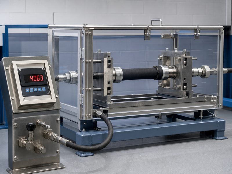
The applicable test methods are ISO 1402 (published by ISO) for rubber and plastics hoses, and SAE J343 (published by SAE International) for the SAE hydraulic hose family. Neither standard invents a new safety factor. They standardise how the existing one is proved.
A hose rated 4,000 psi burst at 17,400 psi in the lab — can I rate it higher?
No. The rating is a floor for the population, not a result for one sample. A single 17,400 psi rupture on a 4,000 psi hose is a healthy margin above the 16,000 psi minimum, and that is all it proves. To rate the product higher you would need the construction’s guaranteed minimum burst to rise, which means more reinforcement, a different type, or a different bore — not a better sample. The 4:1 rule is applied to the guaranteed minimum because that is the figure every unit in the lot is held to.
Why do hydraulic hoses burst? Field failure causes ranked
Burst failures are rarely caused by the pressure rating itself. A working pressure rating is a static number, while the mechanisms below account for most of the field failures we see, listed from the most common to the least:
- Pressure spikes and surges. Valve closures, reversing loads and cylinders hitting end stops push peak pressure well above the steady reading on the gauge. The spikes are measured in milliseconds and are usually invisible on a system gauge.
- Reinforcement fatigue at high cycle counts. A circuit that cycles several times a minute accumulates fatigue damage independently of peak pressure, and the hose fails well below its static burst figure.
- Damage at the crimp or fitting. A large share of field failures begin at the joint. A correctly rated hose with a poor crimp has no usable safety factor.
- Bend radius violations and external damage. Routing tighter than the published minimum bend radius concentrates stress on one side of the reinforcement, and cuts or gouges that reach the wire remove the pressure-containing structure locally.
- Temperature outside the rated range. Time above the compound’s continuous limit softens the rubber that transfers load into the reinforcement, so the assembly fails below its published burst figure.
- Fluid incompatibility and internal ageing. An incompatible fluid attacks the inner tube from the inside, where reinforcement strength cannot compensate.
The practical lesson is that the 4:1 ratio protects you against the first two mechanisms only when the last four are controlled. Selection is a pressure calculation; reliability is an installation and maintenance discipline.
5. Where Does the 4:1 Safety Factor Come From?
The 4:1 factor is a written requirement in the hose standards, not a marketing convention or a manufacturer’s preference. It formalises the working pressure vs burst pressure gap: minimum burst pressure must be at least four times the maximum working pressure.
The formula
\text{Safety factor} = \frac{\text{Minimum burst pressure}}{\text{Maximum working pressure}}
Rearranged, the two forms you will actually use in practice:
\text{Minimum burst pressure} = \text{Working pressure} \times 4
\text{Maximum working pressure} = \frac{\text{Minimum burst pressure}}{4}
Why four, and not two?
Four is the factor engineering practice arrived at because five separate mechanisms consume margin simultaneously. A hose has to survive steady pressure plus everything below happening at once:
- Pressure spikes and surges. Closing a valve, reversing a cylinder or hitting a load momentarily pushes internal pressure far above the steady operating pressure. These transients are counted in milliseconds but they stress the reinforcement every time.
- Impulse fatigue. Hydraulic circuits cycle, and each cycle flexes the steel wire. The margin has to cover fatigue damage accumulated across hundreds of thousands of cycles, not just the pressure of any single one.
- Temperature. Elastomer tube and cover compounds soften as they heat up, and the reinforcement loses some of its grip on the layers around it.
- Ageing and the environment. Ozone, UV, heat and abrasion degrade the cover and tube over months and years, slowly reducing the pressure the assembly can hold.
- Manufacturing and assembly variation. Crimp diameter, reinforcement tension and compound dispersion all vary slightly between lots and between assembly benches.
Conditions Outside the 4:1 Factor’s Scope
Applies to: normal service at rated pressure, rated temperature and rated bend radius. Beyond that scope the margin is consumed rather than absorbed. The four conditions that consume it most often — bending tighter than the minimum bend radius, incompatible fluid, external mechanical damage, and fitting or crimp defects — are ranked with the other failure mechanisms in Section 4 and set out condition by condition in Table 8.
6. What Is the Pressure Ladder? Working, Proof, Burst and Minimum Burst Explained
Three pressures appear on hydraulic hose datasheets, and they form a ladder rather than a pair. Understanding the ladder prevents the single most common specification error: reading the proof pressure and assuming it is the burst pressure.
| Rung | Relationship to working pressure | Applies to | 10 bar industrial hose | 4,000 psi hydraulic hose |
|---|---|---|---|---|
| Maximum working pressure | 1× — the design limit | Every hose type | 10 bar / 145 psi | 4,000 psi / 276 bar |
| Proof pressure (industrial tables) | 1.5× — non-destructive | General industrial hose, and customer specifications that call for 1.5× | 15 bar / 218 psi | 6,000 psi / 414 bar * |
| Proof pressure (EN 853 / EN 856 tables) | 2× — non-destructive | Wire-braid and wire-spiral hydraulic hose | 20 bar / 290 psi | 8,000 psi / 552 bar |
| Minimum burst pressure | 4:1 — destructive | Every hose type in this guide | 40 bar / 580 psi | 16,000 psi / 1,103 bar |
\* The 1.5× rung is the one that does not apply to EN 853 / EN 856 hydraulic hose unless the product specification calls for it. For those standards the proof value on a 4,000 psi hose is 8,000 psi. Confirm which proof value a supplier is quoting before comparing two datasheets.
Proof Pressure vs Burst Pressure: Not the Same Test
One is a pass/fail production gate; the other destroys the sample. This is the distinction that trips up even experienced buyers:
- The proof test is a pass/fail production test. The assembly is pressurised to the proof pressure and held for a defined period. It must show no leakage, no weeping and no permanent deformation, and it then goes into service. The test has not damaged it.
- The burst test is a destructive type test. A sample is pressurised until it fails. The result proves the construction meets the minimum burst requirement, and the sample is then scrapped.
The supplier quotes a 1.5× proof pressure on a hydraulic hose — is that acceptable?
It is acceptable for an industrial hose and unusual for a hydraulic hose built to EN 853 or EN 856. In those published tables the proof pressure is twice the working pressure. A hydraulic hose quoted at 1.5× is therefore one of three things: it is not built to those standards, the supplier is quoting a different figure under the same label, or the proof value on that datasheet belongs to a different product family. The check takes one question and one multiplication. Ask which standard the hose is built to, then confirm the working pressure and minimum burst pressure still sit in a 4:1 relationship. If they do, the proof number is a documentation question rather than a safety question.
Why proof pressure is not always the same multiple
The 4:1 burst requirement is fixed; the proof pressure is not. It is set by whichever standard governs the hose, and it varies between product families:
- In the published EN 853 (1SN / 2SN) and EN 856 (4SP / 4SH) hydraulic hose tables, the proof pressure is twice the maximum working pressure.
- For many industrial hoses — oil suction and discharge hose to EN 1765 and DIN 20023, for example — the proof test is commonly specified at 1.5 times the working pressure.
- Some customer and assembly specifications call for their own proof value, often 1.5×.
The lesson for anyone comparing supplier datasheets: always confirm which proof pressure you are being quoted, because 1.5× and 2× are both legitimate and both appear in real documents for different products. The burst ratio, by contrast, is 4:1 across the hydraulic hose family. Published table pairs can still show 3.95–4.00 because of preferred-value rounding, which is explained in the note under Table 6. When a supplier’s proof number looks low, check the working and burst figures rather than assuming the hose is weak.
7. How Does Working Pressure vs Burst Pressure Differ by Hose Standard?
The hydraulic hose safety factor of 4:1 is quoted so often that it is easy to assume it is universal. It is not. The ratio is fixed by whichever standard the hose is built to, and it differs between hydraulic hose and general industrial hose. A hydraulic hose working pressure figure quoted without its standard is therefore only half the information.
| Hose category and governing standard | Design factor set by the standard | Proof test set by the standard | As supplied by HENGHUA |
|---|---|---|---|
| Hydraulic hose — SAE J517 (SAE 100R series) | 4:1 | 2 × working pressure | 4:1; proof test to the governing standard |
| Hydraulic hose — EN 853 (wire braid, 1SN / 2SN) | 4:1 | 2 × working pressure | 4:1; proof test to the governing standard |
| Hydraulic hose — EN 856 (wire spiral, 4SP / 4SH) | 4:1 | 2 × working pressure | 4:1; proof test to the governing standard |
| Oil suction and discharge — EN 1765 / DIN 20023 / ISO 1823 | The standard sets no single factor; the rating is backed by burst testing | 1.5 × working pressure | 4:1 minimum burst-to-working ratio, confirmed on the datasheet for the size ordered |
| General industrial hose | Commonly 4:1 | — | 4:1 on standard supply |
| Low-pressure water hose rated under 150 psi | 3:1 | — | 3:1 |
| Steam hose in severe service | Substantially higher — up to 20:1 in some products | — | Product-specific; confirmed per application |
Table note: the “As supplied by HENGHUA” column records how these product families are built and tested in our own production, and comes from HENGHUA product data rather than from a standard. Proof values shown as “—” are set by the individual product standard and by the customer specification, so no single value applies across the family and the column is deliberately left blank rather than implying one.
Why industrial hose can use a lower factor than hydraulic hose
The reason is the service, not the rubber. A hydraulic circuit is a high-cycle, high-surge environment: the hose is flexed, the pressure pulses, and a failure releases a stream of fluid at high velocity. A low-pressure water or general industrial hose operates at low pressure with few transients, so a smaller margin is sufficient. Steam hose is the opposite extreme. The stored energy in hot steam makes a small margin unacceptable, so the factor rises sharply.
4:1, 3:1 and 20:1 in one page: why the same word means different margins by product family
The words “safety factor” stay the same across product families while the number changes, so the factor must always be read with the standard attached. One maintenance bay can hold all three cases at once:
- 4:1 — hydraulic hose. A 1/2 in 2SN hose rated 3,990 psi sits on a 3,000 psi circuit. Its minimum burst pressure floor is 3,990 × 4 = 15,960 psi, and that margin is what absorbs the spikes the circuit produces.
- 3:1 — low-pressure water hose. A wash-down hose rated under 150 psi is built to 3:1. Substituting it into the hydraulic circuit above would place a 3:1 product in a high-surge duty it was never designed for, whatever the pressure numbers on the two labels happen to be.
- 20:1 — severe-service steam hose. On a steam line, the stored energy in the fluid, not the pump, sets the failure severity, which is why some products carry a margin several times larger than the hydraulic case.
The selection rule that follows: never carry a safety factor from one product family to another. Read the factor from the standard that governs the hose you are installing, then verify the two figures that carry it.
Do I need a different safety factor for a hose carrying hot oil rather than hydraulic fluid?
The factor stays at 4:1; the working pressure you may use does not. Oil suction and discharge hose under EN 1765, DIN 20023 or ISO 1823 is rated for a temperature range as well as a pressure, and the pressure figure applies only inside that range. Hot oil inside the rated temperature range keeps the standard factor. Hot oil above the compound’s continuous limit reduces the usable working pressure, which is a derating question rather than a safety factor question, and Section 10 covers it. The two documents that decide the answer are the datasheet’s continuous temperature limit and the fluid compatibility chart for the tube compound. Ordering on pressure alone is how a correctly rated hose ends up being run outside its rating.
Where the 4:1 rule is written
The requirement lives in the published standards, and the figures in this guide are the preferred values those standards publish. If you need to point at a document rather than a supplier’s datasheet, these are the ones that carry the requirement:
- SAE J517, SAE 100R series pressure ratings table (SAE International) — the parent specification listing the SAE 100R hose types, their construction requirements and their pressure ratings, applying a 4:1 design factor across the hydraulic family.
- EN 853, 1SN / 2SN working pressure table (CEN) — European standard for wire-braid hydraulic hose, covering 1SN (single braid) and 2SN (double braid).
- EN 856, 4SP / 4SH minimum burst pressure table (CEN) — European standard for wire-spiral hydraulic hose, covering 4SP and 4SH.
- EN 857, compact wire-braid hydraulic hose (1SC / 2SC) (CEN) — used where bend radius matters more than bore; its working pressures are tabulated separately for the 1SC and 2SC types.
- ISO 1436 and ISO 3862 (ISO) — the international equivalents for wire-braid and wire-spiral hydraulic hose, specified to the same 4:1 design factor.
- ISO 1402, hydrostatic test method for rubber and plastics hoses (ISO), and SAE J343 (SAE International) — the test procedures that accompany the SAE 100R hose family. These are the methods used to prove the factor.
- EN 1765, DIN 20023 and ISO 1823 — three separate documents for oil suction and discharge hose, not three numbers for one standard. EN 1765 is the European product standard, DIN 20023 is the German standard for the same product family, and ISO 1823 is the international standard. A quotation may name any one of them, and where they differ, the buyer’s specification decides which applies. Our own oil suction and discharge hose guide sets out how those ratings are applied in practice.
Elsewhere in this guide, standard references use the same locators: pressure ratings are read from the working pressure and minimum burst pressure tables named above, and test requirements from the test-method documents named above.
For a clause-by-clause walkthrough of the SAE side of the family, see our SAE J517 complete guide; for a side-by-side of the European, American and Chinese systems, see the SAE vs DIN vs ISO vs GB comparison.
One practical warning about comparing standards: a hydraulic hose can be graded by construction (SAE 100R2, EN 853 2SN) or by impulse performance (ISO 18752 Grades A to D). These are different axes. A hose selected on impulse grade may carry a working pressure that looks similar to a construction-based type while its burst ratio is arrived at differently. Always confirm the factor on the datasheet you are actually buying against, not on a similar-looking product from another family. The same discipline applies when you compare hydraulic hose working pressure figures between suppliers: the numbers are only comparable if the construction and the governing standard match.
Data source for the pressure tables in this guide: the working pressure and minimum burst pressure figures quoted here are the preferred (published) values from the EN 853, EN 856 and SAE J517 pressure tables, at rated temperature. Confirm the exact published value for the type and size you are ordering against the standard or the manufacturer’s datasheet before you specify, and treat any figure that cannot be traced to one of those tables as unverified.
Related guides by hose type
This guide covers the pressure relationship itself. The same 4:1 rule applied to a specific hose family, with that family’s own pressure tables and applications, is covered in:
8. How Do I Read Working Pressure and Minimum Burst Pressure From a Rating Chart?
Pressure ratings fall as bore rises, and the fall is steep. The reference tables below let you read the hydraulic hose pressure rating directly by dash size, then apply the 4:1 rule to get the minimum burst pressure the hose must deliver. Read the rating at the dash size you are installing, because scaling a number down from a smaller size is one of the most common specification errors in hydraulic hose selection.
EN 853 and EN 856 hydraulic hose working pressure by dash size
| Dash size | Nominal ID | 1SN (1 braid) | 2SN (2 braids) | 4SP (4 spiral) | 4SH (4 spiral, heavy) |
|---|---|---|---|---|---|
| -04 | 1/4 in | 3,260 psi / 225 bar | 5,800 psi / 400 bar | 6,525 psi / 450 bar | — |
| -06 | 3/8 in | 2,610 psi / 180 bar | 4,785 psi / 330 bar | 6,450 psi / 445 bar | — |
| -08 | 1/2 in | 2,320 psi / 160 bar | 3,990 psi / 275 bar | 6,020 psi / 415 bar | — |
| -12 | 3/4 in | 1,520 psi / 105 bar | 3,120 psi / 215 bar | 5,075 psi / 350 bar | 6,090 psi / 420 bar |
| -16 | 1 in | 1,280 psi / 88 bar | 2,390 psi / 165 bar | 4,060 psi / 280 bar | 5,510 psi / 380 bar |
| -20 | 1-1/4 in | 910 psi / 63 bar | 1,810 psi / 125 bar | 3,045 psi / 210 bar | 4,710 psi / 325 bar |
| -24 | 1-1/2 in | 725 psi / 50 bar | 1,305 psi / 90 bar | 2,680 psi / 185 bar | 4,205 psi / 290 bar |
| -32 | 2 in | 580 psi / 40 bar | 1,160 psi / 80 bar | — | 3,625 psi / 250 bar |
Read that table against the 4:1 rule and the hydraulic hose burst pressure behind each rating becomes a large number. A 1/2 in 2SN hose rated 3,990 psi must survive at least 15,960 psi before it fails. A 3/4 in 4SH hose rated 6,090 psi must survive at least 24,360 psi.
Two burst figures appear in the standards — but only where the published table rounds
| Hose type | Dash size and ID | Presión de trabajo | Minimum burst pressure (working pressure × 4) | Minimum burst pressure (published EN 853 / EN 856 value) |
|---|---|---|---|---|
| EN 853 1SN | -06 / 3/8 in | 2,610 psi / 180 bar | 10,440 psi / 720 bar | 10,440 psi / 720 bar |
| EN 853 2SN | -06 / 3/8 in | 4,785 psi / 330 bar | 19,140 psi / 1,320 bar | 19,140 psi / 1,320 bar |
| EN 853 2SN | -12 / 3/4 in | 3,120 psi / 215 bar | 12,480 psi / 860 bar | 12,325 psi / 850 bar |
| EN 856 4SP | -06 / 3/8 in | 6,450 psi / 445 bar | 25,800 psi / 1,780 bar | 25,800 psi / 1,780 bar |
| EN 856 4SH | -12 / 3/4 in | 6,090 psi / 420 bar | 24,360 psi / 1,680 bar | 24,360 psi / 1,680 bar |
| EN 853 1SN | -16 / 1 in | 1,280 psi / 88 bar | 5,120 psi / 352 bar | 5,075 psi / 350 bar |
| EN 856 4SH | -32 / 2 in | 3,625 psi / 250 bar | 14,500 psi / 1,000 bar | 14,500 psi / 1,000 bar |
Note on the two burst columns: for most sizes the published value and the working-pressure × 4 floor are the same figure, and they diverge only where the standard rounds to a preferred number. The “working pressure × 4” column is the floor the standard sets, and it is the figure to hold a supplier to. The “published value” column is the preferred (rounded) figure printed in the EN 853 and EN 856 pressure tables. Where a standard table rounds to a preferred number, dividing the published pair gives slightly less than 4.00 — EN 853 2SN -12 is 850 ÷ 215 = 3.95, and EN 853 1SN -16 is 350 ÷ 88 = 3.98. The requirement is a floor, not an equality: minimum burst pressure must be at least four times working pressure. For the exact figures on the size you are ordering, read them from the standard’s table or the manufacturer’s datasheet rather than back-calculating from a rounded pair.
Data source: EN 853 (1SN / 2SN) and EN 856 (4SP / 4SH) published pressure tables, at rated temperature. The “working pressure × 4” column is computed from the published working pressure; the “published value” column is the preferred figure as printed. Confirm the published value for the size you order against the standard or the manufacturer’s datasheet.
Can I use a 100R2 hose at 2 in bore where my drawing calls for 5,000 psi?
No. The bore decides this, not the type. 100R2 is a two-wire-braid construction, and its working pressure falls steeply with bore: Table 7 shows 6,000 psi at -04, 4,000 psi at -08, and 1,150 psi at -32. A 2 in bore inside a 5,000 psi circuit therefore needs a spiral construction, where 100R13 holds 5,000 psi and 100R15 holds 6,000 psi at that dash size. Two options follow: move to the spiral type, or reduce the bore. Scaling the -08 rating up to 2 in is not a third option, because working pressure is established per dash size.
SAE 100 series hydraulic hose working pressure by dash size
| Dash size | Nominal ID | 100R1 | 100R2 | 100R12 | 100R13 | 100R15 | 100R16 |
|---|---|---|---|---|---|---|---|
| -04 | 1/4 in | 3,250 | 6,000 | — | — | — | 5,800 |
| -06 | 3/8 in | 2,800 | 5,000 | 4,000 | — | — | 5,800 |
| -08 | 1/2 in | 2,500 | 4,000 | 4,000 | 5,000 | 6,000 | 4,000 |
| -12 | 3/4 in | 1,600 | 3,000 | 3,000 | 5,000 | 6,000 | 3,000 |
| -16 | 1 in | 1,250 | 2,500 | 2,500 | 5,000 | 6,000 | 2,500 |
| -32 | 2 in | 575 | 1,150 | 2,500 | 5,000 | — | — |
Data source: published SAE J517 maximum working pressure values for the SAE 100R types shown, at a 4:1 design factor. Values are the standard’s preferred figures in psi at rated temperature. Confirm the published value for the type and size you order against SAE J517 or the manufacturer’s datasheet, and remember that the minimum burst floor is this figure multiplied by four.
The pattern to notice is that the spiral types hold pressure far better as bore grows. 100R13 and 100R15 stay at 5,000 and 6,000 psi all the way to 2 in bore, while 100R2 falls from 6,000 psi at -04 to 1,150 psi at -32, a drop of more than 80 percent. If your large-bore circuit runs at high pressure, the hydraulic hose pressure rating chart will usually push you toward a spiral construction, and the 4:1 rule then applies to a much higher base number. Our braided vs spiral construction comparison covers the reinforcement side of that decision.
Need the full chart in one place? Request the full pressure rating chart for EN 853, EN 856 and the SAE 100R series, with working pressure and minimum burst pressure listed by dash size, and we will send it with the datasheets for the types you specify.
9. How Do I Calculate Working Pressure and Burst Pressure?
Three relationships cover almost every calculation you will need, and all three are pure arithmetic. That is deliberate. A safety factor that required interpretation would not be a safety factor.
Relationship 1: hydraulic hose safety factor from two known pressures
\text{Safety factor} = \frac{\text{Minimum burst pressure}}{\text{Maximum working pressure}}
A hydraulic hose safety factor is nothing more than the ratio between the two published figures, which is why one division checks it. If a datasheet lists a 6,090 psi working pressure and a 24,360 psi minimum burst pressure, the factor is 24,360 ÷ 6,090 = 4.0. If the result comes out at 3.0, you are looking at an industrial hose or a non-standard product rather than a 4:1 hydraulic hose, and the two documents should be treated as describing different products. Values between 3.95 and 4.00 come from preferred-value rounding in the published standard tables rather than from a reduced factor — the note under Table 6 works through two examples — while a result near 3.0 is a different construction.
Relationship 2: minimum burst pressure from working pressure
\text{Minimum burst pressure} = \text{Maximum working pressure} \times 4
This is the direction you use most often when specifying, and it runs in two steps. If your relief valve is set to 2,500 psi and the circuit has sharp valve closures, the design pressure is 2,500 × 1.25 = 3,125 psi. The hose you select must therefore have a working pressure of at least 3,125 psi, which sets a minimum burst pressure floor of 3,125 × 4 = 12,500 psi.
Relationship 3: working pressure from a measured burst result
\text{Maximum working pressure} = \frac{\text{Minimum burst pressure}}{4}
This is the direction used after a burst test, when a hydraulic hose burst pressure result needs to be converted back into a rating. If a sample from a production lot bursts at 19,140 psi, the highest working pressure that lot can be rated for is 19,140 ÷ 4 = 4,785 psi, which is exactly the published figure for an EN 853 2SN hose in 3/8 in bore. When a supplier’s burst test result and their quoted working pressure do not reconcile through this division, one of the two numbers is wrong.
How burst pressure scales with construction
Four physical variables move the burst pressure, and they are the ones that decide the working pressure you can order:
- More reinforcement layers raise burst pressure approximately in proportion. A two-braid hose is not exactly twice as strong as a one-braid hose, because the layers interfere with each other and the outer layer does less work, but the increase is substantial and predictable.
- A larger bore lowers the achievable working pressure for a given reinforcement. In the EN 853 2SN column of Table 5, working pressure falls from 5,800 psi / 400 bar at -04 / 1/4 in to 1,160 psi / 80 bar at -32 / 2 in, a 5.0× reduction across an 8× increase in bore. Working pressure falls as bore rises because hoop stress in the reinforcement increases with bore diameter at a given pressure, so a fixed reinforcement contains less pressure as the bore grows. The reduction is smaller than the 8× bore increase because larger sizes are built with proportionally heavier reinforcement.
- Higher wire tensile strength raises burst pressure directly. This is why wire grade and adhesion quality, not just layer count, separate a good hose from a marginal one at the same nominal specification.
- Temperature lowers the achievable burst pressure by softening the rubber that holds the reinforcement in place, which is why every credible datasheet lists a temperature range alongside the pressure rating.
Worked example: replacing a return line on a hydraulic press
A workshop is replacing the return line on a hydraulic press. The relief valve is set at 3,000 psi, the run is short with a tight 4 in bend, and the fluid runs at about 80 °C.
- Establish the design pressure. System pressure including the relief setting is 3,000 psi. Add the transient allowance: for intermittent spikes, 3,000 × 1.25 = 3,750 psi, so the hose must be rated at 3,750 psi or above, not exactly at 3,000 psi.
- Select a hose whose working pressure clears the requirement. Our SAE 100R2 hose in -08 has a working pressure of 4,000 psi, which clears the 3,750 psi design pressure with margin. SAE 100R1 in -08 at 2,500 psi does not, because it sits below the relief setting.
- Verify the minimum burst pressure. 4,000 × 4 = 16,000 psi, so the datasheet must state a minimum burst pressure of at least 16,000 psi.
- Confirm the proof test. The proof value is set by the standard the hose is built to rather than by a single industry-wide number. The published EN 853 (1SN / 2SN) and EN 856 (4SP / 4SH) tables specify twice the working pressure, which is 8,000 psi on a 4,000 psi hose. For the SAE J517 type, use the proof value listed against that type in the standard. Whichever you buy, ask the supplier to state both the proof value and the standard it comes from, then check the two against each other.
- Check the secondary limits. Minimum bend radius must be within the 4 in available, and the temperature rating must cover 80 °C with margin. Neither of these is negotiable because the pressure rating passed.
The arithmetic took two multiplications. The judgement — surge allowance, bend radius, temperature — took the rest, and that judgement is where most real failures originate.
10. When Does the 4:1 Factor Shrink, and by How Much?
The 4:1 safety factor is quoted against the hose’s rated conditions, and moving outside those conditions narrows the effective margin even though the datasheet numbers have not changed. This is where the working pressure vs burst pressure relationship stops being theoretical and starts predicting service life.
| Condition in service | Why it consumes margin | What to do about it |
|---|---|---|
| Fluid temperature above 100 °C | Standard nitrile tube and cover compounds soften, and the reinforcement loses grip on the layers around it | Derate working pressure, commonly by about 1.5 percent per °C above 100 °C, or move to a higher-temperature construction |
| Pressure spikes above working pressure | Each transient loads the reinforcement beyond its steady-state duty | Keep transients within about 125 percent of working pressure for intermittent duty, and size the hose above the relief valve setting |
| Sustained operation above working pressure | Accelerates reinforcement fatigue and shortens service life disproportionately | Operating limit: keep continuous pressure at or below the rated working pressure at all times. Sustained overpressure consumes the margin the 4:1 factor exists to protect. |
| Bending tighter than the minimum bend radius | Concentrates stress on one side of the reinforcement and can progressively deform the bore | Route to the published bend radius or move to a compact hose type |
| High impulse cycle counts | Fatigues the steel wire one cycle at a time until strands break | Specify a spiral construction with a higher impulse rating rather than adding pressure margin |
| Incompatible hydraulic fluid | Attacks and swells the inner tube from the inside, where no reinforcement can help | Match the tube compound to the fluid before selecting anything else |
| Cover abrasion, cutting or ozone cracking | Removes the protection around the reinforcement and can breach it directly | Action required: 1) Take the hose out of service. 2) Replace it. Pressure derating does not restore the reinforcement or the cover. |
| Crimp or fitting defect | Removes margin without any external sign | Verify crimp diameter against the assembly specification and proof-test the assembly |
Why temperature derating matters more than most buyers expect
Rubber is not a passive container. It is what transfers the pressure load into the steel reinforcement and holds the layers together. As it softens, that transfer becomes less efficient, so the pressure at which the assembly actually fails drops, without any change to the published burst pressure, because the published burst pressure is quoted at the rated temperature.
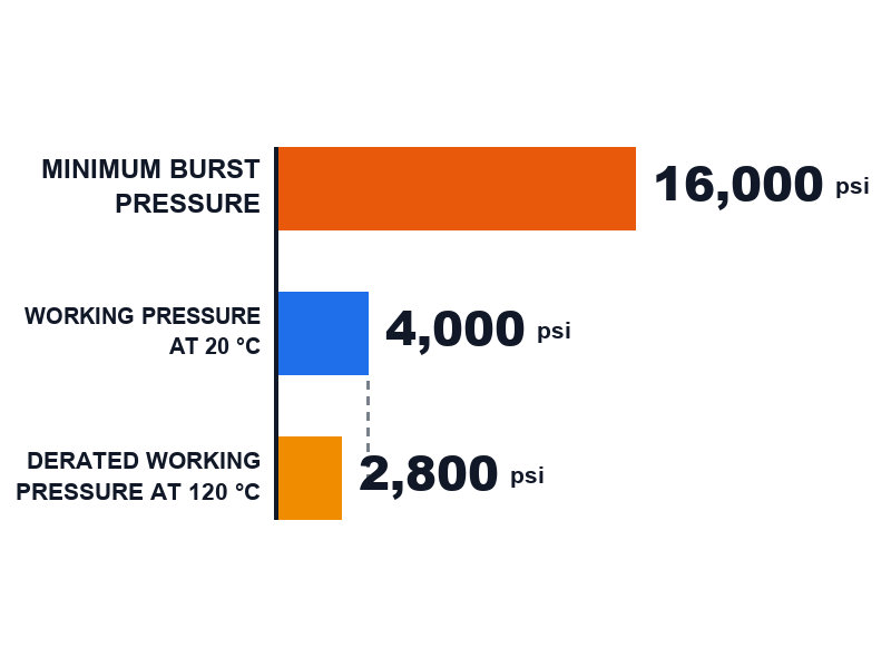
Temperature derating rule of thumb: above a tube compound’s continuous limit, reduce the working pressure by about 1.5 percent for each additional °C. Worked numbers: a nitrile hydraulic hose rated 4,000 psi at a 100 °C continuous limit, run at 120 °C, is 20 °C over that limit. That is 20 × 1.5% = a 30 percent reduction, so its usable working pressure becomes 4,000 × 0.70 = 2,800 psi. Its published minimum burst pressure stays at 16,000 psi, because that figure is quoted at the rated temperature rather than at 120 °C. Source note: the 1.5 percent per °C derating is an industry rule of thumb used across hose suppliers rather than a clause in EN 853 or SAE J517, so confirm the derating for the specific compound on its datasheet.
Low-temperature limits: cold flex, cold bend and why the minimum flex temperature is a separate rating
The pressure rating is quoted at rated temperature, and rated temperature has a floor as well as a ceiling. Below the compound’s low-temperature limit the tube and cover stiffen, and a stiff hose that is flexed or bent concentrates stress in the cover and can crack it. Two mechanisms produce the failure: cold bend damage, where the hose is bent cold and the cover or tube cracks; and cold flex fatigue, where repeated flexing at low temperature starts a crack that later reaches the reinforcement. Neither is visible on a pressure gauge and neither is predicted by the 4:1 ratio.
Two practical points follow. First, the minimum flex temperature a datasheet quotes is a separate rating with its own test method rather than a margin on the working pressure: standard wire-braid constructions are commonly rated to −40 °C, and specialised compounds go lower. That figure belongs to the compound and the standard that governs it, so it cannot be traded against the pressure rating. Read the minimum flex temperature for the compound you order, in the same way you confirm the high-temperature limit. Second, hose that will be installed or routed cold should be warmed or routed to a more generous bend radius until it is back inside its rated range.
I have an oil suction hose rated 10 bar at 20 °C that runs at 120 °C — what is the real rating?
The rating you may use is the derated figure, not the catalogue figure. Using the same rule of thumb as above, 20 °C above the usual 100 °C continuous limit for standard compounds is 20 × 1.5% = a 30 percent reduction, so a 10 bar rating becomes 10 × 0.70 = 7 bar of usable working pressure. Two checks come before you accept that number: confirm the continuous temperature limit of the specific compound on the datasheet, because a compound rated to 120 °C continuous needs no derating at all; and confirm that the burst figure behind the rating still satisfies the factor the standard applies to that product family. If the hose was selected on its catalogue rating for a 120 °C duty, it is running outside its rated conditions.
Can I derate a 4,000 psi hose for 120 °C fluid instead of buying a high-temperature hose?
Derating tells you whether the hose is still inside its rating; it does not upgrade the hose. Applying the same arithmetic, a 4,000 psi hose rated to 100 °C with a 20 °C overage becomes a 2,800 psi hose, so it can serve a circuit that needs no more than 2,800 psi of continuous working pressure. What derating cannot do is restore the cover, the adhesion or the reinforcement if the hose has already been run hot, and it cannot turn a 2,800 psi result into a 4,000 psi one. If the circuit needs the original rating at 120 °C, the correct answer is a compound rated to that temperature rather than a larger derating calculation.
Why impulse life and burst pressure are different questions
Burst pressure answers “how much static pressure until it breaks”; impulse life answers “how many times can it be cycled before it breaks”. A hose can pass a burst test impressively and still fail early in a high-cycle circuit, because fatigue accumulates independently of peak pressure. SAE J517 sets a minimum impulse requirement for its hose types, and the higher grades of the ISO 18752 family are defined specifically by cycle count at the impulse test pressure rather than by construction. If your machine cycles several times a minute, impulse life, not burst margin, is the number that will decide how long the hose lasts.
Two of the factors in the table above deserve their own reading, because they are the ones most often mis-set at the specification stage rather than in service. Bending a hose tighter than its rated minimum puts a permanent stress concentration into the reinforcement, and our hydraulic hose bend radius guide covers how to route around that limit. Choosing the wrong inner tube compound attacks the hose from the inside, where no pressure rating protects you, and our fluid compatibility chart for NBR, EPDM and FKM tubes shows which compound suits which fluid.
11. What Does the Layline Tell You: Reading Working Pressure and Burst Pressure on a Hose
Everything above assumes you can identify the hose in front of you, and that information is printed on the cover in a single line called the layline. Decoding it matters, because a partially illegible layline is itself a rejection criterion.
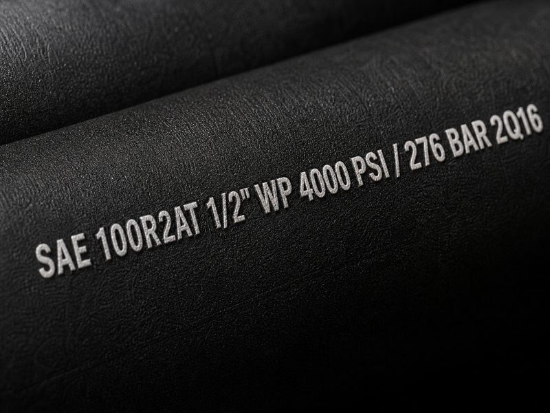
A representative layline reads:
SAE 100R2AT 1/2" WP 4000 PSI / 276 BAR 2Q16| Element | Significado |
|---|---|
| SAE 100R2AT | The construction standard — two steel wire braids with a thin cover, rated to the SAE J517 working pressures for that type |
| 1/2″ | Nominal inside diameter — dash size -08 in this case |
| WP 4000 PSI / 276 BAR | Maximum working pressure — the continuous limit, in both unit systems |
| 2Q16 | Manufacturer’s date or lot code, used for traceability and to establish the hose’s age |
The layline prints the working pressure only. Minimum burst pressure is a verification figure held in the manufacturer’s test documentation rather than an operating limit printed on the hose, which is why it is absent from the cover. An operator who has found the burst pressure on a datasheet has found the wrong number to use for daily operation.
SAE 100R2, 100R2AT and R2AT: Which Designation Are You Buying?
The safe rule is to read the values against the designation printed on the document in front of you. SAE 100R2AT is an SAE J517 type designation for a hose built with two steel wire braids and a thin outer cover, and the same construction is shortened to 100R2 or R2AT in catalogues and quotations, or described simply as a two-braid hose. Two documents can therefore use different labels and still describe the same construction, and they can also use the same label while quoting values read from a different edition of the standard. Confirm which SAE J517 designation the proof and burst values were read against before you compare one supplier’s figures with another’s, rather than assuming the label settles it.
Why does my hose keep bursting at the fitting if the hose body is rated correctly?
Because the joint is a separate assembly operation, and it carries its own failure modes. The published pressure rating describes the hose as a construction, not the crimp that terminates it. Four checks close most of that gap:
- Crimp diameter against the assembly specification. The fitting manufacturer publishes a target crimp diameter for each hose and fitting combination, and a crimp outside that window removes margin without any visible sign.
- Correct fitting series for the pressure. A fitting rated below the hose is the limiting component in the assembly, whatever the layline says.
- Insertion depth and skive. Wire braid that does not reach the full insertion depth cannot be gripped by the crimp.
- Proof-test evidence per assembly. A proof test at the value the governing standard requires is the only check that catches a bad crimp before the machine does.
12. How Do I Select a Hose Using the 4:1 Factor?
The working pressure vs burst pressure relationship is only useful if it changes what you order. These five steps turn it into a specification.
- Find the true maximum system pressure, including the relief valve setting rather than the pump’s nominal rating. The relief valve is the highest pressure the system is meant to produce, so it is the floor for your selection.
- Add the transient allowance. For systems with sharp valve closures, reversing loads or cylinders hitting end stops, keep expected spikes within about 125 percent of the hose working pressure. This is a widely used starting allowance in system design rather than a clause in a hose standard, so confirm the value against your machine builder’s specification. A 3,000 psi relief setting with the standard allowance gives a design pressure of 3,000 × 1.25 = 3,750 psi.
- Select a hose whose working pressure clears the requirement with margin, then confirm its minimum burst pressure is at least four times that working pressure. Do this at the dash size you intend to buy rather than at a smaller size, because the rating falls with bore.
- Check the four secondary limits before ordering: fluid and ambient temperature, minimum bend radius against your routing, fluid compatibility with the tube compound, and flow velocity for the bore you chose.
- Require proof-test documentation for the assembly. Ask the supplier which proof pressure they use, confirm it matches the product’s governing standard, and ask for the burst test data for the production lot.
I am replacing the return line on a 3,000 psi hydraulic press — what working pressure do I need?
A minimum of 3,750 psi, which means a hose rated 4,000 psi in the bore you are installing. The calculation is the relief setting plus the transient allowance: 3,000 × 1.25 = 3,750 psi. Two figures follow from that: the hose’s working pressure must be at least 3,750 psi, and its minimum burst pressure floor is 3,750 × 4 = 15,000 psi. In practice a 4,000 psi rated hose clears both, and its minimum burst floor is 4,000 × 4 = 16,000 psi. A 2,500 psi hose would not clear the relief setting at all, whatever its burst figure.
My machine cycles 40 times a minute at 2,500 psi — is a 4:1 hose enough, or do I need a spiral?
At that cycle rate, impulse life is the limiting specification rather than the burst margin. Forty cycles a minute is roughly 2,400 cycles an hour, so a hose can see millions of pressure cycles over a normal service interval. A 4:1 burst ratio is still the requirement, and it is not the number that decides how long the hose lasts. Two questions to put to the supplier: what impulse life is published for the construction at the impulse test pressure, and how does that figure change between a braid and a spiral construction at your bore. If the impulse data shows marginal life at your cycle count, moving to a spiral construction adds fatigue resistance, while adding pressure margin does not.
If your selection process needs to be auditable, which it does on any machine with people near it, a structured checklist beats memory. The STAMPED method covers the same ground in a fixed sequence and is what our own application engineers use when quoting.
13. What Are the Most Common Myths About the 4:1 Safety Factor?
Five statements come up repeatedly in specification meetings, and each one misreads the same rule. They are worth answering individually, because each leads to a different ordering mistake.
Myth: I can run the hose up to its burst pressure for short periods
The safety factor exists precisely because short periods of overpressure are what damage the reinforcement. Operating limit: continuous pressure must stay at or below the rated working pressure at all times, at the rated temperature and within the rated bend radius. The 4:1 gap is not a reserve for peak demand, and a hose run above its rating is outside the design basis that produced the figure.
Myth: a hose with a higher working pressure is always the safer choice
Not if the higher rating arrives with constraints your installation cannot meet. A higher rating can bring a larger minimum bend radius your routing cannot accommodate, or a stiffer construction that flexes badly at the machine’s pivot points. An over-specified hose that is kinked in service is less safe than a correctly specified one, which is why bend radius is checked before price on every line of a specification.
Myth: the proof test pressure is the pressure I can operate at
Proof pressure is a production quality gate, not a rating. It is a test the assembly must survive once, and the assembly then enters service undamaged. Continuous operation is governed by the working pressure, and the burst test that verifies the margin behind it is a separate destructive test on a separate sample.
Myth: hydraulic hose burst pressure is a fixed figure
It is a guaranteed minimum measured at rated temperature, and real samples usually exceed it. Designing on the assumption that they will is how people get injured, because the guaranteed minimum is the only figure every unit in the lot is held to. A single high laboratory result raises no rating.
Myth: if the burst pressure is four times the working pressure, the hose is four times safer than its rating suggests
The 4:1 margin is consumed by spikes, cycling, temperature and ageing rather than held in reserve. It is a buffer for normal service, not spare capacity for misuse. That is also why the margin narrows whenever the hose operates outside its rated temperature or bend radius, as Section 10 sets out.
14. Proof, Burst and Impulse Verification at HENGHUA
Everything in this guide is applied daily on our own production line, and the test programme described below is how we document the ratings we publish. Two different sets of numbers sit behind every rating we quote, and keeping them apart matters. The pressure ratings in Tables 5 to 7 are the published standard values a hose is specified against. The test data behind them — proof test records, lot burst results and impulse performance — comes from our own test bench, and this section sets out what we test and how.
Proof testing
Every hose assembly we ship is proof-tested before it leaves the factory, and the value used depends on the product rather than on a single company-wide number. Oil suction and discharge hose is proof-tested at 1.5 times working pressure, which is the value the industrial hose standards apply to that family. Hydraulic assemblies are proof-tested to the value their governing standard requires for the construction, which is twice working pressure in the published EN 853 and EN 856 tables.
Burst testing
We burst-test samples from production lots to the ISO 1402 and SAE J343 methods rather than relying on incoming wire certificates. The purpose is to catch the failure mode that certificates cannot show: adhesion loss between the reinforcement layers. A hose can be built from fully compliant wire and still miss its burst target if the layers are not bonded correctly.
Impulse testing
Our impulse testing programme cycles assemblies at 133 percent of working pressure, the impulse test pressure used across the hydraulic hose test methods, and we publish the resulting impulse data alongside the pressure rating. Impulse performance is what separates constructions that share a working pressure, which is why we treat it as part of the specification rather than an optional extra.
What this changes for a buyer
When you ask us for a 4,000 psi hose, ask for these five documents together, because together they make the rating verifiable:
- Presión de trabajo and the standard it is published under.
- Minimum burst pressure with the lot burst test data that backs it.
- Impulse performance at the impulse test pressure.
- Proof test record for the assemblies in the shipment.
- A datasheet that names the governing standard and clause rather than quoting a pressure figure on its own.
A supplier who can give you only the first one is asking you to take the working pressure vs burst pressure relationship on trust.
How do I check a burst test report sent by a new hose supplier?
A valid report states nine fields, and a missing one is the fastest way to tell a real test from a copied figure. Check them in this order:
- Hose type and construction — the SAE J517 type or EN family the sample was built to.
- Dash size and nominal bore, because the rating changes with bore.
- Test standard and method — ISO 1402 or SAE J343, with the pressure rise rate the method specifies.
- Working pressure claimed for the sample tested.
- Measured minimum burst pressure for each sample in the test.
- Sample count, because one sample is not a lot result.
- The ratio between the measured burst figure and the working pressure, which should sit at or above four.
- Lot or date code linking the tested sample to the production batch you are buying.
- Date and signatory, with the laboratory or department the report came from.
If the report shows the working pressure and the burst figure but not the lot code or the sample count, ask again. Those two fields are what connect a test result to the hose that will arrive at your dock.
15. Which Reader Are You? Specification Notes for Four Roles
The same 4:1 rule produces four different jobs, and the checklist depends on which one is yours. Find your role below and use the short list that follows it. These are role-specific views of the five-step selection in Section 12 and the document list in Section 14, so they do not repeat the pressure arithmetic — if you have not read those two sections yet, start there.
If you are an OEM design engineer
Your output is a drawing note, so it has to be self-contained. Specify the construction standard (for example SAE 100R2AT or EN 853 2SN), the dash size, the working pressure at that dash size, and the transient allowance you applied. Record the relief setting that produced the requirement, because the next person to touch the drawing will not re-derive it. Then state the minimum burst pressure floor as working pressure × 4 and hold the supplier to it. Two fields are worth adding even though they are not pressure fields: the minimum bend radius and the continuous temperature limit, since both change the usable rating.
If you are a maintenance planner
Your question is usually whether the hose on the machine still matches the hose on the drawing. Work from the layline: construction type, bore, working pressure and date code. A hose whose layline is illegible is a rejection rather than a judgement call, because none of the four figures can be verified. For replacement scheduling, the two numbers that predict life are the impulse duty of the circuit and the temperature the hose actually sees, not the burst figure. If a hose has failed at the fitting rather than along the body, treat it as an assembly problem and check the crimp before the pressure rating.
If you are in procurement or sourcing
Your leverage is asking for evidence rather than a rating. Require four documents beyond the datasheet itself — the proof test record for the assemblies, the lot burst test data, the impulse performance at the impulse test pressure, and a statement of the working pressure’s governing standard — which together cover the five items listed in Section 14. Ask which proof value applies to the product family, because 1.5× and 2× are both legitimate in different families and a mismatch is a documentation problem you can catch before the shipment. Where a supplier quotes a working pressure with no traceable standard behind it, treat the figure as unverified regardless of how the price compares.
If you are a distributor or reseller
Your customer will ask why two hoses with the same bore and a similar look carry different pressure ratings, and the answer is the construction plus the standard. Explain the working pressure as the continuous limit and the burst pressure as a verification figure the manufacturer holds, never as an operating number. For each stock line, keep the working pressure, the minimum burst pressure and the temperature range on one page, and note which standard governs. That single page answers most technical questions that reach a counter or a customer service inbox, and it prevents a return caused by substituting a 3:1 product into a 4:1 duty.
16. Frequently Asked Questions: Working Pressure vs Burst Pressure
What is the difference between working pressure and burst pressure?
Working pressure is the maximum pressure a hose is designed to carry continuously in normal service. Burst pressure is the pressure at which it ruptures. For hydraulic hose, the minimum burst pressure must be at least four times the working pressure, which is the 4:1 safety factor.
What is the 4:1 safety factor in plain terms?
It is the rule that the working pressure vs burst pressure gap must be a factor of four: a hose rated for a given working pressure must be proven to survive at least four times that pressure before it ruptures. That margin covers pressure spikes, fatigue, temperature and ageing, and it is written into SAE J517, EN 853 and EN 856.
What is a good safety factor for a hydraulic hose?
4:1 is the minimum for hydraulic hose under SAE J517, EN 853 and EN 856, meaning minimum burst pressure at least four times maximum working pressure. Higher factors apply elsewhere: 3:1 is common for low-pressure water hose under 150 psi, and severe-service steam hose can reach 20:1. A factor below 4:1 on a hydraulic hose means the product is not built to the hydraulic hose standards, so confirm which standard the datasheet is quoting before comparing it with another supplier’s.
Why is the safety factor 4:1 and not 2:1?
Because the hydraulic hose safety factor has to absorb pressure spikes, impulse fatigue, temperature effects, ageing and manufacturing variation simultaneously. Hydraulic hose standards such as SAE J517, EN 853 and EN 856 set the minimum burst pressure at four times working pressure to cover all of these at once.
What is the minimum burst pressure of a 4,000 psi hydraulic hose?
The minimum burst pressure is 16,000 psi, equivalent to roughly 1,103 bar. Any hose rated 4,000 psi working pressure that cannot demonstrate at least 16,000 psi minimum burst pressure does not meet the 4:1 requirement.
Is proof pressure the same as burst pressure?
No. Proof pressure is a non-destructive production test that the assembly must survive, commonly twice working pressure for hydraulic hose in the EN 853 and EN 856 tables, and 1.5 times working pressure for many industrial hoses. Burst pressure is a destructive type test that ends in the sample’s failure. The comparison of proof pressure vs burst pressure is therefore a comparison between a quality gate and a destruction limit.
Does every hose use a 4:1 safety factor?
No. The 4:1 factor is standard across the hydraulic hose family under SAE J517, EN 853 and EN 856, and it is the ratio HENGHUA applies to its oil suction and discharge hoses as well. But low-pressure water hose rated under 150 psi commonly uses 3:1, and steam hose in severe service uses a substantially higher factor, up to 20:1 in some products, because stored energy makes a small margin unacceptable.
Why do hydraulic hoses burst even when the working pressure rating looks sufficient?
Four causes dominate: pressure spikes above the steady operating pressure, reinforcement fatigue from high impulse cycle counts, temperature derating above the compound’s continuous limit, and damage or defects at the crimp and fitting. Burst pressure is a static number, so a hose can pass a burst test and still fail early in a high-cycle circuit. Check the impulse rating and the bend radius, not the burst figure alone.
Can I calculate the working pressure from a burst test result?
Yes, if you divide it. A measured minimum burst pressure divided by four gives the highest working pressure the hose may be rated for. A sample bursting at 19,140 psi supports a working pressure of 4,785 psi, which matches the published rating for EN 853 2SN hose in 3/8 in bore.
What happens if I run a hose above its working pressure?
The reinforcement fatigues faster and the hose fails earlier than its rated life. The operating limit is set out in Section 10: continuous pressure at or below the rated working pressure, at the rated temperature and within the rated bend radius. A hose run above its rating sits outside the 4:1 design basis, so the margin is consumed rather than preserved.
Is rated pressure the same as working pressure?
No. Treat them as different questions: working pressure is the continuous operating limit, while rated pressure is whatever limit a particular datasheet happened to quote. The practical test is to ask the supplier to state both the working pressure and the minimum burst pressure — the two figures a standard actually fixes — rather than relying on the word “rated”.
How much does temperature reduce the working pressure?
A widely used industry rule of thumb is to reduce working pressure by about 1.5 percent for every degree Celsius above the compound’s continuous temperature limit. A 4,000 psi hose rated to 100 °C operated at 120 °C should be treated as roughly a 2,800 psi hose. Confirm the limit and the derating for the specific compound on its datasheet.
Does a higher burst pressure always mean a better hose?
Not on its own. Burst pressure is a static number, while service life in a real circuit is usually governed by impulse fatigue, bend radius behaviour, abrasion resistance and the quality of the crimp. A construction with a high burst figure and poor adhesion will still fail early, which is why we publish impulse data alongside every pressure rating.
Final Verdict: Use Working Pressure to Select, Burst Pressure to Verify
The working pressure vs burst pressure distinction comes down to two different jobs. Working pressure is a selection number. It tells you whether the hose is appropriate for your system, and it is the number you compare against your relief valve setting plus your transient allowance. Burst pressure is a verification number. It tells you the margin behind that rating, and under the 4:1 safety factor it must be at least four times the working pressure you selected. For a hydraulic hose pressure rating to be useful in a quotation, it has to arrive with the standard behind it.
Three habits prevent most of the failures we see in the field. Select at the dash size you will actually install, because ratings fall steeply with bore. Check temperature and bend radius before you check price, because neither is negotiable once the pressure rating passes. And ask for the burst and impulse data that proves the rating rather than accepting the pressure figure on its own.
If you are specifying hydraulic or oil hose and want the numbers that back the rating — working pressure, minimum burst pressure and impulse performance, documented for the lot you receive — send us your system pressure, bore size, fluid and duty cycle. Our application engineers will confirm the specification and reply with the datasheet the same business day, and we will include the test data with the sample so you can verify the 4:1 factor on the hose you are actually buying.
About HENGHUA
HENGHUA manufactures hydraulic hoses, oil hoses and hose assemblies for equipment builders, distributors and OEM brands worldwide. Our range covers the full SAE 100 series — including SAE 100R1 single braid, 100R2 double braid, 100R12 four-spiral and 100R13 / 100R15 high-pressure spiral constructions — alongside the EN 853 1SN and 2SN and EN 856 4SP and 4SH families, from 1/4 in to 2 in bore. Our oil hose range covers oil suction and discharge, oil transfer and petroleum delivery duty to EN 1765 and DIN 20023.
Because we control the whole process in-house — compound mixing, wire braiding and spiralling, extrusion, crimping and pressure testing — the ratings we quote are backed by lot test data rather than by a catalogue figure alone. Assemblies are proof-tested to the value their governing standard requires for the construction, samples from production lots are burst-tested to the ISO 1402 and SAE J343 methods, and impulse performance is verified at 133 percent of working pressure. Test reports and lot data are available on request.
If you are sourcing hoses and need the pressure ratings documented rather than asserted, talk to our application engineers with your working pressure, bore size, fluid and duty cycle. We will confirm the specification, send the test data with the sample, and quote factory-direct with short lead times on bulk orders.
About this guide
Author: HENGHUA Application Engineering Team. This guide is written and maintained by the application engineers who specify hydraulic and industrial hose assemblies for construction, mining and oil transfer equipment, and who run the hose testing programme referenced in Section 14.
Reviewed by: HENGHUA Engineering Team, Hydraulic Hose Division.
Updated: retitled the testing section to match the verification work it describes, removed a duplicate failure-mechanism list, aligned the document-count wording between Sections 14 and 15, and differentiated two FAQ answers that had repeated their source definitions. Earlier revisions the same day added the pressure terminology map, the two-column minimum burst table, the low-temperature limits section, the supplier test report checklist, the standard locators and the related-guides list.
This guide is a 16-section engineering guide written for engineers, maintenance planners and procurement teams specifying hose by working pressure. Figures quoted are the published values from the standards this guide names in Section 7, and should be confirmed against the manufacturer’s datasheet for the specific product and size being ordered.
 English
  Spanish
  Portuguese
  French
  German
  Arabic
  Russian
  Indonesian
  Japanese
  Korean