
Precast concrete curing with steam is atmospheric-pressure curing: saturated steam raises chamber temperature and holds humidity near 100%, and the hose is the hardware that carries it from the header to the bed. This page covers that hardware, from manifold layout and drop hoses to bore sizing, insulation, drainage and the control points an operator watches.
The short answer for most beds: size each drop hose to its manifold take-off, insulate the run, drain every low point, and hold the chamber under the 150 °F (65 °C) default ceiling. Three decisions carry that answer: how steam reaches each casting, how much each drop hose must pass, and how condensate leaves the circuit. All three are visible on the layout before a hose is ordered, and all three are cheaper to correct on paper than after the beds are poured.
The guide describes the hardware of a precast steam curing installation rather than the chemistry of cement hydration. Where the underlying principle matters, it links to the article that owns that subject.
All pressures are gauge pressures at the hose outlet; saturated-steam temperatures are the saturation temperatures at those pressures. About 18 min read.

Figure 1. A manifold and drop-hose distribution point serving a precast casting bed.
What a Precast Concrete Curing System Has to Deliver
A steam installation in a precast plant has one job: deliver heat to the concrete without drying it out. Saturated steam does both at once, because it condenses on the cooler surface and gives up its latent heat there. The hose is the last link in that chain and the easiest link to get wrong.
The hardware between the boiler and the casting is short and simple. A header runs down the bay, manifolds branch from it, and drop hoses carry steam to individual beds or into an enclosure. Each part of that chain is a precast concrete curing component with its own duty, and a concrete curing hose is only as good as the layout around it.
The installation has to satisfy five requirements at the same time. It must supply steam at a controlled pressure, distribute it evenly, hold humidity near 100%, remove condensate, and stay controllable. A weakness in any one of them shows up as a cold corner, a wet floor or a cracked edge.
Table 1. What an atmospheric steam installation must deliver and the hardware that delivers it.
| Requirement | Hardware that meets it | Symptom when it is neglected |
|---|---|---|
| Heat input | Boiler or steam generator, main header, manifold | A starved far end of the bay and a slow ramp |
| Even distribution | Manifold branches, isolation valves, drop hoses | Cold spots and uneven strength gain between beds |
| Humidity retention | Enclosure or chamber with steam admitted inside it | Surface drying and early shrinkage cracking |
| Condensate removal | Drip legs, steam traps, low-point drains | Water hammer, wet steam and uneven heating |
| Control | Temperature sensors, modulating valve, cycle timer | Ramp outside the safe band and wasted cycle time |
Most of those requirements are settled by the plant layout rather than by the boiler. The layout items are where hose selection starts to matter. Valve placement, drain points and drop lengths decide the pressure and the steam quality each hose actually sees.
Layout: Header, Manifold and Drop Hoses in the Steam Curing Chamber
A steam curing chamber is an enclosure that holds the casting at near 100% relative humidity while steam is admitted inside it. The layout around it decides whether that steam arrives evenly: a header sized for the total flow of every manifold it feeds, not for the largest single branch. Running a small header down a long bay guarantees a pressure drop along the run.
The manifold is the distribution point. It turns one header branch into several drop connections and gives each of them a valve, so a single failed drop hose can be isolated without stopping the bay. Mount it above the working area, where condensate cannot pool inside the branch.
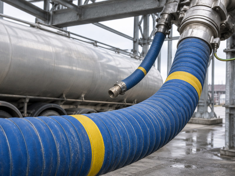
Drop hoses then carry steam from the manifold to the inlet of the steam curing chamber, or to the space under a curing cover. Keep each drop as short as the geometry allows and support it so it never rests on fresh concrete. A drop hose lying in a puddle of condensate will not last a season.
Route drops so that they can be drained and disconnected without a ladder. Steam admitted from above falls and spreads; steam admitted at floor level can short-circuit along a wall. Both patterns are common in precast yards, and both need a drain at the lowest point.
Confirm the following on the layout drawing before any hose is ordered:
- Header diameter against total manifold flow
- Manifold height above the casting bed
- Number and spacing of drop connections
- Valve position for each drop, reachable from the floor
- Lowest point of every branch, with a drain
- Support points that keep hose off the concrete

Figure 2. Drop hoses hanging from a manifold, each on its own isolation valve.
Manifold length matters more than most layouts admit. A long manifold with widely spaced take-offs runs cooler at the far end, because the steam has further to travel and more surface to lose heat through. Where the bay is very long, two smaller manifolds usually beat one large one.
Choosing the Curing Hose Size
Curing hose size sets the steam velocity inside the line, and velocity drives both heat delivery and pressure loss. An undersized drop passes less steam than the branch feeding it, so the chamber sees a pressure drop and a slow ramp. An oversized drop is heavy, awkward to handle and slow to warm through.
A concrete curing hose is specified by inside diameter, working pressure class and end connection. Hose length matters as well, because pressure loss accumulates along the run rather than at the fittings alone. The right curing hose size keeps the drop from becoming the narrowest point in the branch. On most chambers that means matching the manifold take-off instead of stepping down for convenience.
That relationship fixes the number people ask about. If the manifold take-off is 25 mm, the drop is 25 mm. Stepping down to a lighter bore turns the drop into the limiting orifice of the branch, and no valve opening recovers the flow.
The reference for bore against flow and length is the same one used on any steam line. If the drop is long, or if the take-off is already marginal, move up one size rather than accept a soft ramp. The hose size selection guide sets out the arithmetic for a range of bores and run lengths.
Table 2. Drop-hose bore against typical duty in a precast curing installation; each band is a relationship to the manifold take-off, not an absolute size.
| Drop duty | Practical bore band | What drives the choice |
|---|---|---|
| Short drop to a single bed | Small bore, matched to the take-off | Handling weight and condensate during warm-up |
| Long drop to a far bay | One size above the take-off | Pressure loss along the hose run |
| Manifold-to-chamber trunk | Largest practical bore | Total flow for the whole enclosure |
| Cold-weather duty | Same bore, insulated | Heat loss, not flow capacity |
Bore is not a place to economize. The pressure drop in an undersized drop hose is paid for every cycle, in a longer ramp and more steam at the boiler. Insulation cannot compensate for a bore that is simply too small.
Concrete Steam Curing Temperature and the Hose It Implies
Precast steam curing runs at atmospheric pressure with saturated steam, and chamber temperatures commonly sit between 104 °F and 158 °F (40 °C and 70 °C). Pressure and temperature are not independent variables: the working pressure of the steam fixes its saturation temperature. A hose chosen on temperature alone, without regard to the pressure that produces that temperature, is a selection error.
The upper limit of concrete steam curing temperature is set by the concrete rather than by the hose. The National Precast Concrete Association’s QC Manual states that ambient curing temperature should not exceed 150 °F (65 °C) unless measures to prevent delayed ettringite formation are taken. That principle belongs to the article on why steam cures precast concrete; here it is a control limit the hardware has to respect.
The 150 °F (65 °C) line is the default ceiling, not a target. A chamber held at 158 °F (70 °C) is running under DEF measures, so it is a different regime rather than the same one run hotter.
Hose rating then follows from the steam condition. ISO 6134 Type 1 covers a maximum working pressure of 6 bar, and Type 2 covers 18 bar. Saturated steam at 6 bar is about 165 °C, and the Type 2 envelope corresponds to a saturated-steam temperature of 210 °C. A perforated cover vents steam that permeates the tube instead of letting it lift the cover into blisters.
Most precast duty sits far below those ceilings. A chamber held at 60 °C needs nothing like a Type 2 assembly, yet the hose still has to survive repeated cycling and constant condensate. The EPDM saturated steam hose guide covers the compound and the layer anatomy behind those ratings.
Table 3. Stages of an atmospheric curing regime, the chamber temperature at each stage and the hose consideration.
| Stage | Typical chamber temperature | Typical condition | Hose consideration |
|---|---|---|---|
| Preset (initial delay) | Ambient | Steam off, cover in place | Condensate drains back to the trap, hose stays unpressurized |
| Ramp | Ambient rising to the set point | Rise limited to about 40 °F/h (22 °C/h) | Highest flow demand and the most condensate in the line |
| Hold (soak) | 104–158 °F (40–70 °C), below 150 °F (65 °C) unless DEF measures are in use | Target temperature, near 100% relative humidity | Steady flow; valve partly open to hold the set point |
| Cooling | Set point falling toward ambient | Controlled, steam shut off | Hose returns to ambient; water hammer risk if it is undrained |
Temperature margin is a design choice, not a target to consume. Running a hose at the very top of its pressure class leaves nothing for a supply upset. A modest margin costs little and removes the pressure and temperature rating question from the maintenance list.
Insulation, Condensate and Drainage in a Steam Curing System
Insulation protects heat the plant has already paid for. An uninsulated drop hose loses heat along its length, so steam arrives wet and the ramp takes longer. Insulate the header and manifold first, because they are the longest static runs, then the drops.
Every unit of heat lost inside a steam curing system becomes condensate somewhere downstream. Condensate in a drop hose reduces the flow area, adds weight and travels as a slug when the valve opens. That slug is what damages couplings and whips hoses off their supports.
Drainage is therefore a design item, not a housekeeping item. Fit a drip leg and trap at the end of each header run and at the bottom of each manifold branch. Slope branch lines back toward the trap so water cannot stand in a horizontal section.
Steam traps need a strainer ahead of them and a bypass for maintenance. Where a trap cannot be fitted, a manual drain valve opened at the start of each cycle is the practical fallback. Opening it fully during warm-up is far better than leaving it cracked for the whole shift.
Check the drainage path at each of these points during commissioning:
- End of every header run
- Bottom of every manifold branch
- Low point of each drop hose
- Floor drain inside the enclosure
- Trap discharge, visible and unblocked

Figure 3. A drip leg and steam trap at the lowest point of an insulated manifold.
Insulation and drainage work together, and neither substitutes for the other. Insulation slows heat loss and reduces how much condensate forms. Drainage removes whatever forms anyway. A plant that insulates everything but drains nothing simply moves the water problem to a colder part of the line.
Control Points for a Steam Curing Chamber
Five set points control a chamber: ramp rate, hold temperature, humidity, cooling slope and condensate level. Each has a hardware consequence, and each can be read off Table 4. All five depend on steam arriving on demand, so a valve that cannot modulate overshoots the set point and then undershoots it. Ramp rate, humidity and cooling carry the operating risk; hold temperature and condensate level follow from the valve setting and the traps.
Each control point below is really a flow decision. Ramp rate is the most cited number in the regime, because it is where the concrete is most exposed. A rise faster than about 40 °F/h (22 °C/h) can thermally shock the concrete and crack it. A rise slower than about 20 °F/h (11 °C/h) wastes the benefit accelerated curing is bought for.
Humidity is the second control point and the easiest one to lose. The chamber is held near 100% relative humidity because the point of steam is to deliver heat without drying the concrete. If the enclosure leaks along the top, steam escapes and cool air is drawn in at the bottom.
Cooling is the third control point and it is usually the least controlled. The hold ends, the valve closes and the cover comes off. A controlled cooling slope costs little and protects the corners. Recording ramp, hold and cooling lets the next cycle be compared with the last.
Table 4. Control points in a precast curing enclosure, their targets and the hardware behind them.
| Control point | Target or condition | Hardware that holds it |
|---|---|---|
| Ramp rate | Between about 20 and 40 °F/h (11 to 22 °C/h) | Modulating valve, header capacity, drop-hose bore |
| Hold temperature | Set point below 150 °F (65 °C) without further measures | Sensor placement, valve authority, manifold balance |
| Humidity | Near 100% relative humidity | Enclosure seals, steam admitted inside the volume |
| Cooling slope | Controlled, no sudden opening | Ventilation control, cycle timer, operator procedure |
| Condensate level | No standing water in branches or hoses | Traps, drip legs, low-point drains |
Read Table 4 row by row: the target takes the form that suits it, whether a band, a ceiling, a percentage, a procedure or a condition, and each row stands on its own.
Control and hardware cannot be separated. A ramp that is too fast is often an oversized valve or a missing preset, not a stubborn operator. A hold that will not settle is usually an unbalanced manifold or a sensor sitting in a steam jet.
Precast Concrete Curing in Cold Weather
Cold weather does not change the curing limits; it changes how much heat the hardware has to hold. A cold bed absorbs more heat before its surface temperature moves, so the preset lengthens and the ramp takes longer. The hose also sees more condensate, because cold surrounding air takes more heat from the line.
The practical response is insulation and drainage capacity rather than more pressure. Extra pressure pushes more steam, but it also pushes more condensate and raises the stress at the couplings. Insulating the drops and enclosing the bed pays back faster than opening the valve further.
Cold weather also exposes weaknesses in the layout. A drop hose that sags into a puddle can freeze between shifts. A frozen trap or a blocked drip leg is a burst fitting waiting to happen. Drain the circuit at the end of the shift and support every drop clear of standing water.
A precast concrete curing regime written for summer will not hold through a hard winter without adjustment. Lengthen the preset, insulate the drops and check every drain before the first freeze. The concrete does not change; the heat loss around it does.
Specifying Hose for Precast Concrete Curing
A curing hose specification has five line items, and Table 5 lists them in the order to write them. A specification that names only a bore and a length will be filled with whatever is cheapest. State the steam condition, the expected cycles, the end connections and the routing, then ask for the marking and the test record on every assembly.
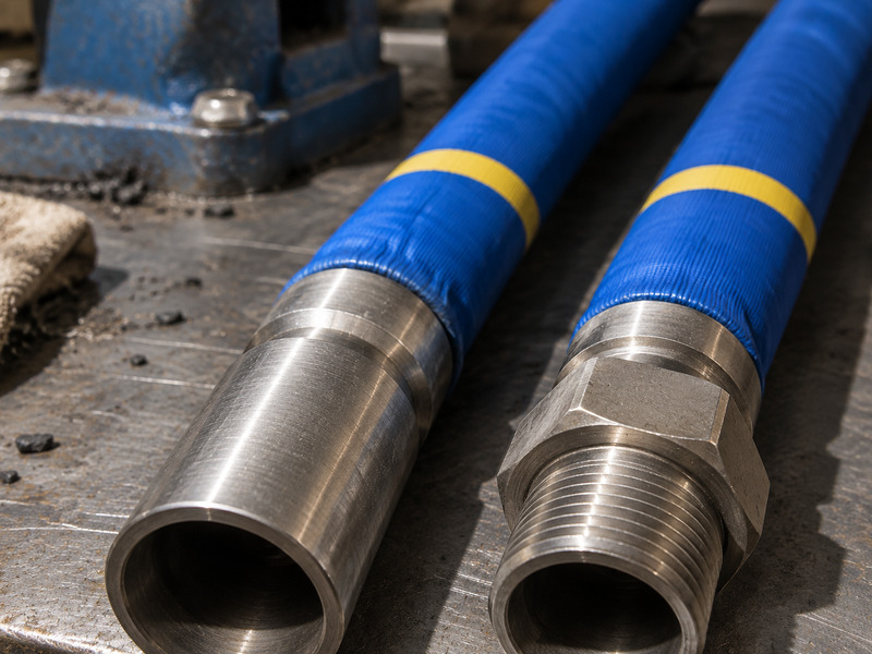
For a curing hose assembly, the end connection is where most field failures begin. Crimped or swaged ferrules, bolted safety clamps, flanged ends and cam and groove couplings are all in common use. The right choice follows the manifold take-off and the way the hose is handled, not habit.
Every HENGHUA steam hose assembly is hydrostatically tested to its rated working pressure before shipment and marked with its size, working pressure and identification code. That marking is what makes a later inspection possible. Without it, an assembly on the rack cannot be identified against the specification it was bought for.
A shorter specification route is to select from the steam hose collection and then confirm the duty. The same logic applies where a plant moves dry material as well as steam, which is why many yards also specify from the concrete hose range and the cement hose range.
Table 5. Specification line items for a curing hose assembly and what to state for each.
| Line item | Was ist anzugeben? | Why it matters |
|---|---|---|
| Bore and length | Inside diameter and ordered length | Sets velocity, pressure loss and handling weight |
| Pressure class | Rated working pressure above the duty pressure | Fixes the saturated-steam temperature the hose can carry |
| Cover class | Oil-resistant cover with perforations | Vents permeating steam instead of blistering the cover |
| End connections | Ferrules, safety clamps, flanges or cam and groove | Determines how the drop is made off and remade |
| Marking and records | Size, working pressure and identification code | Makes later inspection and replacement traceable |
An inspection routine belongs in the same document as the specification. A drop hose that carries steam into a chamber every day for years will not fail gracefully, and the steam hose inspection program is what catches the pinhole before it becomes a burn. Where the hose is replaced, replace the drain and the support at the same time.
Precast Concrete Curing FAQs
What is a typical concrete steam curing temperature?
Precast plants usually run chamber temperatures between 104 °F and 158 °F (40 °C and 70 °C), which is atmospheric-pressure curing with saturated steam. The National Precast Concrete Association’s QC Manual states that ambient curing temperature should not exceed 150 °F (65 °C) unless measures to prevent delayed ettringite formation are taken. Most yards hold the soak below that figure and control the ramp rate instead.
How long does a precast steam curing cycle take?
A cycle has four stages: an initial preset delay, a ramp, a hold or soak at the target temperature, then controlled cooling. The hold is usually the longest stage and the ramp is usually the most tightly controlled. Total time depends on section thickness and on yard conditions, so write a regime for each product rather than copying one from another plant.
Does every precast plant need a steam curing chamber?
No. Smaller yards often cure under an insulated cover with steam admitted underneath, which holds humidity without a fixed structure. A purpose-built enclosure gives finer control of temperature and humidity and is easier to instrument. The hose requirements are similar either way, because the drop still has to reach the casting and drain its condensate somewhere.
What size curing hose should feed a chamber drop?
Match the manifold take-off first, then move up one size if the drop is long. An undersized drop becomes the narrowest point in the branch, so the enclosure sees a pressure drop and the ramp slows. An oversized drop is heavy, awkward and slow to warm. Check bore against flow and length before ordering.
Can a standard EPDM steam hose be used in a precast steam curing system?
Yes, provided the assembly is rated for the pressure and temperature the duty actually produces and the cover is perforated. Precast duty sits well inside the ISO 6134 Type 1 envelope, where the maximum working pressure is 6 bar and saturated steam is about 165 °C. Confirm the end connections and the marking before the hose enters service.
How do I stop condensate from collecting in drop hoses?
Fit a drain at the lowest point, and let the hose hang so water runs to it rather than standing in a sag. Support each drop clear of the floor, and open the drain during warm-up, when condensate production is highest. Insulating the drop reduces heat loss on the way to the enclosure and cuts condensate at the source.
Why does the chamber temperature overshoot at the start of a cycle?
Overshoot usually means steam was admitted too early or the valve opened too far. A preset delay lets the concrete warm gradually before full steam flow begins. A modulating valve holds the ramp between about 20 and 40 °F/h (11 to 22 °C/h), the band that avoids thermal shock and cracking. Check the sensor position as well.
How often should steam hoses be inspected in a precast plant?
Daily duty on a casting bed justifies a visual check every shift: cover damage, coupling tightness, chafing at supports and damp insulation. A recorded inspection at a fixed interval catches the slow changes a daily glance misses. A hose showing a soft spot, a blister or a weeping coupling should leave service rather than be patched.
What steam pressure does a precast curing installation need?
Much less than a process line or a tire press. Precast curing is atmospheric, so pressure only has to overcome the drop through the header, manifold and drop hoses at the flow the ramp demands. Low-pressure supply is normal, and the hose still needs a rated working pressure above the duty pressure with margin.
What happens if the enclosure is opened too early?
The casting cools faster than the regime intends, and surface and core then shrink at different rates. That difference is where cracking starts, particularly at corners and thin sections. Keep the cooling slope controlled, and let the concrete reach a safe temperature before the cover comes off. On the hose side, the valve closes and the drains stay open.
Final Verdict: Precast Concrete Curing Hose Practice
Precast concrete curing rewards well-drained, correctly sized hardware far more than it rewards a larger boiler. Get the header and manifold right, size the drops for flow, insulate them, and drain every low point. The rest is discipline, which is cheaper than a new generator.
The common failures are almost never the hose itself. Condensate left standing in a branch, a drop resting on fresh concrete and a manifold with no isolation valve cause most of the trouble. Each of those is a layout decision that can still be corrected.
Work through this list before the next pour:
- Confirm header and manifold flow against the total demand
- Check that every drop hose matches its take-off
- Insulate the header, manifold and long drops
- Verify a drain at every low point
- Set the ramp, hold and cooling limits in writing
- Record the marking of every hose in service
HENGHUA manufactures steam hoses, steam hose assemblies, industrial hoses and hose fittings, supplying distributors, EPC contractors and OEM brands worldwide. The steam hose range uses an EPDM tube with textile or steel-wire reinforcement and a perforated, oil-resistant cover. Bore sizes and pressure classes cover the ISO 6134 Type 1 and Type 2 envelopes, and a high-temperature grade is rated to 230 °C. Assemblies are terminated with bolted safety clamps, crimped or swaged ferrules, flanged ends and cam and groove couplings in carbon steel, stainless steel and brass.
Send the duty pressure, the bore and the routing, and the engineering team will confirm the class, the bore and the drainage details for the quote and samples request. Commercial terms include factory-direct pricing, short lead times for bulk orders, private labeling, custom packaging, OEM and ODM branding, and warranty support.
About the author. This guide was prepared by the HENGHUA engineering and test team, which designs steam hose assemblies for precast, industrial and process duty and verifies them on the company’s hydrostatic test bench and steam test loop. The team works from installation reviews and assembly records on the steam-hose line, and revises these notes when field practice changes.


 English
 Spanish
 Portuguese
 French
 German
 Arabic
 Russian
 Indonesian
 Japanese
 Korean