
Composite hose sizing is a two-step decision. The bore comes from the flow rate and the time the transfer is allowed to take, then the pressure drop through that bore is checked against the head the pump can actually deliver. Get the order wrong and the hose either throttles the line or costs more than the duty needs.
This guide covers the arithmetic behind the choice: flow rate against bore, pressure drop per metre, and the point where a 4 inch, 6 inch or 8 inch line stops paying for itself. It also sets out what a bigger bore costs in weight, handling and residual product, and how to write a sizing basis into an enquiry so the quote can be checked rather than trusted.

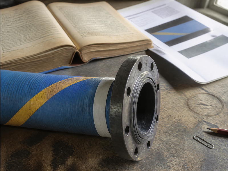
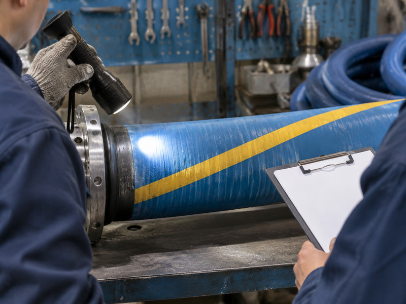
Figure 1. The flange is being offered up to the arm: it is the part that decides whether the string can be rigged by hand.
What Does Composite Hose Sizing Start With?
It starts with a volumetric flow rate and a velocity limit, not with the bore a competitor uses.
The relationship is simple. Flow equals velocity multiplied by the internal cross-section, so for a given flow a larger bore runs at a lower velocity. Velocity is the number that matters, because it sets erosion, static generation and, on the suction side, the risk of cavitation at the pump.
Common practice on liquid transfer lines is 2 to 3 metres per second on the discharge side. Suction lines usually run slower, around 1 to 1.5 metres per second, because a low velocity keeps the pressure at the pump inlet above its vapour pressure. Those figures are practice rather than law, and a viscous product or a short line can justify a different number.
How Do You Turn Flow Rate Into a Bore?
Take the composite hose flow rate in cubic metres per hour and divide by 3,600 to get cubic metres per second. Divide by the velocity in metres per second, and you have the cross-section in square metres. From there, the bore is the square root of four times the area divided by pi.
The table below does that work for the three bores that dominate bulk transfer, at three velocities.
| Nominal bore | Internal diameter | Cross-section | At 1.5 m/s | At 2 m/s | At 3 m/s |
|---|---|---|---|---|---|
| 4 inch | 101.6 mm | 0.0081 m² | 43.8 m³/h | 58.4 m³/h | 87.6 m³/h |
| 6 inch | 152.4 mm | 0.0182 m² | 98.5 m³/h | 131.3 m³/h | 197.0 m³/h |
| 8 inch | 203.2 mm | 0.0324 m² | 175.1 m³/h | 233.5 m³/h | 350.2 m³/h |
Table 1. composite hose flow rate against bore and velocity, calculated from the nominal internal diameter. A 50 mm bore tolerance of 1 to 3 mm changes these figures by a few per cent, not by a category.
Two caveats belong with the table. The figures use nominal bore, and composite hose carries an internal diameter tolerance of 1 mm up to 100 mm and 2 to 3 mm above that. A delivered hose can therefore be slightly wider or narrower than the nominal. And the cross-section is the bore of the hose only, not the bore of the fittings, which is often the tighter of the two.
How Do You Calculate Composite Hose Pressure Drop?
Use the Darcy-Weisbach form. Pressure drop equals the friction factor, multiplied by length over diameter, multiplied by the dynamic pressure of the flow.
In symbols, the drop in pascals is f times L over D times half the density times the velocity squared. Density comes from the product, length from the route including the vertical lift, and the friction factor from the Reynolds number of the flow.
A worked example makes it concrete. A 6 inch hose, 30 metres long, carrying diesel at 830 kilograms per cubic metre and 3 metres per second gives a Reynolds number of about 126,000. The friction factor that follows is near 0.017. The friction loss comes out at roughly 0.12 bar over the 30 metres.
The same calculation at the other two bores, at the same velocity and product, gives about 0.20 bar for the 4 inch and 0.09 bar for the 8 inch.

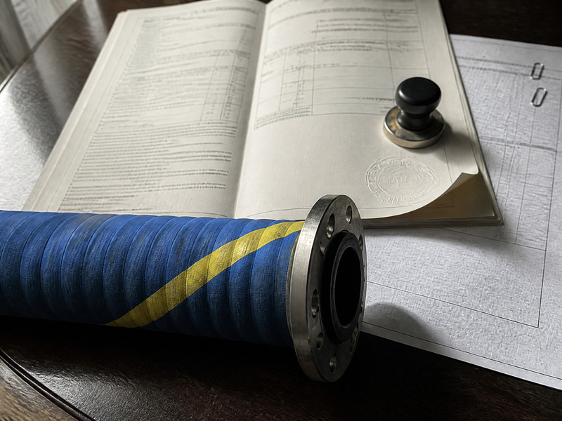
Figure 2. Two people bring the flange up to the manifold by hand, which is the practical limit on bore before a cradle is needed. The pressure the pump has to find for each bore is in the table in this section, not on the drawing.
Treat these as engineering illustrations rather than measured values. A composite hose has a helical bore, which is rougher than a drawn pipe, and every fitting, valve and bend adds a local loss. Add the static head for the vertical lift, and compare the total against the pump curve at the duty flow rather than at its shut-off head.
The number only means something against the pump. Turn the allowable drop into a share of the pump head at the design flow, then check the hose against that share. A drop that eats a large share of the head leaves nothing for the fittings, the valve and the static lift; the share to allow is set from the pump curve, not from a fixed percentage. Where the share is already tight, the answer is a larger bore or a shorter route, not a different lining.
Why Does Bore Dominate the Result?
Because friction loss scales with the fifth power of the diameter at a constant flow. Double the bore and the velocity falls to a quarter, and the loss per metre falls by a factor of 32.
The composite hose flow rate at a fixed pressure drop therefore rises faster than the bore does, which is the other way of reading the same rule. That is why a small change in bore produces a large change in pump pressure. It is also why a line that is marginal on a 4 inch hose is comfortable on a 6 inch one, with the same pump and the same product.
The relationship works in reverse on the suction side. A bore that is too small raises the velocity and drops the pressure at the pump inlet. That pushes the pump towards cavitation, which shows as noise, vibration and a falling flow rate rather than as a clean failure.
How Much Time Does a Bigger Bore Save?
Loading time is cargo volume divided by flow rate, plus a fixed time for connecting, testing and disconnecting that does not change with bore.
| Cargo volume | 4 inch at 2 m/s | 6 inch at 2 m/s | 8 inch at 2 m/s |
|---|---|---|---|
| 200 m³ | 3.4 h | 1.5 h | 0.9 h |
| 500 m³ | 8.6 h | 3.8 h | 2.1 h |
| 1,000 m³ | 17.1 h | 7.6 h | 4.3 h |
Table 2. Loading time against bore for three cargo volumes at 2 metres per second, before connection and disconnect time. The gain is largest between 4 and 6 inch and flattens beyond that.
The last column is where the argument usually ends. Moving from 4 to 6 inch cuts the pumping time by more than half. Moving from 6 to 8 inch cuts it again, but by less, and the fixed time at the berth starts to dominate the total.
A terminal that handles 500 cubic metre parcels several times a week will find the 6 inch case pays for itself in berth occupancy. A terminal that handles one 1,000 cubic metre parcel a month may not recover the handling cost of an 8 inch hose at all.
What Limits a Bigger Bore?
Four things limit a composite hose sizing decision, and none of them appear on a flow chart.
- Weight. Mass rises with bore and with length, and a wet 8 inch hose is a crane job rather than a two-person lift. Handling time eats the pumping gain.
- Residual product. A larger bore holds more product when the line is drained, and that volume is either lost or must be displaced. On a high-value product the loss is a real cost per transfer.
- Rating. The standard type table stops at 14 bar for every type, and the Type 4 bend radius is tabulated only to 100 mm bore. A large bore high temperature line therefore needs a manufacturer agreement rather than a catalogue pick.
- Space. A 150 mm bore hose needs a 575 mm bend radius in Types 1 to 3, and a 200 mm bore needs 800 mm. A berth designed around a 4 inch line may not have the room.
How Does Temperature Change the Sizing?
Viscosity is the field that temperature moves most, and it changes the answer more than most buyers expect. A heavy oil that is turbulent at +40 °C may be laminar at 0 °C, and the friction factor rises as the flow becomes laminar.
The practical approach is to size on the coldest condition the line will see. If the product is heated before transfer, that is the operating temperature. If it is pumped cold, take the ambient minimum for the site and use the viscosity at that point.
Density moves too, but in the opposite direction, so the dynamic pressure falls while the viscosity rises. On most hydrocarbons the viscosity effect dominates below about 20 °C, and the composite hose pressure drop rises sharply for that reason alone.
Temperature also touches the type choice. A product at +120 °C rules out Types 1 to 3 and leaves Type 4, which is rated to +150 °C and tabulated only to 100 mm bore. A hot duty at 6 inch therefore needs a manufacturer agreement, and that conversation should happen before the bore is fixed. Name the temperature the calculation was made at, because a change of product grade can invalidate a bore that was chosen last season.
Is a 6 Inch Composite Hose Usually the Compromise?
For bunkering, chemical parcel transfer and tanker unloading, yes. A 6 inch composite hose carries about 131 cubic metres per hour at 2 metres per second and about 197 at 3. That covers most parcel sizes without the handling penalty of an 8 inch line.
The standard tabulates 150 mm bore with a tolerance of plus or minus 2 mm and a minimum bend radius of 575 mm for Types 1 to 3. Those two figures decide whether the hose fits the route: the tolerance tells you what the fittings must accommodate, and the radius tells you whether the berth layout works.
The bore is also the point where the weight argument changes direction. A 6 inch hose is still a two-person lift on a dry run and a three-person lift when full, which is the practical limit for a crew working a hose string by hand. Above that, the saddle and the crane become part of the sizing decision.
What Goes Wrong in Composite Hose Sizing?
Five errors account for most of the rework we see, and each one is a composite hose sizing fault rather than a hose fault.
- Using the nominal size of a different product family. A 6 inch rubber hose and a composite hose at the same nominal size do not necessarily share an internal diameter.
- Ignoring the fittings. A reduced-bore flange or a camlock with a smaller throat can cost more pressure than the hose itself.
- Sizing on the pump curve at shut-off head rather than at the duty flow.
- Forgetting the static head on a vertical lift, which on a 20 metre rise is about 1.7 bar of diesel.
- Using ambient viscosity for a product that is pumped cold, where the viscosity may be several times higher and the flow regime changes.
Each of these errors survives a quote review, because a bore on a drawing looks correct whether or not the basis behind it was checked. The test is arithmetic. Put the flow, the bore and the pressure drop on one line and see whether the numbers agree with the pump curve. A sizing sheet the buyer cannot reproduce is a preference rather than a calculation.
How Do You Write the Sizing Into an Enquiry?
State the basis, not just the bore. A supplier who receives a flow rate and a product can check the bore; a supplier who receives a bore can only quote it.
| Field | Unit | Why the supplier needs it |
|---|---|---|
| Design flow rate | m³/h | Sets the bore and the velocity |
| Allowable pressure drop | bar | Decides whether the bore passes or fails |
| Product and density at temperature | kg/m³ | Sets the dynamic pressure and the pump duty |
| Viscosity at the lowest temperature | cP | Decides whether the flow is laminar or turbulent |
| Route length and vertical lift | m | Adds friction loss and static head |
| Pump curve or available head | bar at flow | The figure the design must fit inside |
| Working pressure and temperature | bar at °C | Chooses the type in the standard |
| Available bend radius | mm | Checked against the standard table |
Table 3. Fields for a composite hose sizing enquiry. The pump curve is the one item buyers most often leave out, and without it the pressure drop cannot be checked against anything.
With those eight fields, a supplier can size the line and defend the number. Without them, the quote is a guess with a bore attached. The first indication that it was wrong arrives when the pump runs at the top of its curve and the transfer takes twice as long as planned.

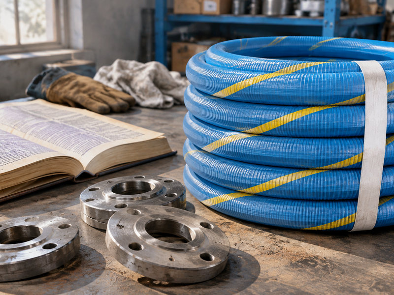
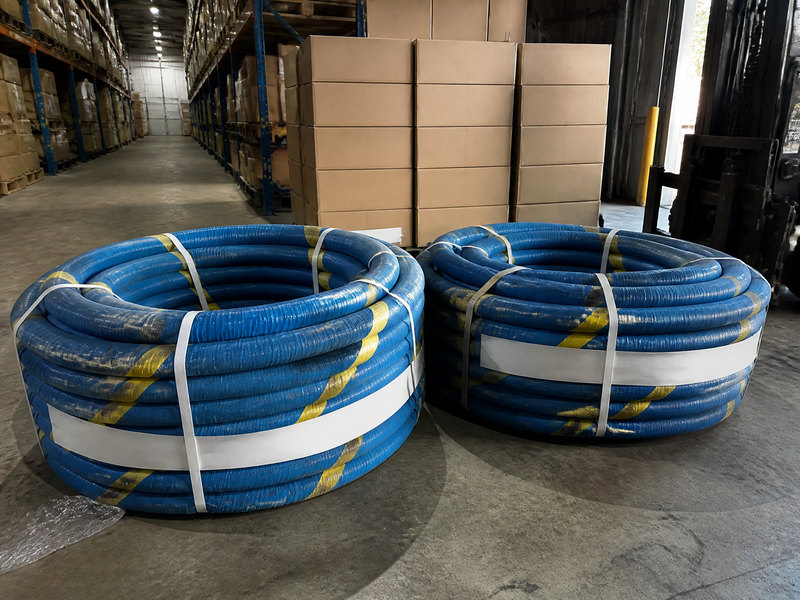
Figure 3. Two large-bore assemblies lying in steel cradles rather than on the ground: past a certain bore the hose stops being something two people carry. The trade between loading time and handling is in the table below, and the flow per bore is in Table 1.
Frequently Asked Questions
How do I choose the bore for a composite hose?
Start from the flow rate and a velocity of 2 to 3 metres per second on the discharge side, then check the resulting pressure drop against the pump curve. The bore that passes both tests is the smallest one that does.
What is a normal composite hose pressure drop?
On a 30 metre line at 3 metres per second with a light petroleum product, expect roughly 0.1 to 0.2 bar depending on bore. Fittings, valves and vertical lift add to that figure and often exceed it.
Does a larger bore always reduce loading time?
A larger bore reduces pumping time but not connection time, and on a short transfer the connection step can be the longer of the two. Beyond 6 inch the fixed time at the berth starts to dominate, so the saving per additional inch falls away quickly.
Can a composite hose be too large?
Yes. Weight, residual product, bend radius and handling effort all rise with bore, and a hose that needs a crane costs more time than the pumping gain returns.
Is a 6 inch composite hose the same as a 150 mm hose?
Effectively yes, since 6 inch is 152.4 mm and the standard tabulates 150 mm bore. The difference is inside the manufacturing tolerance, but the fittings must suit the actual bore delivered.
How does viscosity change the sizing?
A viscous product moves from turbulent to laminar flow, where the friction factor rises and the pressure drop with it. This is the part of composite hose sizing that is most often skipped, and it is the one that produces a line which works in summer and fails in winter. Size on the viscosity at the lowest temperature the line will see.
Does the hose length change the pressure drop?
It changes it in direct proportion, so a 60 metre run has twice the friction loss of a 30 metre run at the same flow. Our bulk loading drop hose guide works through a full terminal layout.
About HENGHUA
HENGHUA offers composite hose and hose assemblies in PTFE, XLPE, polypropylene and UHMWPE linings, a woven fabric reinforcement, and a stainless steel or coated carbon steel helix, in bores from 25 mm to 300 mm. Ends are crimped or flanged, with fixed or floating flanges, and lengths are made to order.
The large bore dock composite hose page lists the sizes and end options, and the full range sits in the composite hose category. composite hose sizing support is part of the enquiry: send the eight fields from Table 3 and we will return a bore, a pressure drop and the type that fits. For the route and support side of a berth installation, our dock hose selection guide covers what the layout has to provide. If the line is a suction duty, the oil suction and discharge guide covers the additional constraints.
 English
 Spanish
 Portuguese
 French
 German
 Arabic
 Russian
 Indonesian
 Japanese
 Korean