
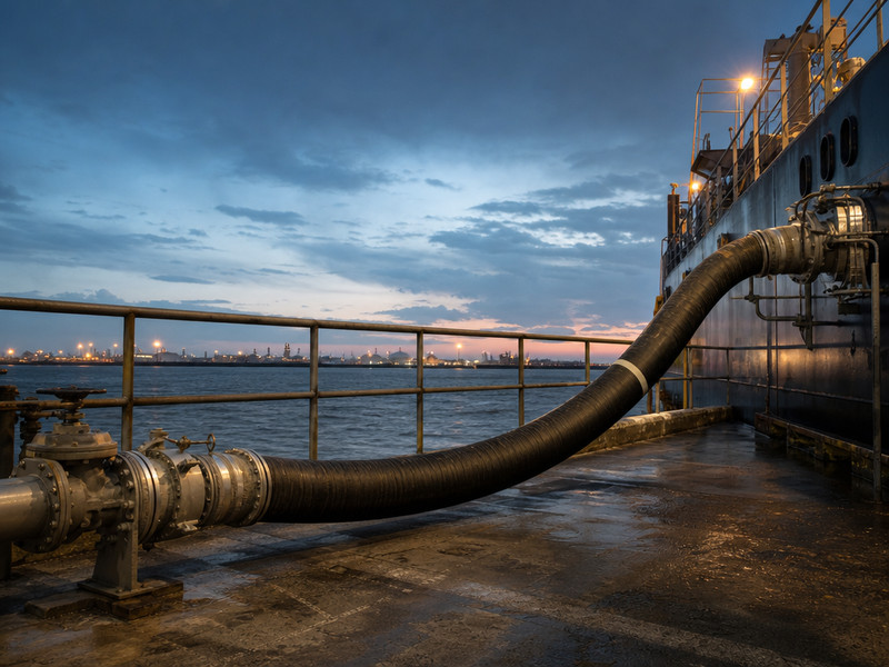
A US facility capable of transferring oil or hazardous material in bulk to or from a vessel has to meet the hose rules in USCG 33 CFR 154. The rules fix three hard numbers. Minimum design burst pressure must be at least 4 × (relief-valve setting plus static head). Maximum allowable working pressure (MAWP) must be greater than that same sum.
The static liquid pressure test must be at least 1.5 × MAWP. This article walks the USCG 33 CFR 154 hose clause set in order, then explains the honest gap between a compliant record and a hose that actually suits the chemical.
1. What USCG 33 CFR 154 covers at a transfer facility
USCG 33 CFR 154 splits into two jobs. The hose assembly design and marking rules sit in 33 CFR 154.500. The recurring test and inspection duties sit in 33 CFR 156.170.
The scope matters more than it looks. The rules attach to the shore side that loads or discharges a vessel. A chemical plant that never loads a vessel is outside this clause set, even if it moves the same product through a hose.
Who the rule reaches
It reaches the facility operator, not the hose maker. The operator owns the design check, the marking check, the test, and the record. A supplier’s data sheet is an input, not a discharge of the duty.
The word “bulk” is the trigger in most inspection conversations. A drum pump on a small quay is not the same thing as a marine loading arm feeding a tanker. Confirm the applicability question before you build a compliance file around the wrong clause set.
What is in scope for a hose
The clause set applies to the transfer hose assembly, meaning the hose and its end connections as one unit. Other industrial hoses on the site sit under other rules.
Turn to the chemical hose category if you are sourcing the tube and cover rather than managing a marine transfer. This article stays with the transfer facility duty.
2. Hose design and marking under USCG 33 CFR 154.500
Section 154.500 is the hose assembly clause. It sets the design burst pressure, the MAWP rule, the service class, the allowed connections, and what the hose must show. Each part carries a condition, so read the condition, not just the number.
33 CFR 154.500(a): minimum design burst pressure
The clause starts from two pressures. Take the relief-valve setting pressure. Where no relief valve is fitted, take the maximum pump pressure. Add the static head pressure of the transfer system at the point where the hose is installed.
The minimum design burst pressure of the assembly must be at least 4 × that sum. The burst rating printed on a data sheet is not the number this clause uses. The static head term is the one people drop.
154.500(b): MAWP above the sum
The MAWP must be greater than that same sum. Read that as a floor, not a target. The clause requires the MAWP to exceed the sum; a hose whose MAWP equals the sum fails it.
Keep both terms in the figure. The relief-valve setting and the static head at the hose location are separate pressures and they add.
154.500(c): service suitability of a nonmetallic hose
Each nonmetallic hose must be usable for oil or hazardous material service. Read this as a service-class check that sits beside the pressure rule, not a restatement of it.
154.500(d): allowed connections
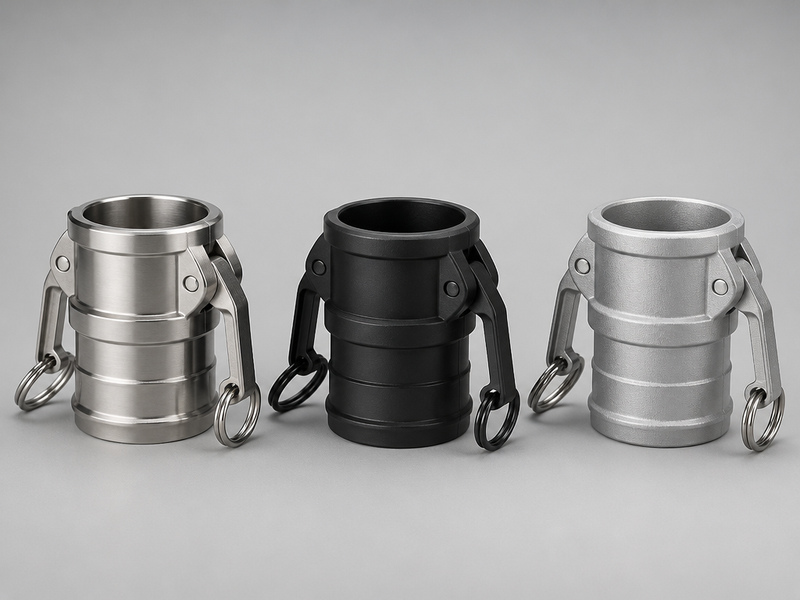
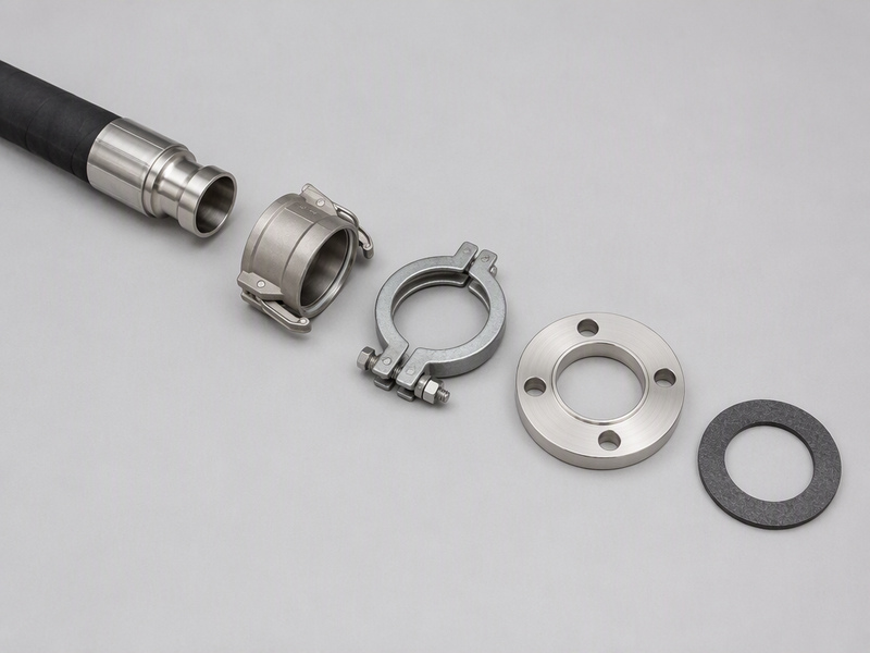
Connections must be one of three kinds. Fully threaded ends. Flanges that meet ANSI B16.5 or B16.24. Quick-disconnect couplings that meet ASTM F1122. A coupling that meets none of those three is outside the clause.
154.500(e): marking the service
Marking must name the service. The choices are the name of each product the hose may carry, or the words OIL SERVICE, or the words HAZMAT SERVICE—SEE LIST. The last option must be followed immediately by a symbol that is keyed to the facility operations manual.
That symbol is the link between the hose and the list of approved products. Without the key, the mark tells an inspector nothing.
154.500(f): marking pressure and dates
The hose also must be marked with the MAWP, the date of manufacture, and the date of the latest test required by 33 CFR 156.170. The last two need not be on the hose itself, provided they are in the vessel or facility hose records and the hose is marked so it can be identified with those records.
Many operators mark an identification code on the hose and keep the dates in the record. That is the practical version of this clause.
154.500(g): what must not be marked
The cover carries the service mark, the MAWP and the identification code, and nothing else. Burst pressure and the hose test pressure must not be marked on the hose; hold both in the hose file. A burst figure on a cover invites someone to read it as an operating limit.
154.500(h): fuel-to-vessel hose
Where a hose transfers fuel to a vessel and containment cannot practically be provided at the fill pipe, the hose must have an automatic back-pressure shutoff nozzle. This clause is about fuel service at the fill pipe, not every chemical transfer.
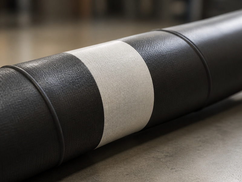
Figure 1. The marking fields a transfer hose must carry, and the two figures that must stay off the cover.
If your team reads layline markings on other hose types, the same habit of checking each field against the record applies. The layline and SAE code guide explains how a printed line is read field by field.
Table 1. The USCG 33 CFR 154.500 hose clauses with the condition each states and the facility duty it creates.
| Clause | Requirement (condition quoted) | Facility action | Record |
|---|---|---|---|
| 154.500(a) | Minimum design burst pressure at least 4 × (relief-valve setting, or maximum pump pressure where no relief valve is fitted, plus static head at the hose) | Check the assembly burst rating against the relief setting plus static head | Burst rating basis, relief-valve setting, static head |
| 154.500(b) | MAWP must be greater than the same sum | Confirm MAWP exceeds the sum, not equals it | MAWP |
| 154.500(c) | Nonmetallic hose usable for oil or hazardous material service | Confirm the tube is rated for the service class | Service class |
| 154.500(d) | Fully threaded ends, or ANSI B16.5 / B16.24 flanges, or ASTM F1122 quick-disconnect couplings | Verify the connection type fitted to the hose | Connection type and standard |
| 154.500(e) | Product name, or OIL SERVICE, or HAZMAT SERVICE—SEE LIST plus a manual-keyed symbol | Check the mark and the symbol key | Approved product list behind the symbol |
| 154.500(f) | MAWP, manufacture date and latest 156.170 test date marked, or held in records with the hose identifiable | Mark an identification code and hold dates in the record | Dates or cross-reference |
| 154.500(g) | Burst pressure and test pressure must not be marked on the hose | Remove or avoid those marks | Burst and test pressure held in the record |
| 154.500(h) | Fuel-to-vessel hose where containment cannot practically be provided at the fill pipe needs an automatic back-pressure shutoff nozzle | Confirm nozzle where that condition applies | Fill-pipe arrangement note |
3. Test and inspection duties under 33 CFR 156.170
Section 156.170 carries the recurring duties. It also requires the entire external surface of the hose to be accessible during any test or inspection. It sets the condition a nonmetallic chemical transfer hose must be in, the fluid allowed for the test, how often to test, and how accurate the gauge must be. The hose test pressure and the hose inspection interval are the two figures a facility has to schedule around. These are the duties that generate the periodic record.
156.170(c)(1): the condition test
Table 2 quotes the condition test in full. Prose adds the one point a table cannot carry: the visual and the pressure halves are a single test. A cover defect fails the hose before any pressure is applied, and a clean cover never excuses a failed proof load at 1.5 × MAWP. Both halves have to be recorded. A hose that fails the 156.170(c)(1)(i) condition can still be accepted after a static liquid pressure test passed in the presence of the Coast Guard Captain of the Port (COTP). The test medium for that test is not required to be water.
156.170(e): the test fluid
The test fluid is limited to liquids compatible with the hose tube as recommended by the hose manufacturer. Water is permitted only where the manufacturer recommends it for that tube. Check the manufacturer’s recommendation for the tube compound before you fill the hose.
156.170(f)(1): the hose inspection interval
The facility must test and inspect each hose annually, or not less than 30 days before the first transfer made more than one year after the previous tests and inspections. The annual test is the baseline.
The 30-day path is a second route that keeps a hose current when a transfer falls late in the year. Pick the route that fits the transfer schedule and show the date arithmetic in the record.
156.170(c)(3): gauge accuracy
Pressure gauges used in the test must read within 10 % of actual pressure. A gauge that drifts outside that band understates or overstates the proof load, so the hose test pressure it shows cannot be trusted. Calibrate before the test and capture the gauge reading.

Figure 2. How the three pressure figures relate: design burst, MAWP, and the 1.5 × MAWP proof test.
Table 2. The 33 CFR 156.170 test and inspection conditions a facility must meet for a nonmetallic transfer hose.
| 項目 | Condition quoted | What the facility does |
|---|---|---|
| 156.170(c)(1)(i) | No unrepaired loose covers, kinks, bulges or soft spots; no gouges or cuts penetrating the first reinforcement layer; or any other defect which would permit the discharge of oil or hazardous material through the hose material | Inspect the full hose length and record defects |
| 156.170(c)(1)(ii) | No external deterioration and, to the extent internal inspection is possible with both ends of the hose open, no internal deterioration | Inspect the outside over the full length and the inside where the ends allow |
| 156.170(c)(1)(iii) | Must not burst, bulge, leak or abnormally distort under static liquid pressure of at least 1.5 × MAWP | Run the static liquid proof test at the required pressure |
| 156.170(e) | Test fluid limited to liquids compatible with the hose tube as recommended by the hose manufacturer | Confirm the fluid against the tube recommendation |
| 156.170(f)(1) | Annually, or not less than 30 days before the first transfer made more than one year after the previous tests and inspections | Set the interval and show the date arithmetic |
| 156.170(c)(3) | Pressure gauges must read within 10 % of actual pressure | Calibrate and record the gauge reading |
4. What the facility does, clause by clause
Translate each clause into two outputs. First, an action on the hose. Second, an entry in a record. A clause with no record entry is hard to prove later, even if the work was done.
The recurring tasks a transfer facility owns for a chemical transfer hose come down to a short list:
- Keep the design check current when the relief-valve setting or the transfer layout changes.
- Verify the mark on the cover against the approved product list.
- Run the visual and pressure test on the set interval.
- Set the hose inspection interval from the actual transfer schedule.
- Record the test fluid, the gauge reading and the result.
- Pull the hose from service on a failed condition check.
The pressure duty is a design duty, not a per-transfer duty. The refusal to go beyond the marked MAWP is an operating discipline, not a clause number.
If you want the wider engineering background on why a hose test is run the way it is, the hydrostatic and impulse testing guide covers the method and the standards behind it.
5. The honest gap: a compliant record is not chemical suitability
Nothing in USCG 33 CFR 154 asks what chemical the hose tube can carry. The clause set checks pressure design, connections, marking, and a periodic proof test. A hose can pass every item and still be the wrong tube for the product.
Marking under 154.500(e) names the service, but the mark is only as good as the list behind it. If the list was written by copying a supplier page, the mark is confident and wrong.
The gap has three parts:
- Pressure compliance says nothing about chemical attack on the tube.
- A proof test uses a compatible fluid and never exposes the tube to the product.
- A resistance chart is a screening aid, not a test result.
This is the part a compliance file cannot answer. A passed annual test is evidence about pressure integrity on the test day. It is not evidence about the tube compound.
Immersion tests report volume swell, hardness change, and tensile or elongation change; a printed chart does not. Reading a chart, and choosing between charts or databases, are separate exercises with their own guides. Here the boundary is simple: a chart rating is a screening aid, never a suitability proof.
Where pressure compliance stops
A chemical transfer hose is a pressure boundary and a material choice at the same time. The pressure clauses cover the first. The chemical clauses cover the materials in contact with the product.
A hose at 1.5 × MAWP proof can pass and still lose its tube in a month. Attack is a material process, not a pressure event.
What a test result does and does not cover
A test result covers the item tested, on the day it was tested, with the fluid used. A different product, a higher temperature, or a longer exposure sits outside what that record proves.
Read a test record as a snapshot. Read a material standard as the design basis. The two do different jobs.
6. Standards that fill the gap: EN 12115 and EN 13765
Where the US rules stop, product standards start. They define the assembly, the materials and the electrical behavior that the CFR clause set leaves open.
EN 12115:2021 covers rubber and thermoplastic hose assemblies for chemicals. It defines two assembly types, Type D and Type SD, and four electrical grades. It covers chemicals in the range −20 °C to +65 °C at a working pressure of 10 bar or less.
EN 13765:2018 covers thermoplastic multi-layer, non-vulcanized composite hose for hydrocarbons, solvents and chemicals. It defines four types, Type 1 to Type 4, bores of 25 mm to 300 mm, working pressures of 4 bar to 14 bar, and working temperatures of −30 °C to +150 °C.
Electrical grade matters where static is a hazard. ISO 8330 vocabulary sets three bands. An electrically conductive or anti-static hose is below 10⁶ Ω. An electrically bonded hose is below 10² Ω. An electrically continuous hose is also below 10² Ω. Electrical testing refers to EN ISO 8031:2020.
Static guidance documents are separate from the CFR clause set. NFPA 77, API RP 2003 and IEC 60079-32-1 discuss static ignition; they are guidance, not hose clauses.
Table 3. EN 12115:2021 and EN 13765:2018 as the product standards that address what the USCG 33 CFR 154 clause set does not.
| Standard | Scope | Key figures quoted | Electrical content |
|---|---|---|---|
| EN 12115:2021 | Rubber and thermoplastic hose assemblies for chemicals, Type D and Type SD | −20 °C to +65 °C, working pressure 10 bar or less | Four grades: M, Ω, M/T, Ω/T; M/T and Ω/T through-wall resistance 10 Ω or less |
| EN 13765:2018 | Thermoplastic multi-layer composite hose, Type 1 to Type 4 | Bores 25 mm to 300 mm, working pressures 4 bar to 14 bar, −30 °C to +150 °C | Not the electrical scope of EN 12115 |
| ISO 8330 | Vocabulary for electrical terms | Conductive / anti-static below 10⁶ Ω; bonded below 10² Ω; continuous below 10² Ω | Definitions only |
| EN ISO 8031:2020 | Electrical resistance test method for hoses | Method referenced by EN 12115 | Test method only |
The way these compare to the SAE, DIN and ISO families is set out in the hose standards comparison guide. Use it when a supplier quotes a standard you do not see in the contract.
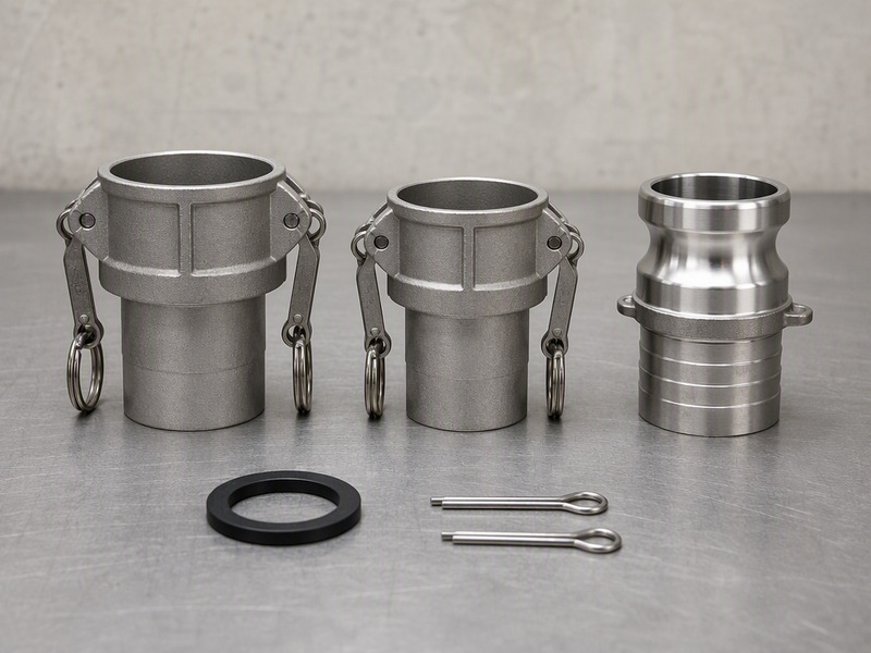
If you need a specific pressure and bore for a chemical line, the 250 psi chemical suction and discharge hose is one reference point for the range HENGHUA publishes.
7. The operations manual and the hose record
The facility operations manual is where the marking symbol from 154.500(e) resolves to a product list. It is also where the hose record lives. Section 154.740 makes that record part of the rule set, not a house convention: the facility keeps the date and result of the most recent test or examination of each item tested or examined under 156.170, and the hose information from 154.500(e) and 154.500(g) that the hose itself does not carry. Keep that record complete enough that an inspector can match a hose to its data without a phone call.
The hose record should carry, at minimum:
- Identification code as marked on the hose.
- MAWP and the basis for the design burst pressure.
- Date of manufacture and date of the latest test.
- Test fluid used and the manufacturer compatibility recommendation.
- Gauge reading and calibration state at the time of test.
- Approved product or service list the hose is cleared for.
Table 4. Fields to keep in the hose record so the facility operations manual and the hose stay linked.
| Record field | Why it exists | Clause it answers |
|---|---|---|
| Identification code | Links the hose to its dates and data | 154.500(f) |
| MAWP and burst basis | Shows the design check | 154.500(a), 154.500(b) |
| Manufacture and test dates | Shows currency of the last test | 154.500(f), 156.170(f)(1) |
| Test fluid and tube recommendation | Shows the fluid was allowed | 156.170(e) |
| Gauge reading and calibration | Shows the gauge was within 10 % | 156.170(c)(3) |
| Approved product list | Resolves the marking symbol | 154.500(e) |
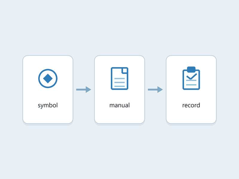
Figure 3. The record loop: a marking symbol resolves through the facility operations manual to the approved product list and the test record.
The manual is the hub
The symbol on the cover is useless without the manual. The manual is also where the approved product list is maintained and revised. Treat a product-list change as a manual change, and tell the people who load.
Keep the two lists apart
Keep the product list and a resistance chart in separate folders. The product list is what the hose is cleared for. A chart is a screening aid. Mixing them invites a chart row to be read as an approval.
The record is not the goal on its own. The goal is a hose that fits the chemical and a file that shows you checked. The chemical hose product range is the sourcing side of that check.
よくある質問
What does USCG 33 CFR 154 require for a chemical transfer hose?
It requires a compliant hose assembly, not a certificate. The assembly must meet a minimum design burst pressure of at least 4 × (relief-valve setting or maximum pump pressure plus static head) and an MAWP greater than that sum. It must use allowed connections, carry the correct marking, and pass the periodic test and inspection in 33 CFR 156.170.
What is the minimum design burst pressure for a transfer hose assembly?
The clause gives a formula, not a rating. Substitute your own relief-valve setting (or the maximum pump pressure where no relief valve is fitted) and your own static head at the hose position. As an example, a 150 psi relief setting with 25 psi of static head gives a floor of 4 × 175 = 700 psi (calculated). A data-sheet burst figure counts only once that substitution is done and both inputs sit in the record.
What is the required hose test pressure for a nonmetallic transfer hose?
The hose must not burst, bulge, leak or abnormally distort under a static liquid pressure of at least 1.5 × MAWP. The 1.5 factor applies to the MAWP, not to the design burst pressure. The same clause also requires a clean visual condition before the pressure test is run.
What is the hose inspection interval under 33 CFR 156.170?
Two dates apply and the earlier one governs. The first is the anniversary of the last test. The second sits 30 days ahead of the first transfer that comes a year or more after that test. Where a hose has a single late transfer, the second date governs. Show both dates in the record.
What must the facility operations manual contain about hoses?
The manual is where the HAZMAT SERVICE—SEE LIST marking symbol resolves to a product list. It should hold the approved product list, the identification codes, and the cross-reference to the hose record. The record carries the MAWP, the manufacture date and the latest 156.170 test date, or shows where the hose can be identified with them.
What has to be marked on a transfer hose, and what must not be?
The cover shows the service mark (product name, or OIL SERVICE, or HAZMAT SERVICE—SEE LIST plus a manual-keyed symbol), the MAWP, and an identification code. The latest test date and the manufacture date sit in the hose record, keyed to that code. Two figures stay off the cover entirely: burst pressure and test pressure.
Does the USCG issue a certificate for a compliant transfer hose?
No. There is no USCG certificate for a compliant hose. The duty sits with the facility operator, and the operator’s own record is the only proof a compliance file can show. A supplier’s test report is an input to that file, not a certificate issued by the Coast Guard.
What connections are allowed on a transfer hose assembly?
Three connection types satisfy the clause, and only three. Fully threaded ends. Flanges meeting ANSI B16.5 or B16.24. Quick-disconnect couplings meeting ASTM F1122. A coupling outside those three does not become compliant by carrying a higher pressure rating; the clause sets the connection type, and the pressure rules sit in 154.500(a) and 154.500(b).
What condition defects fail a hose inspection?
Failing conditions include unrepaired loose covers, kinks, bulges or soft spots, gouges or cuts that penetrate the first reinforcement layer, and external deterioration. A hose with any of these fails the condition test. It must also hold a static liquid pressure of at least 1.5 × MAWP without bursting, bulging, leaking or abnormally distorting.
Does CFR compliance prove a hose suits my chemical?
No. The clause set governs pressure, connections, marking and the periodic proof test. It says nothing about whether the tube compound resists the product. Use EN 12115 or EN 13765 for the assembly scope, and ASTM D471 or ASTM D543 for immersion data. Read any immersion figure with its concentration, temperature and exposure time attached.
HENGHUAについて
HENGHUA is a hose manufacturer serving distributors, chemical plant operators, EPC contractors and tank-terminal operators. The product range includes chemical discharge hose rated 150 psi, and chemical suction and discharge hose rated 150 psi and 250 psi, alongside steam, water, oil, material-handling and multipurpose lines.
The published program spans bore sizes from 3 mm to 102 mm (1/8 in to 4 in) with a 4:1 design safety factor across the site. Material call-outs used here include EPDM for dilute acids and hot water, FKM for high-temperature oils and aggressive chemicals, PTFE for nearly all chemicals, and NBR for mineral oils and hydraulic fluids.
The plant covers 35,000 m² with 95 production lines, 320+ employees, 45 QC inspectors and 25 R&D engineers holding 30+ patents. Capacity is 20 million m per year. The site is 90 km from Shanghai port and exports to 70+ countries, with a quality system under ISO 9001, IATF 16949 and ISO 14001. The in-house test lab runs burst testing to ISO 1402 and impulse testing to ISO 6803.
To discuss a transfer hose program, OEM or cut-to-length work, contact HENGHUA.
 English
  Spanish
  Portuguese
  French
  German
  Arabic
  Russian
  Indonesian
  Japanese
  Korean