
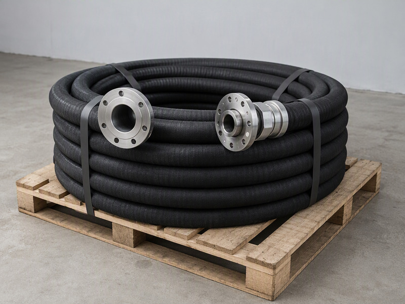
A composite hose assembly is a finished hose length that combines a multilayer thermoplastic core, a protective outer cover, and factory-fitted flange ends into one leak-tested unit.
This guide explains how such an assembly is specified and built. It covers the EN 13765 Type 1, Type 2, and Type 3 duty split, and the difference between fixed and floating flange ends. It also explains the EN 1092-1 PN and ASME B16.5 Class flange systems with their gaskets, plus the assembly, proof, and marking steps completed before shipping.
About a 15-minute read at 250 words per minute; the sections follow the order in which a composite hose assembly is specified, built, proof-tested, and released.
What Makes a Composite Hose Assembly Different
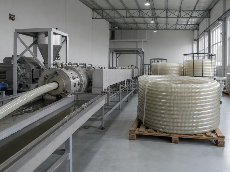
A composite hose assembly is not a rubber hose with a coupling bolted on afterward. It is a bonded, unvulcanized multilayer construction in which a thermoplastic film-and-fabric core carries the media, an outer cover protects that core, and wire or textile layers carry the mechanical load. The finished unit behaves as one engineered part rather than a set of separate components.
Because there is no cured rubber tube, the wall can be built thin and still stay flexible. Thin thermoplastic films and woven fabric are wound and bonded into a wall that bends without the stiffness of a heavy rubber build. A composite hose construction bonds those films, fabrics, and wires into one wall instead of stacking them loosely.
Electrical behavior is set layer by layer during the build. Conductive or anti-static layers can be added while the wall is built, so the unit can be ordered as a conducting, dissipative, or insulating assembly to match the site. For a wider look at how the inner materials are chosen, see the chemical hose complete guide.
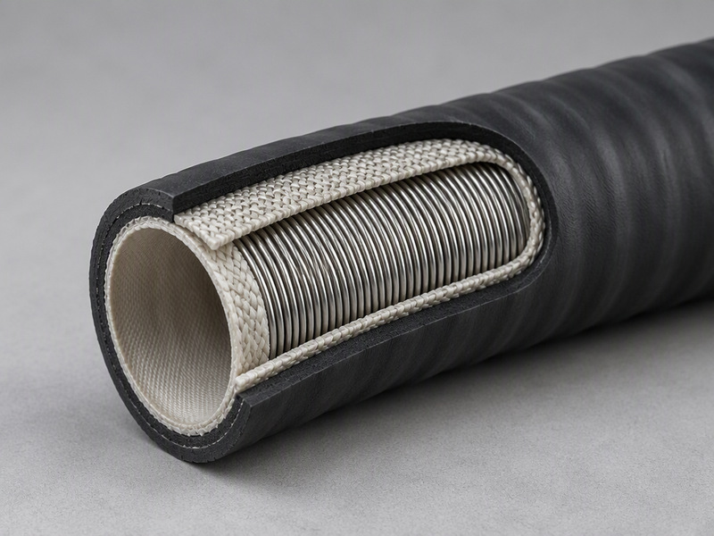
Figure 1. Inside a composite hose assembly: a thermoplastic film and fabric core, textile reinforcement, a steel helix for suction duty, and a protective outer cover.
The EN 13765 Type 1, Type 2, and Type 3 Duty Split
EN 13765 is the standard for thermoplastic multilayer composite hose and hose assemblies used with hydrocarbons, solvents, and chemicals. It sorts products by construction and duty into three types, and the type is set by the service rather than by a trade name. The three types share a composite hose construction, but they differ in the number and strength of the layers. The chemical hoses product line follows that same logic.
The three types exist because suction and discharge duties ask different things of the wall. A light transfer duty needs flexibility and chemical resistance, while a heavy dock or ship-to-shore duty needs a stronger core and a rugged cover. EN 13765 gives buyers a common way to say which band a hose belongs to before a single part is made.
Table 1. The EN 13765 composite hose types and the duties they cover.
| Type | Duty band | Anchored construction notes | Typical service |
|---|---|---|---|
| Type 1 | Lightest of the three bands | Thermoplastic multilayer build under EN 13765 | Light transfer and general chemical service where a heavy wall is not required |
| Type 2 | Intermediate band | Thermoplastic multilayer build under EN 13765 | Medium suction and discharge where more strength is justified |
| Type 3 | Heavy duty | Multilayer PP fabric and film core; PVC coated fabric cover; inner PP-coated steel wire; outer galvanized steel wire | Road and rail tankers plus dockside and ship-to-shore heavy-duty suction and discharge |
The Type 3 build is the one usually meant by heavy-duty composite hose. Its core stacks polypropylene fabric and film, its cover is a PVC coated fabric, and two wire layers run inside and outside the wall. That combination holds a large bore open against suction while surviving the abrasion of a dock or a tanker deck.
A wall that is lighter than the service calls for will not last. A wall far heavier than the duty needs adds weight and stiffness without benefit. The right type sits at the duty, with a margin the specification can justify. Where a line works in both suction and discharge, the harder of the two cases sets the type.
When a lightweight transfer hose is compared with a heavy-duty hose assembly, the difference is not only the material. It is the number and strength of the reinforcing layers, the cover thickness, and the wire support. Those choices are fixed at the factory, so the type has to be settled before the order is placed.
For a closer look at how inner liners compare across material families, see the guide to rubber, PTFE, and UHMWPE hose.
How a Composite Hose Assembly Is Built, Layer by Layer
A composite hose assembly is built from the inside out, and every layer has one job. The core carries the chemical, the reinforcement carries the load, the helix resists collapse under suction, and the cover protects everything beneath it. The order cannot be rearranged without changing the duty.
Table 2. The build sequence for a flanged chemical hose assembly and the function of each layer.
| Step | Action | Function in the wall |
|---|---|---|
| 1 | Wind the inner thermoplastic film and fabric layers | Forms the media-carrying core |
| 2 | Add the textile reinforcement | Carries the pressure and handling loads |
| 3 | Place the steel helix where suction is required | Resists collapse under negative pressure |
| 4 | Apply the outer cover | Shields the core from abrasion and weather |
| 5 | Fit the chosen flange end to each hose end | Transfers the load into the mating face |
| 6 | Proof-test, inspect, and mark | Confirms the assembly before release |
Every step in the composite hose construction adds one function to the finished wall. A suction duty shows up as a helix, a higher-pressure duty shows up as extra reinforcement, and a conductive duty shows up as added wiring. Because the wall is bonded rather than cured, the layers stay flexible together instead of splitting apart at a fold.
The end that closes the wall is as important as the wall itself. A flanged hose assembly must carry the full load of the hose into the mating face without cutting the core. That is why the flange system and the hose build are chosen together, and why the duty has to be clear from the start.
A bonded wall is a replaceable part, while field repair suits cured rubber hose. The choice between suction hose versus delivery hose turns on whether the wall has to resist collapse, and that decision is fixed at the factory rather than on site.
Fixed Flange Ends Versus Floating (Swivel) Flange Ends
A flange end ties the hose to a mating face, but it does not have to be rigid on the hose. In a fixed end the flange is locked to the hose, so the whole assembly turns when the flange is turned. In a floating, or swivel, end the flange spins on a stub while the hose stays still. That single difference decides how the joint is made up on site.
Table 3. Fixed flange ends compared with floating (swivel) flange ends.
| Point of comparison | Fixed flange end | Floating (swivel) flange end |
|---|---|---|
| How the flange sits | Locked to the hose end and unable to rotate on its own | Loose on a stub end and free to rotate |
| Bolt-hole alignment | The hose has to be turned to line the bolt holes up with the mating face | The flange spins, so the bolt holes line up without turning the hose |
| Site fit | Where the hose can be rotated during fitting and the joint is easy to reach | Where a heavy assembly must drop into a fixed bolt pattern that cannot move |
| Inspection focus | Check the flange-to-hose connection and the face alignment | Check that the swivel ring seats squarely and the stub is fully home |
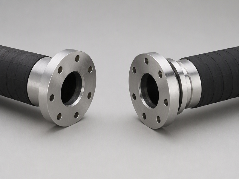
Figure 2. A fixed flange end turns with the hose, while a floating end lets the swivel flange rotate on its own.
The choice usually follows the mating face, not the hose. If the flange that is being bolted to is fixed and the hose can be moved, a fixed end is simple and easy to inspect. If the mating face cannot move and the hose is heavy or short, a floating end saves the crew from forcing the assembly into place.
A floating end takes the same load as a fixed end. The stub carries the load into the hose wall, and the swivel ring only provides the bolt pattern. A flanged hose assembly with either end form deserves the same check before it is bolted up.
Many projects use both forms on one order. It is common to fit a fixed end on one side and a floating end on the other, so a single flanged hose assembly can be lined up and then tightened from one working position. The hose couplings guide sets out how end styles compare across coupling families, and the quick-coupling hose end guide covers that coupling family (planned URL — publish before linking).
Choosing the Flange System: EN 1092-1 PN or ASME B16.5 Class
Two flange systems dominate chemical hose and piping work. EN 1092-1 uses a nominal pressure, or PN, series, and ASME B16.5 uses a pressure class, or Class, series that covers NPS 1/2 to 24. Both are widely used, and the assembly has to match whichever system the mating face uses. The same rule applies to hose end fittings and to the gaskets behind them.
Table 4. EN 1092-1 PN flanges compared with ASME B16.5 Class flanges.
| Aspect | EN 1092-1 (PN) | ASME B16.5 (Class) |
|---|---|---|
| Rating basis | Nominal pressure, PN series | Pressure class, Class series |
| Size coverage | Set by the PN series on the mating equipment | Set by the Class series, NPS 1/2 to 24 |
| Mating rule | The face and gasket come from the PN table | The face and gasket follow the Class table |
| Compatibility limit | A PN face mates with PN-drilled parts only | A Class face mates with Class-drilled parts only |
The reliable rule is to match within a single system. A PN flange and a Class flange can look similar at a glance, but their faces, bolt circles, and gaskets are built to different tables. Ordering the wrong one delays a delivery and can leave a joint that will not seal.
Bore and pressure rating both matter once the system is settled, and each one carries its own unit. Chemical hose is commonly built in bores from 3/4 in to 4 in. The hose size selection guide explains how bore is fixed by flow, while the flange rating is fixed by the system and the service. Getting both right at the quotation stage avoids rework later.

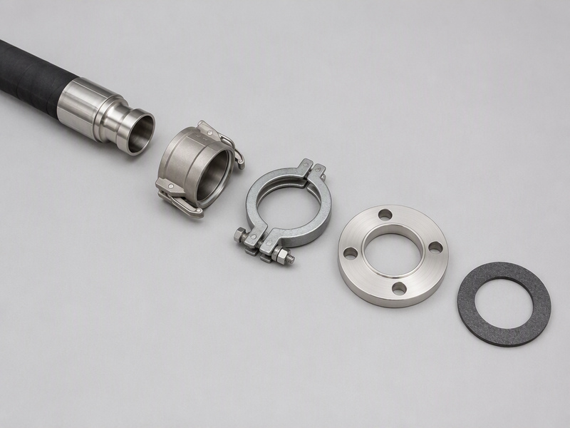
Figure 3. EN 1092-1 PN and ASME B16.5 Class flange faces are built to different tables and must be matched inside their own system.
Gasket and Sealing Selection for a Composite Hose Assembly
The gasket is the part that actually seals a flanged joint, so it has to suit the media and the temperature as well as the flange face. Common options include a PTFE envelope gasket, EPDM, and FKM. Each family covers a different band of chemicals and temperatures, and a poor choice can fail long before the hose does.
Table 5. Common gasket options for a flanged chemical hose joint and the checks that decide between them.
| Gasket option | Typical service fit | Check before release |
|---|---|---|
| PTFE envelope | Aggressive chemical duties where broad chemical resistance is needed | Confirm the envelope material suits the media and the working temperature |
| EPDM | Water and many aqueous duties | Confirm the media list before ordering, because gasket families differ in the fluids they suit |
| FKM | Oils, fuels, and many solvent duties | Confirm the working temperature sits inside the hose and gasket limits |
A gasket has to match the flange face as well as the media. A raised face and a flat face take different gaskets, so the face type has to be confirmed before the gasket is picked. If the face type is uncertain, the safe move is to photograph the mating flange and send the image with the order.
Temperature is the other half of the decision. A gasket that seals at ambient conditions can soften or harden at the top of the working range, so the whole joint should be rated as one unit. The hose, the flanged hose assembly, and the gasket should share a single working envelope, which is why hose end fittings and gaskets are usually quoted together.
Gasket handling also matters on site. A gasket should be centered on the face and used once, and a joint that has been opened should get a new gasket before it is closed again. Reusing a compressed gasket is a common cause of a slow leak that shows up only after a line is back in service.
Hydrostatic Proof, Marking, and Release Before Shipping
Every composite hose assembly should be proof-tested before it leaves the factory. ISO 1402 covers the hydrostatic test, and it confirms that the wall and the end connections hold together under pressure. Hose end fittings are part of that test, because a joint fails where the hose meets the fitting. Where an electrical class is specified, EN ISO 8031 covers the resistance test that proves the conductive or anti-static path.
Table 6. Release steps for a flanged chemical hose assembly before shipping.
| Step | What happens | Record produced |
|---|---|---|
| Cut and prepare | The hose is cut to the ordered length and the ends are prepared | Build record |
| Fit the ends | The fixed or floating flange end is fitted and secured to the wall | Build record |
| Hydrostatic proof | The assembly is proof-tested under ISO 1402 to the specified pressure | Test certificate |
| Electrical test | Resistance is checked under EN ISO 8031 when a class is specified | Test result |
| Mark and release | Marking is applied and the documents are gathered for release | Release note |
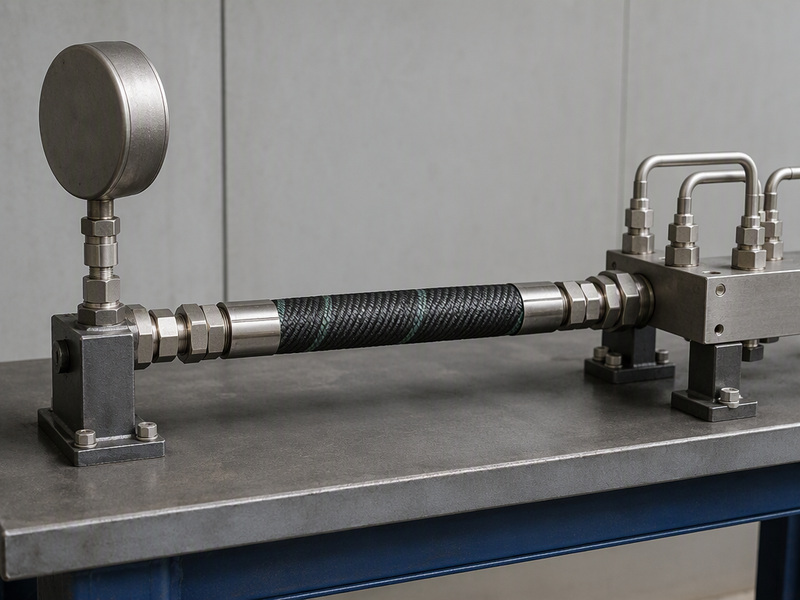
Figure 4. The assembly on the hydrostatic proof bench, with the pressure gauge and the test manifold in view.
Marking is what ties a delivered item back to its records. A marked assembly can be traced to its build sheet, its proof test, and its gasket choice, which matters when a plant has to show that a line was built to specification. An unmarked hose becomes an anonymous part the moment it is unpacked.
Specifying a Composite Hose Assembly: A Practical Checklist
Specifying the assembly is easiest when the order is written in the same order the hose is built. Start with the duty and the media, then the bore and the length, then the ends and the gaskets, and finish with the testing and the documents. Each answer narrows the build before the next question is asked.
A checklist keeps a quotation from drifting. Send the media, the concentration, and the working temperature range. Add the bore and the overall length, and state whether the duty is suction, discharge, or both.
Name the flange system, the face type, and the rating for both ends, then the gasket family and the face it will seat against. Confirm whether an electrical class is needed, and ask for the proof test certificate and the release documents with the shipment.
The answers belong together on one sheet, because the wall, the ends, and the gaskets have to match. A view of the whole connection, from the hose wall to the gasket, is the subject of how the parts match up (planned URL — publish before linking). A documented composite hose construction also makes a warranty claim easier to resolve later.
Composite Hose Assemblies FAQs
What is a composite hose assembly?
A composite hose assembly consists of a finished length of multilayer thermoplastic hose with the end connections already fitted and proof-tested at the factory. The wall is built from bonded film and fabric layers rather than a cured rubber tube, and it can include textile reinforcement, a steel helix, and conductive wiring. The finished item arrives ready to bolt up, with its flange ends matched to the mating faces and its tests recorded.
What is the difference between a fixed and a floating flange end?
A fixed flange is welded or swaged onto the hose, so the flange and the hose turn together. A swivel flange rides on a separate stub ring and spins freely, so the hose itself stays put. Both styles make the same seal against the mating face. The difference appears during assembly, when the swivel version lets a crew line the bolt pattern up without swinging a stiff, heavy hose into position.
When should a floating (swivel) flange end be specified?
Specify a swivel end when the fixed equipment gives the crew no room to work. Tanker manifolds, dock risers, and pump skids often hold a bolt pattern that cannot be adjusted, and a short or stiff hose is hard to swing into line. The swivel ring does the turning instead of the crew. If the hose can be walked around freely, a fixed end is simpler to check.
How do I choose between EN 1092-1 and ASME B16.5 flanges?
Read the nameplate on the equipment the hose will bolt to. An EN 1092-1 PN installation takes PN-drilled flanges and matching gaskets, while an ASME B16.5 Class installation takes Class-drilled parts and its own gaskets. Only parts from the same system share its bolt circle and face detail. Settle the system before the quotation is written.
What gasket should be used with a flanged chemical hose assembly?
Choose the gasket by media, temperature, and flange face at the same time. A PTFE envelope gasket suits many aggressive chemical duties, while EPDM and FKM cover other fluid families. The gasket must also match the face type on the flange, so a photo of the mating flange helps when the face is uncertain. A gasket has to come from the same system as its flange.
Which EN 13765 type is needed?
Start with the duty, not the trade name. A light transfer duty usually points to a lower EN 13765 band, while heavy dock, road tanker, and ship-to-shore work points to the Type 3 build, with its polypropylene core, PVC coated fabric cover, and two wire layers. If the duty is suction, the wall has to carry a helix so it does not collapse.
Does the finished assembly need a hydrostatic test?
Yes. A finished length is normally proof-tested under ISO 1402 before release, and that test is what shows the wall, the bonds, and the end terminations surviving as one unit. If the order calls for a conductive or anti-static grade, an EN ISO 8031 resistance check is added on top. Keep the certificate with the shipping papers; it is the link back to the batch.
Can the finished assembly handle suction service?
Yes, when it is built for it. Suction duty needs an internal helix or wire support so the wall does not collapse under vacuum, and that support is fixed at the factory. The same hose built without a helix suits discharge only. The duty has to be confirmed when ordering, because the difference is not visible once the assembly is finished.
How should the finished assembly be marked?
Marking is the thread that leads from a hose on site back to the paperwork behind it. A useful mark identifies the assembly well enough for a plant to pull up the length, the test result, and the seal that was fitted. Agree the marking content at the order stage, because the print goes on before the item is packed. Anything unmarked becomes anonymous as the wrapping comes off.
What information should be sent when requesting a quote?
Send the media and concentration, the working temperature range, the bore and length, the duty, and the flange system and face type for both ends. Add the gasket choice, any electrical class, and the documents needed with the shipment. With that list, a supplier can quote a build rather than a guess.
About HENGHUA and Next Steps
A finished assembly is only as good as the match between its wall, its ends, and the gaskets that seal it. A fixed end and a floating end both work well when they suit the mating face, and the flange system has to be confirmed before anything is built. Settling those points early turns a difficult joint into a routine one.
When the duty, the ends, and the documents are clear, the next step is a quotation. Get a quote and free samples and send the checklist above with the inquiry.
The HENGHUA engineering team prepared this guide for buyers who specify chemical hose and hose end fittings. Questions about a specific assembly can be sent through the company contact page.
HENGHUA is a professional hose and fittings manufacturer supplying global distributors, retailers, and OEM brands. The chemical hose line includes UHMWPE (UPE), XLPE, and PTFE liners plus rubber constructions such as EPDM and oil-resistant synthetic rubber, all with high-strength textile reinforcement and an optional steel helix for suction. End connections include camlock (cam and groove), flange, threaded, and clamp units. The factory offers crimped assemblies, custom lengths, jacket printing, private label, and OEM/ODM work, with factory-direct pricing, short lead times on volume, and a warranty.
 English
  Spanish
  Portuguese
  French
  German
  Arabic
  Russian
  Indonesian
  Japanese
  Korean