
A tank truck hose is specified by the loading method before anything else. Bottom loading runs product into the tank through a manifold, keeps the arm low, returns vapour through a second line and treats the hose as a short, supported pressure connection. Top loading drops product through an open hatch, which needs a longer hose, a drop pipe and a different approach to static control.
This guide compares the two arrangements on pressure, vapour handling, length, end fittings and inspection, and gives the selection table we use when a terminal is buying both.
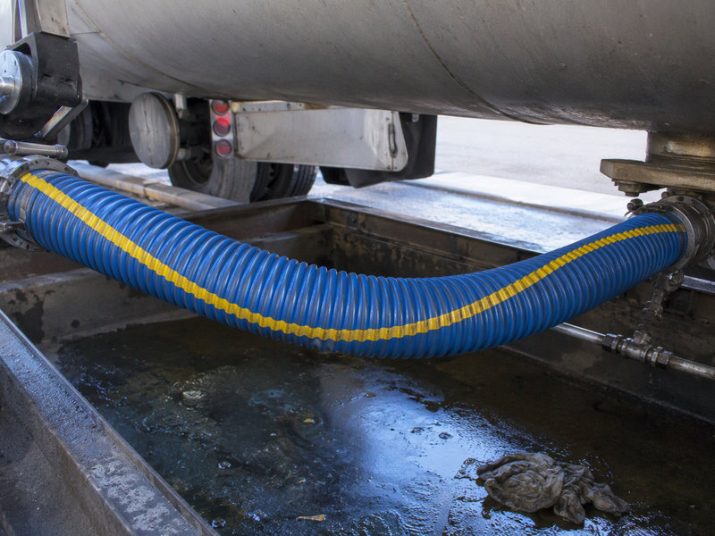
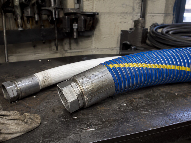
Figure 1. Bottom loading keeps the hose short and supported. The vapour line beside it is a separate assembly with its own specification.
What Changes Between Bottom and Top Loading?
The entry point into the tank changes four things: the pressure the hose sees, the amount of vapour released, the length of the run and the fittings at each end.
Bottom loading connects to a manifold near the tank sill. Product rises through the tank from below, which keeps turbulence low and reduces static generation. The hose sits between a loading arm or a pump connection and an API-style loading-arm coupler, usually supported or partly self-supporting at short length.
Top loading connects to a hatch at the top of the compartment. Product falls into the tank, so the hose has to reach higher and the operator often needs a drop pipe to avoid splash filling. The hose is longer, heavier when full, and handled more.
Both arrangements use the same family of composite hose, and the EN 13765 pressure bands set the envelope around the build. What differs is the specification around it, and that is where most purchasing mistakes happen.
Why Is Bottom Loading Gentler on the Hose?
Three reasons, and each one shows up in hose life.
Pressure at the hose is lower and steadier. A bottom loading line runs against the static head of the tank rather than a free-falling column, so pressure surges at the start and end of a load are smaller.
Vapour is contained. A closed bottom loading system returns displaced vapour through a recovery line, so the hose is not sitting in a hydrocarbon atmosphere during transfer. That matters for cover ageing and for the permeation load on the liner.
Handling is reduced. A short bottom loading assembly on a supported arm is lifted less than a top loading assembly that has to be carried up a ladder and hooked onto a hatch.
None of this makes bottom loading automatically safer. It means the hose sees a gentler duty, which is why the same build lasts longer on one arrangement than the other.
| Item | Bottom loading | Top loading |
|---|---|---|
| Typical hose length | Short, arm-mounted | Longer, handled |
| Pressure profile | Steady, low surge | Higher surge at start and stop |
| Vapour exposure | Contained in recovery line | Released at hatch unless recovered |
| Static risk | Lower, submerged fill | Higher, splash fill |
| End connection | API coupler to manifold | Flange or coupler to drop pipe |
| Handling | Arm-supported | Lifted and hooked |
| Hose wear pattern | Creasing at the arm joint | Abrasion along the length |
Table 1. How the loading method changes the duty a tank truck hose sees. Lengths and pressures are governed by the terminal design, not by the hose.
Does Vapour Recovery Change the Hose Count?
Yes. A bottom loading bay with vapour recovery needs two assemblies per arm: a liquid line and a vapour line. The vapour line is smaller in bore, runs at low pressure and carries a different concentration of hydrocarbon.
That second line is the one most often specified by copying the liquid line. It should not be. Vapour duty emphasises permeation and static conductivity rather than pressure, so the lining and the end fittings follow different logic.
On a top loading bay, recovery is usually retrofitted rather than designed in. When it is, the vapour connection frequently lands on the hatch rim, which changes the hose routing and adds a second handling step for the operator.
Either way, count the assemblies before pricing, and check the vapour line build against the duty rather than copying the liquid line. A bay that looks like four hoses is often eight.
How Long Should the Hose Be?
The hose length rule has two halves: reach the worst-case connection point, and stay off the ground. Terminals usually get the second one wrong.
A tanker unloading hose faces the same rule in reverse. A hose that touches the ground picks up grit that works into the cover. A hose coiled to take up slack creases at the same point on every load. Both shorten life more than the product does.
For a bottom loading arm, the hose length is set by the arm geometry and the range of tank positions. Measure the furthest coupler position and add the bend allowance at each end. Do not add a metre for comfort.
For top loading, the run is fixed by the hatch height plus the drop pipe. Where the drop pipe is part of the assembly, the hose only carries product to the top of the pipe, and the pipe carries it into the tank.

Figure 2. A bottom loading arm at the manifold. The hose runs short and horizontal from the arm to the tanker.
Which End Fittings Suit Each Arrangement?
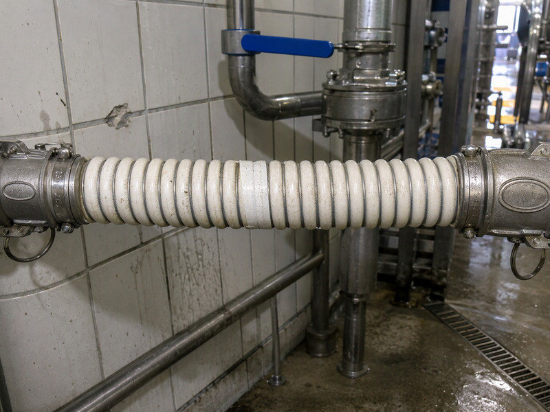
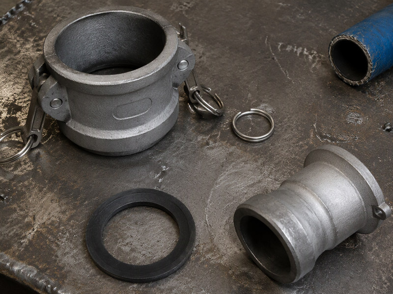
Bottom loading is dominated by the API coupler on the tank side and a flanged or camlock connection on the arm side. The coupler is a standardised interface, so the hose build follows it rather than the other way round.
A top loading assembly is more varied at the hatch. Connections use flanges, camlocks or a threaded drop pipe adapter depending on the fleet and the decade the terminal was built. That variety is why top loading assembly orders need a photo of the connection, not just a size.
Two fitting choices repay attention on both arrangements. A swivel or floating flange on the arm side takes the twist out of the hose as the arm moves, and a properly sized gasket prevents the leak that operators try to fix by over-tightening.
Material follows the product, not the arrangement. Stainless is the default for aggressive streams and aluminium keeps weight down on a long top loading run, at the cost of wear at the coupling.
What About Drop Hose on Top Loading?
A drop hose, or drop pipe, is the section that carries product from the hatch to near the tank bottom, and it is the part of a tanker composite hose order most often left out. It exists to prevent splash filling, which generates static and vapour.
Some terminals use a rigid drop pipe and a short flexible connection at the hatch. Others use a length of composite hose as the drop, weighted at the end. The second approach is simpler and puts more demand on the hose.
If the hose is the drop, three properties matter: weight, resistance to kinking when empty and the ability to drain. A heavy hose hanging in a tank is hard to retrieve, and an empty hose that kinks on the way down traps product.
Where a terminal runs both arrangements, the drop hose specification should be written separately from the arm hose. Mixing them produces an assembly that is over-specified for one job and marginal for the other.
How Do the Inspection Routines Differ?
The hose itself is inspected the same way in both cases, and the inspection programme is the right starting point. The differences sit in what surrounds it.
Bottom loading inspection includes the coupler, the vapour line and the arm joints, because a failure in any of them looks like a hose failure from the operator’s position. Top loading inspection includes the hatch, the drop pipe and the handling route, since a hose damaged in transit to the hatch will fail before its pressure rating is reached.
Two checks are worth adding to both routines, and they apply to a tanker unloading hose as much as to a loading one. Look at the cover where the hose rests on a support or a hatch rim, because abrasion starts there. And check the end fittings after every shift on top loading, because a hose that is lifted by its coupling eventually loosens the ferrule.
Retirement criteria should be written down and identical for both, because a tank truck hose judged against two different standards will always pass one of them. Swelling, a soft band behind the fitting, cover damage that exposes reinforcement, or a failed pressure test.
Which Tank Truck Hose Build Should You Specify?
Start from the product and the pressure, then adjust for the arrangement. A tank truck hose chosen on product alone will be right about chemistry and wrong about reach.
| Requirement | Specification |
|---|---|
| Bottom loading, gasoline, 10 bar | PP or UHMWPE liner, conductive build, API coupler |
| Bottom loading, multi-product, 15 bar | PTFE liner, floating flange one end |
| Vapour recovery line | Small bore, low permeability liner, conductive |
| Top loading, diesel, 10 bar | PP liner, drop hose length, abrasion-resistant cover |
| Top loading, aggressive solvent | PTFE liner, stainless fittings, sleeved cover |
| Both arrangements, one fleet | Standardise the coupler, vary the liner |
Table 2. Specification starting points for tank truck hose by arrangement. Confirm pressure and derating against the terminal design.
The last row is the one that saves money at fleet level. Standardising the tank-side connection while allowing the liner to vary keeps the operator routine simple and lets purchasing buy the right hose for each product.
What Does the Terminal Design Change?
Two terminals with the same loading method can still need different hoses, because the design around the bay sets the pressure and the reach.
A gravity-fed bay loads slowly at low pressure, and the hose sees little more than the static head. A pumped bay with a positive displacement pump and a fast shut-off valve produces a pressure spike at the end of every load, and that spike is what fatigues the reinforcement.
Recovery design matters too. A bay with a dedicated vapour return runs cooler and drier than one without. The hose on the dry bay ages differently, and the cover cracking that appears after two summers is usually a vapour exposure effect rather than a product effect.
Where a terminal also unloads, the same hose is often used in reverse. A tanker unloading hose sees the product from the other side of the pump and may run at a different pressure, so the rating has to cover both directions.
How Do I Train Operators So They Stop Swapping the Bottom and Top Loading Hoses?
Training is where the specification earns or loses its money. An operator who understands why the two hoses differ will stop swapping them.
Start with identification. If the bottom loading assembly and the top loading hose are marked only by length, they will be confused during a busy shift. Colour, a tag or a fitted end that only matches one connection removes the choice.
Then the drain routine. A top loading hose that is lowered without draining carries product into the hatch area, and a bottom loading assembly left full puts product in the arm when it is disconnected.
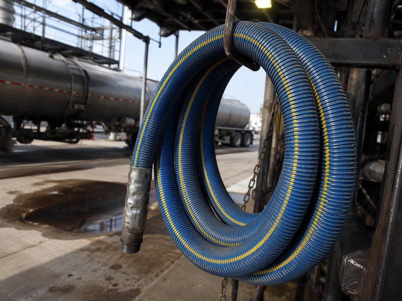
Then the handling rule. Lifting by the coupling, dragging over a kerb and coiling on a hook are the three habits that cost the most hose life in a truck bay, and all three are trainable.
What Does a Truck Bay Inventory Look Like?
A bay running both methods usually holds more assemblies than the drawing suggests, and the tanker unloading hose on the return leg is the one most often left out of the count. Counting them properly is the first step to controlling cost.
- Liquid line per arm, one per product group
- Vapour recovery line per arm
- Drop hose or drop pipe for each top loading position
- Spare assembly per critical product
- Test spool for pressure testing
That list is five categories before any spare philosophy is applied. Terminals that budget from the P&ID alone usually under-count by the vapour line and the drop hose.
Writing the list down also exposes duplication. Two product groups that never load at the same time can share one bottom loading hose, and that saving is usually worth more than a discount negotiation.
Three site states change the answer. A single-product depot needs one liquid line per arm and one spare. A multi-product terminal needs the liner to vary while the coupler stays the same. A third-party loading rack needs a hose that any carrier can connect, so the coupler standard matters more than the liner.
Häufig gestellte Fragen
Is a bottom loading hose interchangeable with a top loading hose?
Not in practice. A bottom loading hose is short and arm-mounted, while a top loading hose has to reach a hatch and be handled. A compromise assembly is too long for one job and too short for the other.
What pressure should a tank truck hose be rated for?
Above the maximum pump pressure plus static head, with margin. Terminal design sets the number, and typical loading duty sits inside EN 13765 Type 2, which gives 10 bar working, 15 bar proof and 40 bar burst at −30 to +80 °C.
Does a bottom loading hose need to be conductive?
Where the product is flammable, the assembly should be part of a bonded system. Conductivity is a hose property, and the connection to earth is a terminal property; both are needed.
Why does the vapour line need a different hose?
It carries a different medium at low pressure, and permeation matters more than strength. Copying the liquid line is a common and costly shortcut.
How often should the hose be pressure tested?
Follow the terminal’s inspection programme and local rules. The test interval matters less than the record, because an untested hose with a certificate is still an untested hose.
Is a longer hose safer on top loading?
No. Extra length adds weight, creates a coil that traps product and puts the hose on the ground. Length should match the reach, no more.
Can a composite hose be used as a drop hose?
Yes, where it is rated for the duty and can be drained. Confirm the weight and the kink behaviour when empty, which is where drop hoses fail.
Über HENGHUA
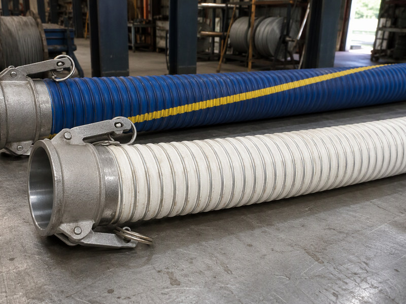
HENGHUA supplies composite hose for tank truck loading with PP, XLPE, UHMWPE and PTFE liners, in the 10 bar, 15 bar and heavy-duty builds, with API couplers, flanges or camlocks on the ends. Vapour recovery lines are built to their own specification rather than copied from the liquid line.
Send the loading arrangement, product slate and terminal pressure, and we will set out the hose and vapour line specification together, including the fittings at each end.

 English
 Spanish
 Portuguese
 French
 German
 Arabic
 Russian
 Indonesian
 Japanese
 Korean