
Identifying a hydraulic hose fitting comes down to three measurements and one visual check: thread outside diameter, threads per inch (or metric pitch), whether the thread is straight or tapered, and the shape of the sealing face.
Take those four readings and almost all hydraulic hose fittings resolve into one of eight end-connection families — JIC 37° flare, ORFS, ORB, NPT, BSPP, BSPT, metric 24° cone, or SAE flange. Selection is the second half of the job and follows a fixed sequence: hose bore, working pressure, fluid and temperature, the port on the machine, routing, and fitting material. This guide covers both halves — the identification method you can run at a bench or in a muddy field, comparison and size charts for every common family, seal-material and torque data, the failure modes that actually cause leaks, realistic cost bands, and a supplier checklist you can copy straight into a quote request.
1. The Short Answer: How Do You Identify a Hydraulic Hose Fitting?
A hydraulic hose fitting is identified by measurement, not by appearance. Thread outside diameter and threads per inch identify the *thread standard*; the sealing face identifies the *family*. A 7/16-20 straight thread ending in a 37° cone is a JIC fitting. The same 7/16-20 straight thread with an O-ring sitting in a groove at the base is an ORB fitting. Both share a thread; only the seal tells them apart.
That distinction matters because thread-compatible fittings are frequently not seal-compatible. A JIC male body will screw into an ORB boss port of the same thread size, and it will leak — the JIC cone has nothing to seal against in a port designed for an O-ring. Cross-family assembly of thread-matched parts is one of the most common causes of a leak that “should not be leaking.”
Start Here: What to Read First, Depending on What You Are Doing
Table 1a. Where to start in this guide, by reader
| If you are… | Read first | Have ready |
|---|---|---|
| Fitting in hand, machine down | Section 4 (five-step identification), then Table 10 for torque | A caliper, a pitch gauge and a photograph of the fitting beside a steel rule |
| Specifying a new assembly | Section 7 (six-step selection), then the checklist at the end of Section 7 | Bore, working pressure, fluid, temperature, port type and routing |
| Buying or quoting | Section 10 (cost bands), then the checklist at the end of Section 7 | Family, dash size, material, quantity, annual volume and documentation needs |
| Investigating a repeat failure | Section 9 (failure modes) and Section 11 (assembly rules) | The failed part, the fluid temperature and the age of the assembly |
Table 1. The four readings that identify a hydraulic hose fitting, and what each one tells you
| Reading | How to take it | What it tells you |
|---|---|---|
| Thread outside diameter | Digital caliper across the thread crests | The nominal size — sixteenths of an inch for UNF threads, millimetres for metric |
| Threads per inch or pitch | Thread pitch gauge, or a steel rule across one inch of thread | The thread series: UNF at 20, 18, 16, 14 or 12 TPI; pipe at 27, 18, 14 or 11.5 TPI; Whitworth at 28, 19, 14 or 11 TPI; metric at 1.5 or 2.0 mm |
| Straight or tapered | Sight along the thread, or caliper the thread at both ends and compare | Pipe threads (NPT, NPTF, BSPT) taper; UNF, ORFS, ORB, BSPP and metric threads run straight |
| Sealing face | Clean the fitting and look at the end under good light | 37° flare, 45° flare, flat face with O-ring, O-ring boss, 60° cone, bonded washer, or a four-bolt flange head |
Clean the fitting before you measure it. Paint, cured oil and thread sealant all add thickness, and a reading error of only 0.3 mm is enough to put you on the wrong row of a cross-family chart. Adjacent thread sizes of the same family are safely far apart — a 9/16-18 measures 14.29 mm across the crests and an 11/16-16 measures 17.46 mm, a difference of 3.18 mm — but families at the same nominal size are not: a 1/2-inch NPT thread measures about 21.3 mm while a 1/2-inch BSPP measures about 21.0 mm, so paint, cured oil or sealant can move the reading across that boundary. On assemblies we have measured, a dirty JIC -6 fitting commonly reads 0.2 to 0.4 mm oversize across the crests.
Two habits make hydraulic hose fitting identification faster in practice. Measure twice — thread outside diameter first, then pitch — because a single reading is frequently ambiguous, and 1/4 BSPP at 19 TPI against 1/4 NPT at 18 TPI is exactly where people guess wrong. Then photograph the fitting beside a steel rule before you send the enquiry, because knowing how to identify hydraulic fittings from a scaled photograph is routine work for a hose manufacturer and resolves more order queries than a paragraph of description.
2. What Are Hydraulic Hose Fittings? The Five Parts of Every Connection
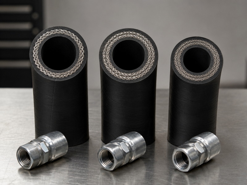
A hydraulic hose fitting is the metal end connection that grips the hose at one end and adapts to a port, tube or second hose at the other. It is the part that turns a length of hose into a pressure-tight, machine-mountable line. Every fitting is specified twice — once for how it attaches to the hose, once for how it attaches to the machine — and those two specifications are independent.
Inside a crimped hose end, five components do the work.
Table 2. The five functional parts of a crimped hydraulic hose end fitting
| Part | Function | What fails if it is wrong |
|---|---|---|
| Insert (nipple) | Pushes into the hose bore and carries the fluid path | Undersized insert restricts flow and overheats the fluid |
| Ferrule (socket, shell) | Compresses the hose cover and reinforcement onto the insert | Wrong ferrule for the hose construction = fitting pull-off under pressure |
| Nut (coupling nut) | Threads onto the mating port and applies the sealing load | Wrong thread form cross-threads and destroys both threads |
| Sealing face | Creates the actual seal: flare cone, O-ring face, boss O-ring, cone seat or flange face | Any mismatch here leaks regardless of how tight the nut is |
| Seal element | Elastomeric O-ring, bonded washer or copper washer, where the family requires one | Wrong compound swells, hardens or dissolves in the system fluid |
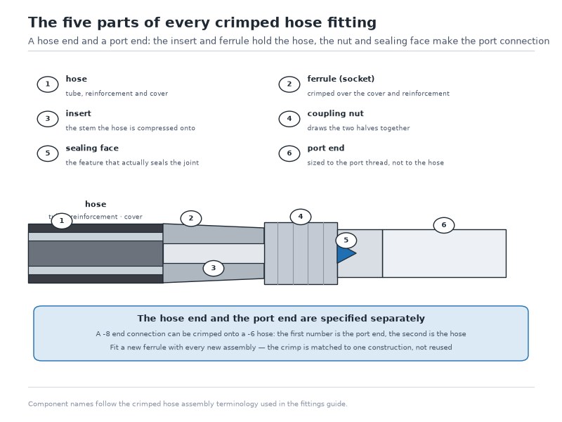
Figure 1. A crimped hydraulic hose fitting is a hose end plus a port end. The insert and ferrule hold the hose; the nut and sealing face make the port connection. The two halves are specified separately.
The Hose End and the Port End Are Two Different Decisions
The hose end answers “how does this grip the hose?” — a crimped ferrule, a reusable threaded socket, or an interlocking skive system. The port end answers “what is on the machine?” — a JIC male, an ORFS male, a flange, a banjo bolt, or a stud end that takes a nut.
Because the two are independent, one hose end can carry any port end. A -8 double-wire-braid hose can be supplied with a -8 JIC male at one end and a -8 ORFS female swivel at the other, and that is a normal, off-the-shelf assembly rather than a special. When you request a quote, always give both ends separately, plus the angle.
A detail that trips people up constantly: the dash size of the hose is not the dash size of the thread. A -8 hose (1/2 inch bore) does not have a 1/2-inch thread. Its JIC end is 3/4-16, and its ORFS end is 13/16-16. Dash sizes describe the *hose*, and separately the *thread*; they only coincide by convention within a family, not across families.
Crimped and Reusable Fittings: Permanent vs Field-Serviceable
Hydraulic hose ends fall into two families. Crimped ends are swaged onto the hose with a press and the correct die for that exact hose-and-fitting combination. Reusable ends thread onto the hose: the socket screws over the cover, the insert threads into the bore. The choice between them is a logistical decision as much as a technical one.
Table 3. Crimped versus reusable hydraulic hose ends
| Factor | Crimped (permanent) | Reusable (field-attachable) |
|---|---|---|
| Tooling needed | Crimper plus the correct die and crimp specification | Two wrenches and a vise |
| Pressure capability | Full rating of the hose and fitting family | Not recommended above about 1,500 PSI working pressure (HENGHUA supply limit); lower than the equivalent crimped end |
| Hose compatibility | Any construction with a validated crimp spec | Limited to specific hose constructions, usually textile or light wire braid |
| Repeatability | High — every assembly comes off the same die | Depends on the operator |
| Best use | OEM production, high pressure, impulse service | Emergency repair in the field, temporary lines, low-volume jobs |
| Reuse | Not reusable; the fitting is cut off | Reusable if the threads and seat are undamaged |
We do not recommend reusable fittings above roughly 1,500 PSI working pressure, and we do not supply them for four- and six-spiral hose. The socket cannot develop the same grip on a multi-spiral reinforcement that a crimped ferrule does, and a fitting that pulls off a 4,000 PSI line is a serious safety event rather than an inconvenience.
3. Types of Hydraulic Hose Fittings: The Eight End Connections You Will Meet
Eight families cover the overwhelming majority of hydraulic equipment in service worldwide. They are JIC 37° flare, ORFS, ORB, NPT/NPTF, BSPP, BSPT, metric 24° cone and SAE flange; each one is defined by a thread and a seal, and each has a pressure band where it is the sensible choice. Any survey of the types of hydraulic hose fittings therefore reduces to two questions per family: what thread does it use, and what does it seal on?
This section answers those two questions in buying terms — what each family is used for, how it is identified at the bench and what it costs. The published thread sizes, thread angles and seal geometry behind them are set out standard by standard in our hydraulic fitting types guide.
JIC 37° Flare (SAE J514, ISO 8434-2)
JIC uses a straight UNF thread with a 37° cone on the male and a matching 37° seat on the female. The seal is metal-to-metal at the cone, so no elastomer is involved — which is why JIC survives heat that destroys an O-ring, and also why a scratched cone leaks.
The thread moves in a predictable pattern: -4 is 7/16-20, -6 is 9/16-18, -8 is 3/4-16, -10 is 7/8-14, -12 is 1 1/16-12, -16 is 1 5/16-12. Published ratings for carbon steel JIC fittings start at about 6,000 PSI in the smallest sizes and fall to roughly 3,000 PSI at -16 and above, which is why JIC is normally paired with single- and double-wire-braid hose rather than spiral. Better routing flexibility than ORFS, with a lower ceiling in the larger sizes.
ORFS: O-Ring Face Seal (SAE J1453, ISO 8434-3)
ORFS puts an O-ring in a groove on a flat face. The male flat face presses the O-ring against the female flat face, so the threads carry load and the O-ring does the sealing. Straight UNF thread: -4 is 9/16-18, -6 is 11/16-16, -8 is 13/16-16, -10 is 1-14, -12 is 1 3/16-12, -16 is 1 7/16-12.
Two practical consequences follow. First, ORFS holds higher pressure than JIC in the same size, and published carbon steel ratings commonly reach 6,000 PSI in the smaller sizes — so it is the natural partner for four- and six-spiral hose. Second, the O-ring is a wear item. When a field engineer reports an ORFS joint weeping after a thousand hours, the first thing to check is a hardened or nicked O-ring, not the torque.
ORB: O-Ring Boss (SAE J1926, ISO 11926)
ORB is a straight-thread *port* connection: the O-ring sits at the base of the male thread and seals against the flat face of a boss, usually with a locknut and washer arrangement. Thread sizes are identical to JIC for the same dash — -4 is 7/16-20, -6 is 9/16-18, -8 is 3/4-16, -12 is 1 1/16-12.
That identical thread is the trap described earlier. An ORB male will start into a JIC female without protest and will leak, because the O-ring has no flat face to seal against. If a joint leaks only after you change a hose, check whether someone installed a JIC end into an ORB port.
NPT and NPTF Pipe Thread (ASME B1.20.1, SAE J476)
NPT is a tapered 60° pipe thread that seals by deforming the threads together, usually with sealant. NPTF (dryseal) is a controlled version that seals without sealant. Common sizes: 1/4-18, 3/8-18, 1/2-14, 3/4-14, 1-11.5, 1-1/4-11.5, 2-11.5.
NPT has two limitations worth stating plainly. It is a low-to-medium pressure connection — the thread itself is the seal, so it cannot resist high impulse the way a face seal does. And it is not reliably reusable: the threads deform each time they are made up, so a joint that has been apart three times may simply weep. On return lines and low-pressure circuits that is acceptable; on a 4,000 PSI pressure line, NPT is the wrong answer.
BSPP and BSPT (ISO 228-1, ISO 7-1)
British Standard Pipe comes in two forms that share a 55° Whitworth thread profile. BSPP (also written G) is parallel and seals on a bonded washer against a flat face, or on a 60° internal cone in the ISO 1179-2 port style — ISO 1179 is the international standard for those stud ends and their 60° cone seats. BSPT (also written R) is tapered and seals like NPT, by thread interference. Sizes: 1/8-28, 1/4-19, 3/8-19, 1/2-14, 3/4-14, 1-11.
The 55° thread angle is the single most reliable way to separate BSP from NPT on a bench. An NPT 1/2-14 and a BSPP 1/2-14 share a name and a thread count but not an angle, not a major diameter, and not a seal. Threading one into the other damages both.
Metric 24° Cone and Metric Parallel (ISO 8434-1, DIN 2353, DIN 3865)
Metric fittings come in two competing sealing conventions. The 24° cone design (DIN 2353 / ISO 8434-1) uses a 24° cone on the male nipple with a matching seat in the female, in light and heavy series, and the same tube outside diameter carries a different thread in each series — for example L 10 mm is M16×1.5 while S 10 mm is M18×1.5, and L 12 mm is M18×1.5 while S 12 mm is M20×1.5. The full DIN 2353 light and heavy series table lists every size in both series. The metric parallel design (DIN 3865) uses a straight metric thread with a 60° internal cone or an O-ring face, and is often the metric equivalent of a BSPP port; the two are distinguished by thread form, not by the cone angle.
Metric is identified by pitch in millimetres, not threads per inch, which is the cleanest way to tell it apart from everything else. A pitch gauge that reads 1.5 mm is metric; nothing inch-based comes close.
SAE Flange: Code 61 and Code 62 (ISO 6162-1 and 6162-2)
Four-bolt split flanges handle the large-bore, high-flow end of the hydraulic range where a threaded connection becomes impractical. Code 61 is the standard-pressure version, commonly published to about 3,000 PSI, and Code 62 is the high-pressure version, commonly published to about 6,000 PSI. The two are not interchangeable: Code 62 uses a larger flange head and a wider bolt circle, so the bolt pattern itself identifies which one you have.
Flanges appear on suction and return lines, on large cylinders, and on ports above roughly 1-1/4 inch where threading the port would be impractical. They are also the family where bolt torque sequence matters most — uneven bolt load is the standard cause of a weeping flange.
Banjo and Specialty Ends
A banjo end uses a hollow bolt through an eye, sealed by copper or bonded washers on both faces. It exists to solve a plumbing problem rather than a pressure problem: it lets a line exit perpendicular to a port in a space where an elbow will not fit. Banjo ends appear on pilot lines, brake circuits, transmissions and tight machine geometry. They are not a high-pressure solution — the hollow bolt is the weak link.
Other ends worth recognising by name include sae 45° flare (SAE J512), which uses a 45° cone rather than 37° and is common on older and automotive equipment; swivel nuts, which allow the fitting to be oriented after tightening; and stud ends, which take a separate nut and are used where the port itself is a stud rather than a female thread.
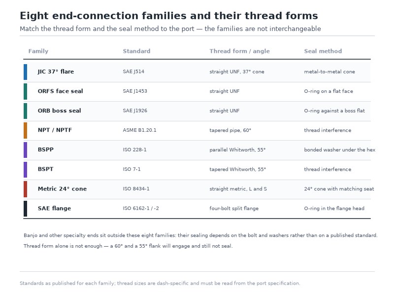
Figure 2. The eight families compared by thread form and seal type. Thread form decides what will screw together; seal type decides what will hold pressure.
Table 4. Hydraulic hose fitting types compared by thread, seal, typical pressure band and where each is used — the first eight rows are the eight end-connection families; the Banjo row is a specialty end outside that count
| Family | Standard | Thread form | Seal method | Typical working pressure | Where you find it |
|---|---|---|---|---|---|
| JIC 37° flare | SAE J514, ISO 8434-2 | Straight UNF | Metal-to-metal 37° cone | Up to about 6,000 PSI in the smallest sizes, down to about 3,000 PSI at -16 and above | Mobile equipment, pilot and medium-pressure lines |
| ORFS face seal | SAE J1453, ISO 8434-3 | Straight UNF | O-ring compressed on a flat face | Up to about 6,000 PSI | High-pressure and high-impulse circuits, spiral hose |
| ORB boss seal | SAE J1926, ISO 11926 | Straight UNF | O-ring against a boss flat | Up to about 6,000 PSI | Port connections on pumps, valves, cylinders |
| NPT / NPTF | ASME B1.20.1, SAE J476 | Tapered 60° pipe | Thread interference, with or without sealant | Up to about 3,000 PSI, often de-rated in impulse service | Return lines, air and water, older equipment |
| BSPP | ISO 228-1, ISO 1179 | Straight 55° Whitworth | Bonded washer on a flat face, or 60° cone | Commonly to about 5,000 PSI in the common sizes, depending on port design | European and imported machinery |
| BSPT | ISO 7-1 | Tapered 55° Whitworth | Thread interference with sealant | Comparable to NPT, lower in impulse duty | European machinery, older ports |
| Metric 24° cone | ISO 8434-1, DIN 2353 | Straight metric, light and heavy series | 24° cone with matching seat | Medium to high, light and heavy series differ | European and Asian equipment, DIN-standard machines |
| SAE flange | ISO 6162-1 (Code 61), ISO 6162-2 (Code 62) | Four-bolt split flange | O-ring in the flange head, retained by bolts | About 3,000 PSI (Code 61), about 6,000 PSI (Code 62) | Large bore, high flow, suction and return lines |
| Banjo | Manufacturer-specific | Straight metric or UNF bolt | Copper or bonded washers on both faces | Low to medium; set by the bolt and washer rather than by a published band | Pilot lines, brakes, tight routing |
The pressure figures in this table are typical published industry values for steel fittings; the manufacturer’s data for the exact size and material governs, and the rating always falls as the thread size grows.
4. Hydraulic Hose Fitting Identification: A Five-Step Method
This sequence works on a clean bench with a caliper and a pitch gauge, and it narrows an unknown fitting to a single family in under three minutes. Run the steps in order; skipping to the seal face before you have the thread reading produces confident wrong answers. It is also the method we teach new technicians, because knowing how to identify hydraulic fittings by measurement rather than by recall takes the guesswork out of a parts counter.
Step 1: Measure the Thread Outside Diameter
Take the caliper reading across the thread crests, not the flanks. For UNF threads, the reading maps almost directly onto the dash size, because the dash number is the thread outside diameter expressed in sixteenths of an inch. A reading near 14.3 mm (0.5625 in) is a 9/16 thread, which is a -6. A reading near 19.1 mm (0.75 in) is a 3/4 thread, which is a -8.
For pipe and metric threads the OD is not a clean sixteenth, which is itself a useful signal. A 1/2-inch pipe thread measures roughly 21.3 mm across the crests — noticeably larger than the 12.7 mm its name suggests, because pipe sizes refer to the bore, not the thread. This is also where hydraulic hose fitting sizes stop lining up across families: a -6 JIC, a -6 ORFS and a -6 ORB are three different threads at three different diameters, and only the dash number is shared.
Step 2: Count the Threads Per Inch, or Read the Pitch
Lay a steel rule along one inch of thread and count the peaks, or use a thread pitch gauge and find the leaf that seats perfectly with no rock. TPI is the fastest discriminator between families that share a size name:
- 20, 18, 16, 14 and 12 TPI on a straight thread points to UNF — JIC, ORFS or ORB
- 27, 18, 14 and 11.5 TPI points to pipe threads — NPT or NPSM
- 28, 19, 14 and 11 TPI points to Whitworth — BSPP or BSPT
- A metric pitch gauge reading 1.5 mm or 2.0 mm points to metric
Step 3: Decide Whether the Thread Is Straight or Tapered
Sight along the fitting from the side with a light behind it. A tapered thread visibly narrows toward the end, and the first two or three threads will usually look flattened or incomplete because a tapered thread is cut from a smaller start diameter. Caliper the thread OD near the nose and again near the shoulder: a difference of roughly 1 mm or more across a 1/2-inch fitting means tapered, which means NPT, NPTF or BSPT rather than a straight-thread family.
Step 4: Identify the Sealing Face
The sealing face is the reading that names the family, and it needs only a clean fitting and good light.
- A smooth cone inside the end, roughly 37°, is JIC
- A wider, shallower cone at about 45° is SAE 45° flare
- A flat face with a machined groove holding a black O-ring is ORFS (male) or a flat-face swivel
- A short straight thread with an O-ring seated at the base, and usually a locknut, is ORB
- A wider cone seat at about 60° inside a straight thread is the metric parallel or BSPP cone style
- A flat machined face with no cone and no groove usually seals on a bonded washer — BSPP or metric parallel with a washer
- A rectangular head with four bolt holes is an SAE flange
Step 5: Read the Markings and Confirm Against the Hose
Most fitting bodies carry a manufacturer mark, a material code and sometimes the dash size. Markings are a confirmation, never the opening move. Treat the stamping as the last step of hydraulic hose fitting identification rather than the first — aftermarket and unbranded fittings may carry nothing at all, and worn stampings mislead. Once you have a candidate family, confirm it against the hose: an ORFS end on four-spiral hose is a coherent assembly, while the same end on 100R3 textile hose suggests the assembly was built from whatever was on the shelf.
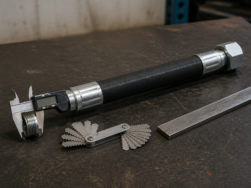
Figure 3. Steps 1 and 2 on the bench: thread outside diameter from the caliper, threads per inch from the pitch gauge. Together they identify the thread standard before the seal face names the family.
Table 5. Identification data for the common fitting families — thread size by dash, JIC / ORB male thread outside diameter, and seat geometry; the ORFS thread is one size larger than the JIC and ORB threads at the same dash size
| Dash | JIC 37° flare thread | ORFS thread | ORB thread | JIC / ORB male thread OD (in / mm) | Seat geometry |
|---|---|---|---|---|---|
| -4 | 7/16-20 | 9/16-18 | 7/16-20 | 0.44 / 11.1 | JIC 37° cone vs ORB boss O-ring share this thread |
| -6 | 9/16-18 | 11/16-16 | 9/16-18 | 0.56 / 14.2 | ORFS is one thread size larger than JIC and ORB here |
| -8 | 3/4-16 | 13/16-16 | 3/4-16 | 0.75 / 19.1 | A captive O-ring on a flat face marks the ORFS end |
| -10 | 7/8-14 | 1-14 | 7/8-14 | 0.88 / 22.2 | 14 TPI on all three; the seat decides |
| -12 | 1 1/16-12 | 1 3/16-12 | 1 1/16-12 | 1.06 / 26.9 | JIC and ORB match at 1 1/16-12; ORFS does not |
| -16 | 1 5/16-12 | 1 7/16-12 | 1 5/16-12 | 1.31 / 33.3 | The threads no longer separate the three; check the seat |
| -20 | 1 5/8-12 | 1 11/16-12 | 1 5/8-12 | 1.63 / 41.3 | Seat condition, not thread wear, is the usual failure here |
| -24 | 1 7/8-12 | 2-12 | 1 7/8-12 | 1.88 / 47.6 | At this size flange ends take over from threads |
How to Identify a Fitting You Cannot Remove From the Machine
When a fitting is buried behind a hose guard on an excavator, full measurement is impossible. Three shortcuts work in that situation.
- Read the mating part, not the fitting. The port or tube nut on the machine carries the same thread, and it is usually more accessible.
- Use the thread pitch gauge only. Pitch alone separates NPT at 14 TPI from BSPP at 14 TPI, because the gauge leaf angle does not lie — but you must still confirm 55° versus 60° by eye against a known sample.
- Compare against a known fitting. Carry a set of tagged reference fittings in the service truck: one JIC -6, one ORFS -6, one ORB -6, one BSPP 3/8, one metric M16×1.5. Offering each up to the unknown port identifies the family in seconds by which one sits flush.
The Four Look-Alike Traps That Cause Most Wrong Orders
Each of these traps produces the same field symptom: a joint that tightens, holds at low pressure, and then weeps once the oil is warm. Knowing how to identify hydraulic fittings by gauge rather than by eye is what prevents all four.
- NPT versus BSPP at 1/2-14. Same size name, same thread count, different thread angle and different major diameter. They will usually start to engage and then bind.
- JIC 37° versus SAE 45°. The cones differ by only 8°, which is hard to see by eye. Use the thread as the arbiter: a 5/8-18 thread is SAE 45° flare, while 9/16-18 is JIC 37°.
- ORB versus JIC on the same thread. Identical threads, different seals. A JIC male in an ORB port leaks no matter how much torque is applied.
- Metric versus BSP at similar sizes. An M16×1.5 and a 5/8-18 or 3/8 BSP look similar in the hand. The pitch gauge settles it in seconds.
5. How Do You Read the Markings on a Hydraulic Hose Fitting?
Fitting markings vary by maker, but four things are commonly stamped or laser-etched on the body or the nut.
- Dash size or thread size, sometimes as a bare number such as -8 or as the thread itself, 3/4-16
- Material or plating code, for example a stainless grade or a zinc-nickel plating callout
- Manufacturer or range mark, which is what you use to look up the exact crimp specification
- Country or batch code, relevant for traceability when an assembly is under investigation
What markings rarely give you is the pressure rating. Fittings are rated by family, size and material rather than individually, so the rating comes from the manufacturer’s table for that family — not from the stamping on the part.
6. Hydraulic Hose Fitting Size Charts: Dash Size, Hose Bore and Thread
Dash size causes more ordering errors than any other single field, because it means different things for hose and for fittings. For hose, the dash number is the nominal bore in sixteenths of an inch. For fittings, the dash number is the thread size, expressed in the same units but not the same value.
A -8 hose has a 1/2-inch bore. Its -8 JIC fitting end has a 3/4-16 thread. Both are called -8, and both are correct. Read the hydraulic fitting size chart below as a map rather than a lookup table: find the dash in the first column, then move across to the family you identified at the bench.
Table 6. Hydraulic fitting size chart: dash size, hose bore and the corresponding thread by family
| Strichstärke | Hose bore (inch) | Hose bore (mm, nominal) | JIC thread | ORFS thread |
|---|---|---|---|---|
| -4 | 1/4 | 6.4 | 7/16-20 | 9/16-18 |
| -6 | 3/8 | 9.5 | 9/16-18 | 11/16-16 |
| -8 | 1/2 | 12.7 | 3/4-16 | 13/16-16 |
| -10 | 5/8 | 15.9 | 7/8-14 | 1-14 |
| -12 | 3/4 | 19.1 | 1 1/16-12 | 1 3/16-12 |
| -16 | 1 | 25.4 | 1 5/16-12 | 1 7/16-12 |
| -20 | 1 1/4 | 31.8 | 1 5/8-12 | 1 11/16-12 |
| -24 | 1 1/2 | 38.1 | 1 7/8-12 | 2-12 |
| -32 | 2 | 50.8 | 2 1/2-12 | Not commonly supplied |
SAE flange and metric ends are deliberately absent from this hydraulic fitting size chart. They are not selected by hose dash: a flange head is chosen by the port it bolts to, and a metric nipple by the tube it connects to. Confirm both from the machine rather than from the hose.
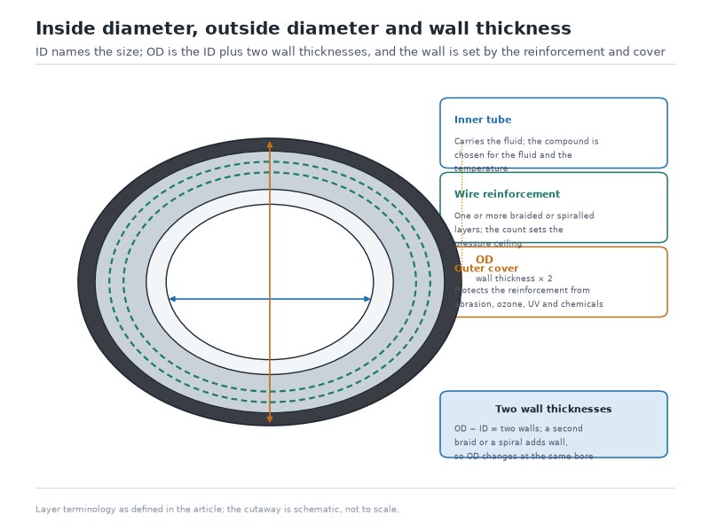
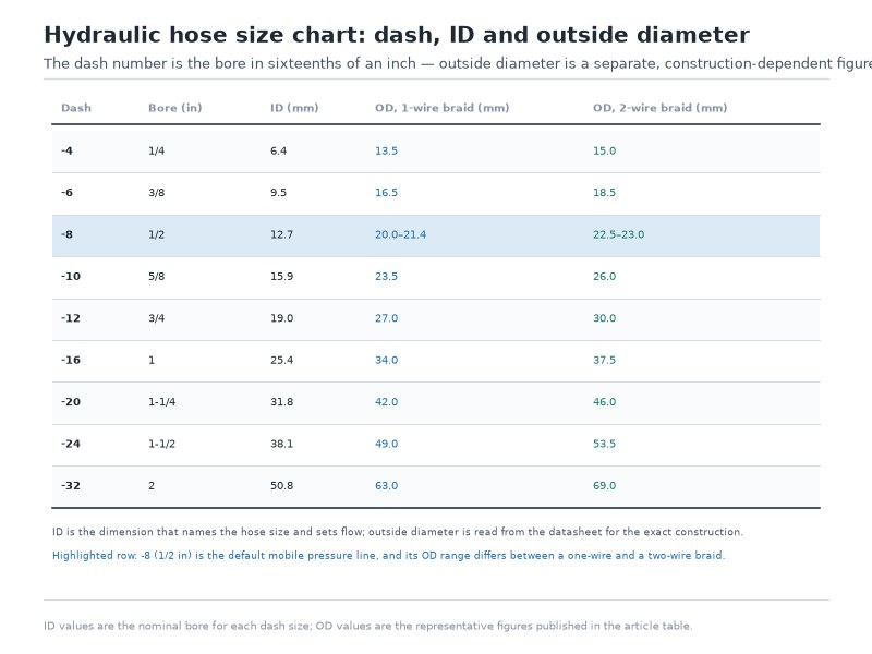
The confusion is built into the vocabulary: hydraulic hose fitting sizes are quoted against the thread, while hose sizes are quoted against the bore. A hydraulic fitting size chart is therefore only useful once you know which of the two you are measuring. To measure the hose rather than the fitting, use the outside diameter as a cross-check and the bore as the answer. A 1/2-inch (-8) bore hose measures roughly 20.0 to 21.4 mm outside on a single-wire-braid construction, 22.5 to 23.0 mm on a double-wire-braid line and 23.8 to 25.4 mm on a four-spiral high-pressure construction, so outside diameter alone cannot tell you the dash — cut a short sample and measure the bore, or read the layline. The how to measure a hydraulic hose guide covers that measurement step by step. Our types of hydraulic hose guide covers how bore, reinforcement and dash size interlock on the hose side.
7. How to Select Hydraulic Hose Fittings: Six Steps in Order
Six facts decide which ends go on an assembly, and they are collected in one order: the hose bore, the working pressure, the fluid and its temperature, the port on the machine, the routing, and the material. This section works through them in that order, starting at the machine and working back to the hose.
Step 1: Fix the Hose Bore First
The hose bore is decided by flow rate and acceptable fluid velocity, not by the port. If the port is -8 and the flow demands a -12 hose, the correct answer is a -12 hose with a -8 port end, not a -8 hose that runs the oil hot. Running a line one dash size small raises fluid velocity into the range where pressure drop and heat become the limiting factor on the machine.
Step 2: Match the Pressure, and Check the Fitting’s Own Rating
The assembly is only as strong as its weakest part. A 6,000 PSI spiral hose with a 3,000 PSI-rated fitting end is a 3,000 PSI assembly. Four points govern this step.
- Size the hose and fitting for the system working pressure, not the pump’s nominal setting — relief settings and pressure spikes both sit above steady state
- Confirm the hose meets the relation its own standard defines, in which the minimum burst pressure is four times the maximum working pressure (SAE J517 / EN 853), and confirm the fitting’s working pressure rating is at least the hose’s working pressure
- Where surge or impulse is frequent, prefer a face-seal family (ORFS) or a flange over a metal-to-metal cone
- If the hose is a SAE 100R hydraulic hose family, confirm the fitting series is approved for that hose construction
- If you are still choosing between a braided and a spiral hose body, the two-wire braid versus four-spiral comparison sets the constructions against each other before you buy ends for them
Step 3: Verify Fluid and Temperature Compatibility, Then Pick the Seal Compound
The metallic parts are almost never the problem; the elastomer is. Each seal compound has a fluid and temperature envelope, and stepping outside it produces swelling, hardening or extrusion within weeks.
Table 7. Seal and washer compounds by fluid and temperature envelope — the last column carries either a fluid to avoid or a handling note, and the values are typical industry values to confirm against the seal maker’s data for the specific fluid
| Compound | Typical temperature range | Good with | Avoid with / handling note |
|---|---|---|---|
| NBR (nitrile) | About -30°C to +100°C | Mineral hydraulic oil, water-glycol | Phosphate ester, ketones, high aromatic content |
| FKM (fluorocarbon) | About -20°C to +200°C | Phosphate ester, hot mineral oil, many solvents | Water-based fluids at high temperature, ammonia |
| EPDM | About -40°C to +150°C | Water-glycol, brake fluid, steam-adjacent service | Mineral oil and petroleum fluids |
| PTFE | About -65°C to +200°C and above | Aggressive chemicals, solvents, wide temperature swings | Not used where a soft compliant seal is needed at low load |
| Copper washer | About -50°C to +200°C | Banjo and bonded-washer joints on mineral oil | Replacement after reuse — anneal or renew |
Step 4: Identify the Port on the Machine, Then Choose the Adapter
Now read the machine: measure the port, not the old fitting. Ports get replaced, retapped and adapted, so an old fitting from a bin is not evidence of what the port actually is. This is the step where the hydraulic oil hose selection process and fitting selection meet — bore and pressure come from the system, port type comes from the hardware.
Step 5: Check Routing, Bend Radius and Orientation
A correctly rated fitting that cannot be tightened is an installation failure. Four routing questions decide the fitting geometry.
- Does the line need a 45° or 90° elbow to clear the structure, or will a straight end do?
- Will a swivel nut let the assembly be oriented after tightening, or is the line going to be twisted?
- Is there enough straight length after the fitting for the hose to bend without kinking?
- Does the routing used on an excavator boom style of protection — sleeving at contact points — apply here?
Step 6: Choose the Material and Finish for the Environment
Carbon steel with zinc plating covers most indoor and mobile duty. Washdown, marine, offshore and chemical exposure move the decision to stainless. Deicing salt and fertiliser environments sit between the two, and are the case where a zinc-nickel or stainless upgrade usually pays for itself in avoided replacements. Where the line is carrying petroleum-based fluid in wet or salt-laden conditions, the tube and cover compound matters as much as the fitting — the same corrosion logic behind oil-resistant hose selection applies to the ends.
Selection Checklist: What to Send a Supplier
Copy this list into a quote request and most suppliers can price the job from a single message.
What the line has to do
- Hose bore or dash size, and the length required, including fitting allowance
- Hose construction or SAE/EN family, if known, plus the layline text if not
- System working pressure, and peak or surge pressure if the circuit is shock-loaded
- Fluid type and the maximum and minimum operating temperature
- Port end at each side: family, thread size, male or female, straight, 45° or 90°
What the order has to carry
- Hydraulic hose ends required at each side: crimped or reusable
- Fitting material and finish required
- Quantity, required delivery date, and whether a test report or sample is needed
- Any standard the assembly must meet, and whether the machine is subject to third-party inspection
Send the checklist above — family, dash size, material, quantity, annual volume and documentation — and our engineers will return a cost-and-lead-time band. Request a quote and free samples.
8. Steel, Stainless or Brass? Choosing the Fitting Material
Fitting material is a corrosion decision first and a pressure decision second. Strength grades of carbon steel and stainless are both adequate for the great majority of hydraulic circuits; what differs is how long they survive the environment and how they behave against the mating part.
Table 8. Hydraulic hose fitting material comparison
| Material | Corrosion resistance | Relative cost | Typical use | Caution |
|---|---|---|---|---|
| Carbon steel, zinc-plated | Moderate — adequate for indoor and dry mobile duty | Baseline | General mobile and industrial equipment | Plating wears at abrasion points and rust follows |
| Carbon steel, zinc-nickel | Good — salt-spray resistant | Modest premium over zinc | Agricultural, construction, winter road equipment | Confirm coating thickness on the data sheet |
| Stainless steel 316 | High — marine and chemical service | Substantially higher | Offshore, marine deck machinery, food and pharma, washdown | Prone to galling against stainless threads — use an anti-seize rated for the duty |
| Brass | Good in water and air, moderate in hydraulic oil | Low to moderate | Low-pressure circuits, instrumentation, air and water pilot lines | Not for high pressure; softer threads deform if over-tightened |
Galling deserves a specific warning. Two stainless parts threaded together under load can cold-weld and become inseparable, and we have seen this take a cylinder out of service for a full shift. Anti-seize is not optional on stainless-to-stainless joints in wet or high-temperature duty.
9. How Do Hydraulic Hose Fittings Fail?
Fittings fail in a small number of predictable ways, and almost none of them are manufacturing defects. Knowing the pattern makes a leak diagnosable in minutes instead of a parts-guessing exercise.
At the joint itself
- Cross-family assembly on a matching thread. JIC male into an ORB port, or BSPT into NPT. The joint tightens, holds briefly at low pressure and weeps as soon as the system warms up.
- O-ring degradation. Heat, wrong compound for the fluid, or a nicked O-ring on install. The seal hardens, loses compression set and stops sealing.
- Over-torque. The cone or face deforms, the thread stretches, or the O-ring extrudes. Over-torqued joints frequently leak worse than correctly torqued ones.
- Under-torque. Vibration backs the nut off and the joint loses preload. The classic signature is a fitting that weeps only at certain engine speeds.
Behind the joint
- Fitting pull-off. A ferrule that does not match the hose construction, an incorrect crimp diameter, or a reusable fitting used past its pressure limit. This is the failure that turns a leak into an injury.
- Galling and thread seizure. Stainless-to-stainless joints, or a joint left under load in a corrosive environment.
- Corrosion under the plating. Rust lifts the plating, the thread diameter changes and the joint loses preload.
- Seat damage from debris. A metal particle or a piece of thread sealant sits on the cone or the flat face and holds the joint slightly open.
What to Inspect, and When to Replace
Check these points at each service interval, and immediately after any hydraulic repair:
- Any wet film, droplet or staining at the nut-to-port junction
- Exposed or fretted thread on the fitting body, which indicates it has been loose
- O-ring hardness — a seal that has lost its compliance will not reseal even if re-tightened
- Rust bloom or plating loss on the fitting body and on the adapter
- Hose cover damage within two bore diameters of the fitting, where bending stress concentrates
- Mark or scribe line on the nut, which lets you confirm it has not rotated since installation
The honest limitation to state here: fittings do not have a published service life the way a hose layline date does. Replacement is condition-based. Once an O-ring or a cone seat has leaked, the correct action is to replace the seal element and the fitting if the seat is marked — re-tightening is a temporary measure that usually fails again under load.
10. How Much Do Hydraulic Hose Fittings Cost?
Fitting price is driven by family, size, material and volume, in that order. The table below gives planning bands per fitting, not quotations; the spread within a single line comes from size and material.
Table 9. Typical hydraulic hose fitting cost bands by family and size (planning bands for volume purchase, not quotations)
| Family | Small sizes, -4 to -8 | Mid sizes, -10 to -16 | Large sizes, -20 and up | Cost driver |
|---|---|---|---|---|
| JIC 37° flare, carbon steel | Lowest band | Low to mid band | Mid band | Plain machining, minimal components |
| ORFS face seal, carbon steel | Low to mid band | Mid band | Mid to high band | Groove machining plus O-ring |
| ORB, carbon steel | Low to mid band | Mid band | Mid band | O-ring and washer, boss machining |
| NPT, carbon steel | Lowest band | Low band | Low to mid band | Simple tapered thread |
| BSPP / BSPT, carbon steel | Low to mid band | Mid band | Mid band | Whitworth thread, bonded washer |
| Metric 24° cone, carbon steel | Low to mid band | Mid band | Mid band | Cone seat machining, light versus heavy series |
| SAE flange, carbon steel | Not common | Mid to high band | High band | Four-bolt head, O-ring, often split flange kits |
| Any family, stainless 316 | Two to four times carbon steel | Two to four times carbon steel | Two to four times carbon steel | Material cost and slower machining |
Four commercial factors move the price more than the fitting itself:
- Assembly versus component. A crimped assembly includes the hose, two fittings and the crimping labour. Buyers comparing a bare fitting price against an assembled line price are comparing two different products.
- Crimp tooling. Non-standard fitting and hose combinations may need a dedicated die, which is a one-off cost. Standard combinations avoid it entirely.
- Order quantity and stock coverage. Fast-moving dash sizes in JIC and ORFS are usually stocked; a run of metric heavy-series ends in stainless is often made to order and carries a longer lead time.
- Documentation. Test reports, material certificates and third-party inspection add cost but are frequently mandatory for offshore, mining and food-industry buyers.
The cost bands in Table 9 are relative to JIC carbon steel in the same size range, which sets the baseline; stainless 316 is the only row quoted as a multiplier.
Send the family, dash size, material, quantity and annual volume, and we will return a cost-and-lead-time band for the exact mix — including whether a stocked size can avoid a dedicated die.
11. Assembly and Torque: Getting the Joint Right the First Time
Whether the hydraulic hose ends are crimped or reusable, two variables decide whether the assembly performs: crimp quality and torque discipline. Both are under the buyer’s control after the parts arrive.
On the crimp: use the fitting manufacturer’s published crimp specification for that exact hose and fitting combination, and measure the crimped diameter after every setup change. A crimp that is 0.2 mm under target can cut the reinforcement; one that is 0.2 mm over can allow the fitting to pull off. We measure the crimp diameter on a sample from each production batch rather than relying on the press setting alone.
Two safety rules apply whenever a circuit is opened. Relieve stored pressure and isolate the machine before loosening any connection, because accumulators and raised implements hold pressure with the pump off. And locate a suspected high-pressure leak with a sheet of cardboard rather than a hand: a pinhole jet can inject fluid through skin without pain at the moment of injury, and an injection injury is a surgical emergency.
On the torque: threaded fittings are torqued to a published value for their thread size, not “as tight as it goes.” The values below are planning bands for clean, dry threads on zinc-plated steel; a lubricated thread reaches the same preload at a lower wrench reading, so always prefer the fitting maker’s own table for the exact part where you have it.
Table 10. Typical assembly torque bands for ORFS and ORB hose end fittings by dash size and thread
| Strichstärke | ORFS thread | ORFS torque (ft-lb) | ORFS torque (N·m) | ORB thread | ORB torque (ft-lb) | ORB torque (N·m) |
|---|---|---|---|---|---|---|
| -4 | 9/16-18 | 14-16 | 19-22 | 7/16-20 | 12-14 | 16-19 |
| -6 | 11/16-16 | 18-20 | 24-27 | 9/16-18 | 18-20 | 24-27 |
| -8 | 13/16-16 | 32-35 | 43-48 | 3/4-16 | 34-36 | 46-49 |
| -10 | 1-14 | 42-46 | 57-62 | 7/8-14 | 46-50 | 62-68 |
| -12 | 1 3/16-12 | 60-65 | 81-88 | 1 1/16-12 | 65-70 | 88-95 |
| -16 | 1 7/16-12 | 95-100 | 129-136 | 1 5/16-12 | 92-100 | 125-136 |
| -20 | 1 11/16-12 | 125-140 | 170-190 | 1 5/8-12 | 125-140 | 170-190 |
These are planning bands for clean, dry threads on zinc-plated steel. The fitting manufacturer’s table for the exact part governs, because plating, lubrication and material all move the number. The ORFS bands are the same ones published in our the thread and seal data for those families, so the two pages can be quoted together.
Three practical rules that prevent most assembly faults:
- Never use thread sealant on a face-seal or cone-seal fitting. Sealant on an ORFS or JIC thread contaminates the seal and can migrate into the system.
- Hold the mating part, not the hose. Torquing against a hose twists the reinforcement and shortens assembly life.
- Tighten, mark, and re-check after the first heat cycle. Thermal cycling relaxes preload on some joints, and a scribe mark makes movement visible at the next inspection.
12. JIC vs SAE, NPT vs BSP, ORFS vs JIC: The Comparisons Buyers Search For
Three comparisons account for most of the questions buyers ask, and all three turn on the same principle: a shared thread does not mean a shared seal. The JIC vs SAE fittings question is really a question about cone angle. NPT vs BSP is about thread angle and taper. ORFS vs JIC is about which family earns its cost in a given duty. Each family described above appears in at least one of these comparisons.
JIC vs SAE Fittings: Are They the Same Thing?
They are related but not identical, and the confusion is entirely nominal. JIC is a 37° flare standard published as SAE J514, so a JIC fitting *is* an SAE fitting in the sense that it is governed by an SAE standard. What people usually mean when they say “SAE fittings” is SAE 45° flare, published as SAE J512, which uses a 45° cone instead of 37°.
The practical difference is the cone angle and the interchange risk, so treat the JIC vs SAE fittings question as a seat-angle question first and let the thread confirm it. A 37° and a 45° flare will often screw together and will not seal reliably, because the cone contacts on a line rather than a face. Use the thread as the identifier: 9/16-18 is JIC 37°, while 5/8-18 is SAE 45° flare. SAE 45° is overwhelmingly found on automotive and older equipment; JIC 37° is the mobile and industrial hydraulic standard. If you stock both, catalogue them by thread rather than by the JIC vs SAE fittings label, because the label is where the ordering errors start.
NPT vs BSP: Two Pipe Threads That Share Sizes
NPT and BSP share size names and, at 1/2 inch, share a thread count of 14. They differ in three ways that matter.
Table 11. NPT versus BSP pipe threads
| Property | NPT / NPTF | BSPP / BSPT |
|---|---|---|
| Thread angle | 60° | 55° |
| Standard | ASME B1.20.1, SAE J476 | ISO 228-1 (parallel), ISO 7-1 (tapered) |
| Forms | Tapered; NPTF is the dryseal version | Parallel (BSPP/G) and tapered (BSPT/R) |
| Sealing method | Thread interference, sealant usually required on NPT | Bonded washer on a flat face or 60° cone seat for BSPP; thread interference for BSPT |
| Thread counts at 1/4, 1/2, 1 inch | 18, 14, 11.5 TPI | 19, 14, 11 TPI |
The 1/4-inch size is the cleanest separator: 18 TPI is NPT, 19 TPI is BSP. If you are working on European or Japanese machinery, assume BSP until the pitch gauge says otherwise.
ORFS vs JIC: Which Should You Specify?
Table 12. Choosing between ORFS and JIC by application condition
| Application signal | Better choice |
|---|---|
| Working pressure above the JIC band for that size — about 6,000 PSI at the smallest sizes, about 3,000 PSI at -16 and above | ORFS |
| Frequent pressure spikes or impulse duty | ORFS |
| System temperature above the NBR range | ORFS with an FKM O-ring |
| Frequent assembly and disassembly in the field | JIC — no elastomer to lose or damage |
| Very high ambient heat at the joint | JIC, where the metal-to-metal cone survives what an O-ring does not |
| Lowest cost in a medium-pressure circuit | JIC |
Neither is universally better. ORFS holds more pressure and seals more reliably against minor seat damage; JIC has one fewer wear item and tolerates heat better. We supply both in matched assemblies and specify JIC on medium-pressure mobile lines and ORFS above roughly 3,000 PSI or wherever impulse life drives the design.
13. Frequently Asked Questions
How do I identify a hydraulic hose fitting?
Measure the thread outside diameter with a caliper, count the threads per inch or read the metric pitch, check whether the thread is straight or tapered, then look at the sealing face. Those four readings place the fitting in one of eight families. This is how to identify hydraulic fittings by measurement rather than by eye, and it is more reliable than visual matching: thread size and threads per inch identify the thread standard, while the sealing face identifies the family and tells you what will actually seal. A photograph beside a steel rule is usually enough for a supplier to confirm hydraulic hose fitting identification before quoting.
How many types of hydraulic hose fittings are there?
Counted by the way they seal, eight end-connection families cover almost every machine: JIC 37° flare, ORFS, ORB, NPT and NPTF, BSPP, BSPT, metric 24° cone and SAE flange. Counted by the job they do rather than by the seal, the same parts split again into hose ends, adapters and quick couplings. Use the eight-family answer at the bench, because the family tells you what will seal, while the job title only tells you where the part sits in the system.
What is a hydraulic hose ferrule, and when does it need replacing?
The ferrule — also called the socket or the shell — is the collar that is crimped over the hose cover and reinforcement to lock the insert in place. It is matched to one hose construction and one crimp diameter, which makes it the part that decides whether the joint survives pressure. Fit a new ferrule with every new assembly: a ferrule is not reusable, and a pull-off at working pressure is the failure that turns a leak into an injury.
What is the difference between NPT and BSP threads?
NPT has a 60° thread angle; BSP has a 55° Whitworth thread angle. NPT is tapered in its standard form, while BSP exists in both a parallel form (BSPP) and a tapered form (BSPT). They share size names and sometimes share a thread count, which is why a pitch gauge is the fastest way to tell them apart on the bench.
How do dash sizes differ between hose sizes and hydraulic hose fitting sizes?
For the hose, the dash number is the nominal bore in sixteenths of an inch, so a -8 hose has a 1/2-inch bore. For the fitting, the same dash number indexes the thread, so a -8 JIC end is a 3/4-16 thread. The two figures are related by convention inside a family, never by value, which is why hydraulic hose fitting sizes cannot be read straight across from hose sizes and a chart is needed for the conversion.
How do I know what pressure a hydraulic hose fitting is rated for?
From the manufacturer’s table for that family, size and material — not from the fitting itself. Fittings are rated by family rather than individually, and the rating falls as the thread size grows. Published carbon steel ratings run from about 6,000 PSI in the smallest sizes down to about 3,000 PSI at -16 and above for JIC, around 6,000 PSI for ORFS and ORB, and about 3,000 PSI for Code 61 flanges against about 6,000 PSI for Code 62. The assembly rating is the lower of the hose and the fitting rating.
Why does a fitting leak only when the oil is hot?
Heat does two things at the same time: the fluid thins, so it finds any path the seal has left open, and the metal parts expand at different rates, so preload changes. A joint that is marginally under-torqued, or one relying on an O-ring that has already taken a compression set, holds cold and weeps warm. Re-tightening rarely settles it — measure the joint, fit a new seal element of the correct compound, and torque to the published band.
What wrench size do I need for hydraulic hose fittings?
Hex sizes are set by the fitting manufacturer rather than by the standards, so they differ between producers and between a hose end, a bulkhead adapter and a stud end carrying the same thread. Measure the hex across the flats with a caliper and match it to your wrench set, or read the hex dimension from the catalogue entry for the exact part number. Buying a wrench from the dash size alone will be one size wrong often enough to matter.
Where are quick connect hydraulic fittings used?
Quick connect couplings are used wherever a line is meant to be connected and disconnected as part of the job — implement circuits on a loader, attachment lines on a carrier, and service ports on a test bench. They do not replace the hose end connection: a coupler sits on the end of an adapter or a hose end, and the seal inside it is a separate wear item that belongs on the same inspection list as the rest of the circuit.
How do I identify a metric fitting on a machine I cannot remove?
Read the pitch before the diameter: metric is the only common family whose thread is measured in millimetres, so a gauge that seats at 1.5 mm or 2.0 mm settles the question even when the caliper reading is ambiguous. On an assembled machine, measure the mating adapter or the port rather than the fitting itself, then confirm the seal feature — a 24° cone with a cutting ring is DIN 2353, an O-ring under the hex is the ISO 6149 metric port.
What should come with a batch of hose fittings?
For standard industrial work, a packing list with part numbers, quantities and heat or batch references is normally enough. Ask for more when the assembly goes into offshore, mining or food-industry service: a proof-test record for each assembly, a material certificate for the fittings and a plating or coating thickness callout are the three documents most often requested at audit, and they are far easier to supply when the order is placed than years later.
Do hydraulic fittings have a shelf life?
Assembled fittings in steel have no meaningful shelf life if stored clean and dry. The elastomeric components do: O-rings and bonded washers age, harden and take a set over years of storage, particularly in hot or ozone-rich environments. Store seals in a sealed bag away from sunlight and heat, and treat aged seals as suspect regardless of appearance.
14. Final Verdict: Identify the Thread, Then the Seal, Then Verify the Manufacturer
Identifying hydraulic hose fittings is a measurement task, and selection is a sequence. Measure the thread outside diameter, the threads per inch or metric pitch, the straight-or-tapered form, and the sealing face; that places any of the types of hydraulic hose fittings into one of eight families. Then work back from the machine — hose bore, working pressure, fluid and temperature, port type, routing and material — and specify both the hose end and the port end separately.
The genuinely difficult part is not identification. It is buying the right assembly with the right crimp, in the right material, with documentation that survives an audit. That is where a manufacturer’s own process control shows up in your maintenance costs, and it is worth asking any supplier to demonstrate it before you commit to a program.
*HENGHUA manufactures hydraulic hose, hose fittings and assembled hydraulic lines for OEM, distribution and fleet-replacement programs.
The range covers the end connections described in this guide — the eight families set out in Section 3 — fitted to single-wire braid, double-wire braid and four- and six-spiral hose from 1/4 inch to 2 inch bore. Because we machine our own fittings, produce our own hose and crimp and proof-test every assembly in-house, we can supply the crimp specification and the test report for the actual line you receive rather than a generic data sheet.
If your specification calls for a fitting family or material combination that is not standard, send the checklist from Section 7 — family, dash size, material, quantity, annual volume, documentation — and our engineers will confirm feasibility, tooling and lead time. Request a quote and free samples.*
 English
  Spanish
  Portuguese
  French
  German
  Arabic
  Russian