

If you are holding a fitting stamped “JIC” and asking what it is, whether it fits your NPT port, or what size you need, here is the short answer: a JIC fitting is a 37-degree flared, metal-to-metal sealing hydraulic connection standardized under SAE J514 – it needs no O-ring, gasket, or thread sealant, and it is dimensionally interchangeable with AN fittings. This guide compares JIC vs NPT, JIC vs AN, and JIC vs SAE 45° flare fittings, covers ORFS and JIS, provides the full JIC fitting size chart, and shows how to measure, assemble, and troubleshoot JIC fittings in real hydraulic systems.
Who is this guide for? Three reader situations are covered throughout: maintenance technicians replacing a leaking or unknown fitting on existing equipment (see the measuring steps and the troubleshooting table below), first-time buyers matching a fitting to a hose or port for the first time (see the comparison section), and procurement engineers sourcing bulk fittings for a product line (see the FAQs). Each section answers one question on its own, so you can jump straight to the part you need.
In this guide:
- How the 37° flare seal works
- JIC, NPT, AN, SAE, ORFS, and JIS compared
- JIC size chart and dash sizes
- How to measure and identify a JIC connection
- Torque, assembly, and inspection
- Troubleshooting and FAQs
What Are JIC Fittings?
JIC stands for Joint Industry Council, the group that standardized this connection for wartime hydraulic systems in the 1940s. A JIC fitting is a flared tube fitting: the male half carries a cone machined at exactly 37 degrees, and a flared tube end is pressed against that cone by a threaded nut. The metal-to-metal contact between flare and cone is the entire seal – no O-ring, gasket, washer, or sealant is involved.
JIC fittings are defined by the SAE J514 standard (the Society of Automotive Engineers specification for flared tube fittings), which sets thread sizes, dash sizes, flare angle, and dimensional tolerances; the same geometry is published internationally as ISO 8434-2. The military counterpart, made to MIL-F-5509 and AS33514 specifications, is the AN (Army-Navy) fitting – dimensionally the same connection with tighter tolerances.
What are JIC fittings used for? In practice, you will find JIC hydraulic fittings wherever fluid is transferred at pressure: construction and agricultural machinery, machine tools, mobile hydraulics, marine systems, oil and gas equipment, and aerospace lines where the AN variant is standard. JIC female swivel ends are especially common on hydraulic hose assemblies, because the swivel nut turns independently and prevents the hose from twisting during installation.
A genuine JIC fitting has all three characteristics: a 37-degree cone on the male end, straight (parallel) UNF threads – never tapered, and a metal-to-metal seal at the flare, not on the threads. If any of the three is missing, treat the part as non-JIC, no matter what it is called in the catalog.
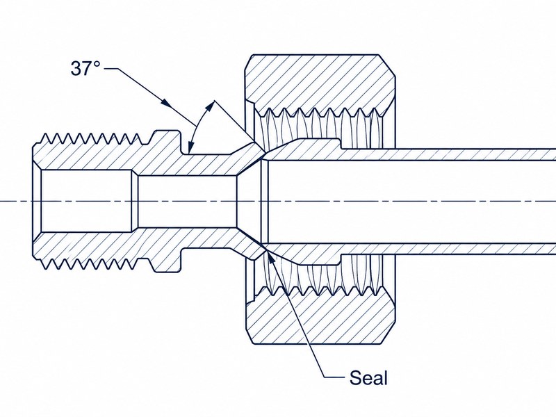
Figure 1. Cutaway of the flare joint: torque on the nut is converted into clamping force on the flare.
How Do JIC Fittings Work? The 37° Flare Seal Explained
The sealing principle is purely mechanical. A tube is flared outward at 37 degrees with a flare tool; the nut slides over the flare; when the nut is tightened onto the male body, its internal 37-degree cone presses the flare evenly against the male cone. Torque is converted into radial clamping force, and the two conical surfaces deform elastically to close the microscopic leak path.
The threads do none of the sealing. JIC threads are straight UNF (Unified National Fine) threads whose only job is to pull the nut down and hold it. That is why the same flare joint works at pressures where a straight thread alone would leak instantly – and why a scratched cone or a damaged flare leaks even with the nut fully tight.
In our production and test shop, we pressure-cycle JIC assemblies daily at their rated pressure. The seal holds only when both the cone and the flare are clean, concentric, and undamaged. A burr the size of a grain of sand is enough to produce a weep that no amount of torque will stop.
JIC vs NPT, AN, SAE, ORFS, and JIS Fittings: How to Tell Them Apart
JIC connections are frequently confused with five other hydraulic connection families, and the cost of a wrong match is a leaking system or a damaged port. The comparison below is the fastest way to tell them apart.
| Fitting type | Seal mechanism | Thread form | Sealant / O-ring? | Interchangeable with JIC? |
|---|---|---|---|---|
| JIC (SAE J514) | 37-degree flare, metal-to-metal | UNF liso | None needed | – |
| NPT | Tapered thread interference | Tapered NPT | PTFE tape or pipe dope | Não |
| AN (MIL-F-5509 / AS33514) | 37° flare, metal-to-metal | UNF liso | None needed | Yes, dimensionally |
| SAE 45° flare (SAE J512) | 45-degree flare, metal-to-metal | Heterossexual | None needed | Não |
| ORFS (SAE J1453) | O-ring face seal | UNF liso | O-ring | Não |
| JIS (JIS B8363) | 60-degree cone seat | 60° seat | None needed | Não |
Beyond JIC, NPT, AN, SAE 45° flare, ORFS, and JIS, the British BSPP and BSPT threads (55-degree thread angle) form another family common on European equipment. Metric threads, 55-degree threads, and JIC threads will never match, so verify the standard before ordering anything. If your machine has a JIC port but the new hose end is BSP, you need a purpose-made adapter that converts between the two thread families – never force a BSP end into a JIC port. In Europe, the other family you will meet is the DIN 2353 (ISO 8434-1) 24-degree cone fitting with metric threads and an O-ring or cutting-ring seal – a different sealing geometry that never matches the 37-degree JIC flare. The JIS 60-degree seat also has an international twin, ISO 8434-4, so a JIS fitting may be labeled either way.
Can I Connect a JIC Fitting to NPT?
Can I connect a JIC hose assembly directly to an NPT port on my pump, or do I need an adapter? You need an adapter – the two connections are built around different sealing principles. The JIC vs NPT difference comes down to one question: where does the seal happen? NPT (National Pipe Taper) seals by wedging tapered threads against each other, and it normally needs thread sealant to close the spiral leak path. JIC seals at the flare, so its threads are straight and need no sealant at all.
JIC and NPT fittings are not interchangeable. A male JIC fitting will not seal in an NPT port because the threads do not wedge, and a male NPT will not seal against a JIC cone because the taper changes the pitch engagement. The practical answer to the JIC vs NPT question is simple: connect them only through a purpose-made JIC to NPT adapter, never by forcing the connection – see our pipe thread compatibility guide for a full breakdown of the NPT family.
For anyone comparing JIC vs NPT fittings on a workbench, the taper check in the measuring section below settles the question in seconds.
JIC vs AN Fittings: Are They Interchangeable?
Are AN fittings the same size as JIC, and can I mix them on the same machine without leaking? AN (Army-Navy) fittings are the military version of the same 37-degree flare connection, made to military specifications. The JIC vs AN comparison usually comes down to tolerance class rather than fit: the flare angle, the thread series, and the dash sizes are identical, which is why AN and JIC parts are physically interchangeable in the vast majority of hydraulic circuits.
In practice, the JIC vs AN question rarely matters dimensionally – the parts mate and seal. The real differences are tolerance and traceability: AN parts are machined to tighter dimensional limits, are usually carbon steel, and carry MS or AS part numbers, while JIC parts are built to commercial production tolerances. Before mixing them, confirm the pressure rating and material of both halves – a match in geometry is not a guarantee of a match in rating.
What Is the Difference Between 37° and 45° Flare Fittings?
What is the difference between a 37-degree and a 45-degree flare fitting, and what happens if I force them together? “SAE fitting” is an ambiguous term, and it is the most common source of ordering errors. SAE J512 defines the SAE 45° flare fittings used in automotive fuel lines, cooling systems, and refrigeration – a different standard from the JIC flare. Both are flared, straight-thread connections, and they look similar at a glance, but the cone angles are different.
Confirm the flare angle with a flare angle gauge (also called a flare gauge) before assembly; use only matching angles – 37° with 37°, 45° with 45°. Forcing a 37-degree flare into a 45-degree cone, or the reverse, damages both parts and leaks immediately. The JIC vs SAE confusion is the most common reason we see 37° and 45° parts mixed into one return box – fittings that looked right by eye but never sealed.
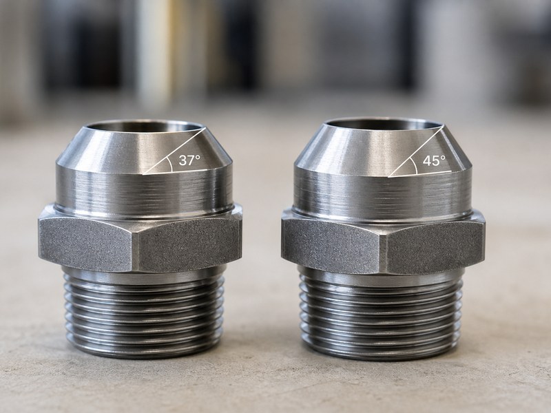
Figure 2. The 37-degree JIC cone (left) and the 45-degree SAE cone (right) look alike until they are measured.
JIC vs ORFS and ORB Fittings: When Face Seals Win
When should I choose ORFS instead of JIC for a high-vibration hydraulic circuit that gets serviced every week? ORFS (O-ring face seal, SAE J1453) seals on a flat face with an O-ring captured between two machined surfaces. Because the O-ring absorbs vibration and the flat face tolerates repeated assembly, ORFS is the better choice for high-pressure, high-vibration, and frequently serviced connections. It is not interchangeable with JIC: the geometry is completely different.
ORB (O-ring boss, SAE J1926) is a straight-thread port fitting that seals with an O-ring at the port face. It is common on pump fittings and adapters and is the closest straight-thread relative to JIC in function – but again, the sealing geometry differs, so a JIC fitting cannot replace an ORB fitting without an adapter.
Are JIC and JIS Fittings Interchangeable? (The 60° Cone)
I am replacing hydraulic hoses on a Komatsu excavator and the old fittings have a 60-degree seat – are these JIC or JIS fittings? JIS fittings, defined by JIS B8363 (Japanese Industrial Standard for 60-degree cone fittings), use a 60-degree cone seat and are standard on Japanese-built excavators and construction machinery. JIS B8363 fittings are also known in the field as the Komatsu-type cone seat – the 60-degree seat used on most Japanese excavator and construction lines. JIC and JIS fittings are not interchangeable even though both are metal-to-metal flare connections. When working on Komatsu, Hitachi, or Kobelco equipment, check the seat angle before ordering replacement fittings.
What Size JIC Fitting Do I Need? (Size Chart)
The dash number tells you the tube outside diameter in sixteenths of an inch – JIC fittings are sized by tube OD, so a -4 fitting fits 1/4-inch tube, a -8 fitting fits 1/2-inch tube. The JIC fitting size chart below covers the full SAE J514 range from -2 to -32, including JIC thread dimensions and typical wrench sizes.
| Tamanho do traço | Tube OD (in) | Tamanho da rosca | Roscas por polegada | Typical Wrench (in) |
|---|---|---|---|---|
| -2 | 1/8 | 5/16-24 UNF | 24 | 7/16 |
| -3 | 3/16 | 3/8-24 UNF | 24 | 1/2 |
| -4 | 1/4 | 7/16-20 UNF | 20 | 9/16 |
| -5 | 5/16 | 1/2-20 UNF | 20 | 5/8 |
| -6 | 3/8 | 16 a 18 de setembro – UNF | 18 | 3/4 |
| -8 | 1/2 | 3/4-16 UNF | 16 | 15/16 |
| -10 | 5/8 | 7/8-14 UNF | 14 | 1-1/8 |
| -12 | 3/4 | 1-1/16-12 UNF | 12 | 1-5/16 |
| -14 | 7/8 | 1-3/16-12 UNF | 12 | 1-7/16 |
| -16 | 1 | 1-5/16-12 UNF | 12 | 1-5/8 |
| -20 | 1-1/4 | 1-5/8-12 UNF | 12 | 1-7/8 |
| -24 | 1-1/2 | 1-7/8-12 UN | 12 | 2-1/4 |
| -32 | 2 | 2-1/2-12 UN | 12 | 2-3/4 |
Three notes from our warehouse apply to the JIC fitting size chart above. First, sizes -2 through -20 use the UNF (fine) thread series, while -24 and -32 step up to the 12-pitch UN series. Second, the wrench sizes listed in the chart are typical flat-to-flat values and do vary between manufacturers – check the datasheet of the fitting you actually bought. Third, the number always refers to the tube OD, not the thread size: a -6 fitting uses a 9/16-inch thread on 3/8-inch tube, which surprises almost every first-time buyer. Confirm the dash size and thread series on the fitting datasheet before ordering – charts are a reference, not a substitute for the part’s own data.
Need these sizes in stock? Browse our JIC fittings collection to check availability and request a quote.
How to Measure and Identify JIC Fittings
I found a fitting stamped “JIC” on my excavator’s hydraulic line – how can I tell what size it is and whether it will fit my existing hose? Identifying a JIC fitting takes about two minutes with a caliper, a thread pitch gauge, and a flare angle gauge. We use this five-step sequence whenever a customer sends an unmarked fitting or a photo of a port.
- Measure the thread outside diameter with a caliper and match it against the JIC fitting size chart. A 7/16-inch thread is a -4; a 9/16-inch thread is a -6.
- Count the threads per inch with a pitch gauge. JIC uses the UNF series – 24, 20, 18, 16, 14, or 12 TPI for the sizes above. TPI alone does not identify a JIC fitting: 18 TPI is shared with NPT 3/8-inch and 14 TPI with NPT 1/2-inch. Match the TPI against the thread OD from step 1.
- Check for taper. JIC threads are straight and parallel; if the thread gets visibly narrower toward the end, it is NPT, not JIC.
- Measure the male cone angle with a flare gauge. A clean 37-degree fit means JIC or AN; a 45-degree fit means the automotive SAE flare; a 60-degree fit means JIS.
- Look for markings. Many fittings are stamped “JIC”, “37°”, or carry a size code; AN parts carry MS or AS part numbers.
How do I know what size JIC fitting I have? Measure the thread outside diameter with a caliper and count the TPI with a pitch gauge, then compare against the JIC fitting size chart in this guide. The dash number tells you the tube size in sixteenths of an inch – a 9/16-inch thread with 18 TPI is a -6, for example.
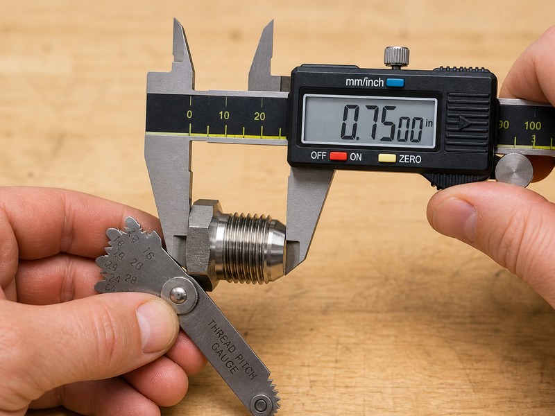
Figure 3. Thread OD plus threads per inch narrows the size; the flare gauge confirms the type.
| Check point | JIC indicates | Something else indicates |
|---|---|---|
| Thread OD | Matches chart (e.g. 7/16 in = -4) | Different series (metric, NPT) |
| Threads per inch | UNF series: 24 / 20 / 18 / 16 / 14 / 12 | TPI alone is not conclusive – 18 TPI can be JIC -6 (9/16-18) or NPT 3/8 in; 14 TPI can be JIC -10 (7/8-14) or NPT 1/2 in. Always combine TPI with the thread OD. |
| Thread taper | None – straight | Tapered = NPT or BSPT |
| Cone angle | 37 degrees (confirm with a flare angle gauge) | 45 degrees = SAE flare; 60 degrees = JIS |
| Marking | “JIC”, “37°”, or a size code | MS/AS = AN; none = verify |
Metric threads are the other common trap: metric fittings are measured in millimeters with a 60-degree thread angle, and they never match the UNF series. If your caliper reads in millimeters, the fitting is metric, not JIC – note the pitch in mm and look up the metric standard instead.
When in doubt, treat the fitting as unknown and verify with the mating equipment before ordering replacements – our how to identify hydraulic fittings guide covers NPT, BSP, and metric families in detail. A wrong guess on a hydraulic fitting is more expensive than a careful measurement. Holding something you cannot name? Send a photo to our engineering team and we will identify the connection – free of charge.
How to Identify a JIC Fitting from a Photo (What to Send a Supplier)
No caliper or gauge at hand? Use this photo workflow instead – a supplier can identify most connections from three good photos. If you can send three photos, we can usually identify the connection in one business day:
- Thread close-up: a caliper reading of the thread outside diameter (in inches or mm) in the same shot.
- Thread side view: to check whether the threads are straight (JIC) or tapered (NPT).
- Cone or seat close-up: the angle of the sealing surface, ideally with a flare gauge in place.
Add the machine or application, the system working pressure, and any markings stamped on the fitting. With those five pieces of information, a supplier can confirm the standard, dash size, and material before you order. This workflow works for JIC, NPT, ORFS, BSPP/BSPT, and metric fittings alike, and it is how our team handles most identification requests from the field.
JIC Fitting Materials, Pressure Ratings, and Thread Types
The three standard JIC fitting materials are zinc-plated carbon steel, stainless steel (304/316), and brass – choose by media, environment, and system pressure.
- Zinc-plated carbon steel is the default for general hydraulic service. It offers the best strength-to-cost ratio and is what most OEM hydraulic circuits use – see our flexible hose materials guide for how hose compounds pair with these materials.
- Stainless steel (304 and 316) is specified for corrosive media, marine environments, food and pharmaceutical lines, and applications where rust contamination is unacceptable.
- Latão is used for low-pressure air, water, and instrumentation lines where corrosion resistance matters more than strength.
What is the maximum working pressure of a -8 JIC steel fitting in a 5,000 psi system? A -8 JIC steel fitting is typically rated up to 5,000 psi, which matches a 5,000 psi system only if the hose, tube wall, and relief valve setting are all rated for the same pressure. Working pressure depends on dash size and material, not on the fitting type alone. As a general rule, JIC connections in steel are rated between 3,000 and 6,000 psi, with the smaller sizes at the top of the range and larger sizes lower, as shown in the table below.
| Tamanho do traço | Typical Working Pressure (psi, steel) |
|---|---|
| -4 | up to 6,000 |
| -6 | up to 5,500 |
| -8 | up to 5,000 |
| -10 | up to 4,500 |
| -12 | up to 4,000 |
| -16 | up to 3,000 |
| -20 | up to 2,500 |
| -24 | up to 2,000 |
| -32 | up to 1,500 |
Scope: the pressure values above apply to zinc-plated carbon steel fittings only. Stainless steel and brass ratings are different – 316 stainless is usually rated higher than brass in the same size – and ratings vary between manufacturers. Confirm the rating on the datasheet of the actual fitting against your system’s relief valve setting.
What pressure is a JIC fitting rated for? Typically 3,000 to 6,000 psi depending on dash size and material. Always check the manufacturer’s pressure rating against your system pressure before installation.
The thread types matter as much as the material. JIC threads are straight UNF; the connection seals at the flare, never on the threads. That single fact explains why PTFE tape is not only unnecessary on JIC threads but actively harmful – tape on the threads can prevent the nut from seating fully against the cone, which guarantees a leak at the flare.
Do I need to put PTFE tape on JIC threads to stop a leak at the flare? No. The seal is the metal-to-metal contact between the flare and the cone; tape on the threads prevents full seating and causes leaks at the flare. Keep JIC threads clean and dry during assembly.
How to Assemble JIC Fittings Correctly
A correct JIC assembly takes five steps, and skipping any of them shows up as a leak at the pressure test.
- Cut the tube square and deburr both the inside and outside edges. A ragged edge will damage the flare.
- Slide the nut onto the tube before flaring – with the cone facing the tube end. Forgetting this step means cutting the tube again.
- Form the flare with a 37-degree flare tool. The tool must match the dash size; an undersized flare will pull through the cone, and an oversized flare will not seat.
- Clean the cone and the flare, then seat the flare against the male cone by hand.
- Tighten with a wrench. Mark a reference line across the nut and body, then tighten to the manufacturer’s torque table for the dash size; as a working rule, most sizes take about one-eighth to one-quarter of a turn past the point where resistance builds.
Scope: this one-eighth to one-quarter turn rule applies to steel fittings in dash sizes -4 through -16. For -20 and larger, or any stainless assembly, follow the manufacturer’s torque table.
What Torque Does a JIC Flare Nut Need? (Typical Values)
The values below are typical published ranges for zinc-plated carbon steel JIC nuts in good condition. They vary between manufacturers – use them as a starting point and always confirm against the datasheet of the fitting you are installing.
| Tamanho do traço | Typical Nut Torque (ft-lb) |
|---|---|
| -4 | 10-15 |
| -6 | 20-30 |
| -8 | 35-45 |
| -10 | 45-60 |
| -12 | 60-75 |
| -16 | 90-100 |
| -20 | 115-130 |
| -24 | 140-160 |
| -32 | 200-230 |
Torque values assume clean, dry threads at room temperature. For 316 stainless steel, use the lower end of each range and apply a light anti-seize to the threads to reduce galling. Dash sizes -2, -3, -5, and -14 are not listed because they are less common in service – use the manufacturer’s torque table for those sizes.
Need the exact torque and material data for the part on your bench? Check the fitting datasheet or ask our engineering team for the matching spec sheet.
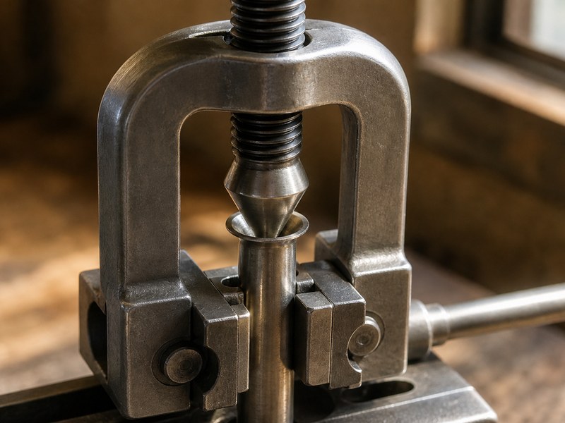
Figure 4. A correctly formed flare is the single most important variable in a leak-free JIC joint.
5-Point Flare Inspection Checklist
A flare that passes all five points will seat; a flare that fails any one of them will leak or pull through under pressure.
- Angle: the flare sits cleanly in a flare angle gauge – no rocking.
- Concentricity: the flare is uniform all the way around, with no thin or wavy sections.
- Surface: no scratches, tool marks, or cracks on the flare face.
- Size: the flare OD matches the dash size – an undersized flare will pull through the cone.
- Nut: the nut spins freely over the flare before assembly.
Two rules we enforce in our own shop. First, keep JIC threads clean and dry during assembly – the flare is the seal, and tape or pipe dope only interferes with seating. Second, a light coat of anti-seize on the threads is acceptable in steel or stainless assemblies to prevent galling, but keep it off the cone; the cone must stay clean to seal. Replace, do not reuse, any fitting with a scored cone or a work-hardened flare.
Common JIC Fitting Problems and How to Fix Them
Why does my JIC fitting leak after I retightened it, even though the nut is fully tight? Almost every JIC failure we troubleshoot in the field traces back to one of the mistakes below. Use the table as a pre-installation checklist.
| Problem | Typical cause | Correct fix |
|---|---|---|
| Leak at the flare | Damaged flare, scratched cone, or debris | Re-flare the tube; inspect and clean the cone |
| Leak after retightening | Sealant tape on threads preventing full seating | Remove tape, clean threads, re-assemble dry |
| Flare pulled through the nut | Flare formed with the wrong tool or undersized | Re-flare with the correct 37-degree tool for the dash size |
| Cracked cone or nut | Overtightening beyond the torque table | Replace the part; follow the torque table |
| Fitting loosens under vibration | Metal-to-metal flare work-hardening | Use ORFS for high-vibration circuits |
| Cross-threaded connection | Starting the nut at an angle | Start by hand; feel the threads seat before using a wrench |
| Galling on steel threads | Dry assembly under high torque | Apply anti-seize to threads only |
For a leak you cannot trace, our test bench pressure-cycles flare assemblies daily – send the assembly details and we will help pinpoint the cause.
Case 1: The 60° seat that looked like JIC. A maintenance team sent us a photo of a leaking arm line on a Japanese excavator. The adapter they had installed was JIC (37°), but the port was JIS B8363 (60°), so the cone never seated – the leak returned after every retightening. We confirmed the seat angle from the photo and supplied 60° JIS adapters; the joint sealed on the first installation. The lesson: when the seat angle and the fitting angle do not match, no amount of torque will make the joint seal.
Case 2: The tape that caused the weep. A machine shop rebuilt a manifold and wrapped every JIC thread in PTFE tape. The flare joints wept at 3,000 psi no matter the torque. The tape had stopped the nuts from seating fully against the cone; once the tape was removed, the same joints sealed dry.
How We Pressure-Test Flare Assemblies on Our Bench
Every flare assembly we ship is pressure-cycled before packing, and the same short sequence works for a shop checking its own work:
- Torque the nut to the torque value for the dash size and mark the nut-to-body reference line.
- Pressure-cycle the joint three times to the rated pressure and hold for 60 seconds.
- Wipe the flare and cone joint dry, then watch the seal line for any weep for two minutes.
- If a weep appears, re-check the flare against the 5-point checklist before re-torquing.
A joint that holds through this sequence is ready for service.
Common JIC Myths
- Myth: JIC threads need thread sealant to hold pressure. Fact: the seal is at the flare; sealant on the threads prevents full seating and causes leaks.
- Myth: AN and JIC are the same part. Fact: the geometry matches, but tolerances, materials, and traceability differ – check the pressure rating of both halves before mixing.
- Myth: Tightening harder always stops a JIC leak. Fact: over-torque cracks the cone or the nut; a damaged flare will not seal at any torque.
- Myth: Any flared fitting seals against any flare cone. Fact: 37°, 45°, and 60° cones are not compatible and must never be forced together – confirm the angle with a flare gauge first.
JIC Fitting FAQs
What does JIC stand for?
JIC stands for Joint Industry Council, the industry body that standardized the flared hydraulic connection now used around the world.
Are JIC and AN fittings the same?
Dimensionally, yes. AN fittings are the military version of the same flare connection, with identical threads and dimensions but tighter tolerances. The practical JIC vs AN difference is tolerance and traceability, not geometry – they mate and seal together in practice.
Can a JIC fitting connect to NPT?
Not directly. JIC seals on the flare with straight threads; NPT seals on tapered threads with sealant. A JIC to NPT adapter is required to convert between them.
Does a JIC fitting need PTFE tape?
No. The seal is the metal-to-metal contact between the flare and the cone. Tape on the threads prevents full seating and causes leaks at the flare.
What is the difference between 37-degree and 45-degree flare fittings?
The JIC vs SAE difference is the flare angle: JIC and AN use 37 degrees; automotive flare fittings (SAE J512) use 45 degrees. The angles are not compatible and must never be forced together.
How do I know what size JIC fitting I have?
Measure the thread OD and count the TPI, then match them against the size chart in this guide. If you have a flare angle gauge, confirm the cone is 37 degrees – the dash number tells you the tube size in sixteenths of an inch.
What pressure is a JIC fitting rated for?
Typically 3,000 to 6,000 psi depending on dash size and material. Always check the manufacturer’s pressure rating against your system pressure before installation.
When should I use ORFS instead of JIC?
Use ORFS (SAE J1453) for high-pressure circuits with heavy vibration or frequent disassembly. The O-ring absorbs vibration better than a metal flare, which can work-harden and crack.
I am sourcing JIC hose fittings in bulk for our hose assembly shop – which dash sizes and materials should we stock for general hydraulic work?
Stock the sizes that cover the majority of service calls: -4, -6, and -8 in zinc-plated carbon steel cover most mobile and industrial circuits, with -10 and -12 for larger lines. Add stainless 316 versions of the same sizes if your customers work with corrosive media, and keep brass -4 and -6 for air and instrumentation lines. Confirm pressure ratings against the circuits you actually service before placing a bulk order. Browse our fittings range to check sizes and lead times.
I’m new to hydraulic fittings and need to replace a JIC line – what’s the safest way to start?
Start by measuring the thread OD and TPI with a caliper and pitch gauge (see the measuring steps in this guide), confirm the flare angle is 37°, then match the dash size to the chart. If anything is unclear, send a photo to HENGHUA’s engineering team before ordering – a wrong guess is more expensive than a careful measurement.
How do I keep JIC joints from leaking on equipment serviced weekly?
Assemble dry, torque to the table for the dash size, and run the 5-point flare inspection before every reassembly. On high-vibration circuits serviced often, consider ORFS – its O-ring absorbs vibration better than a metal flare.
I’m sourcing bulk fittings for our product line – what should I verify before ordering?
Confirm material against media (carbon steel / 304 / 316 / brass), pressure rating against your system’s relief valve setting, tolerance class (commercial JIC vs tighter AN/MS), and traceability documentation if your product line requires it. Ask for samples and pressure-test them on your own bench before committing to a bulk quantity.
Can I use a JIC fitting on a Japanese excavator port?
Only if the port has a 37-degree seat – the JIC vs JIS difference is the seat angle. Japanese-built excavators (Komatsu, Hitachi, Kobelco) use the JIS 60-degree cone (JIS B8363 / ISO 8434-4), which a JIC 37-degree fitting will not seal against. Check the seat angle with a flare gauge, or send a photo to our engineering team before ordering.
Conclusion: Choose the Right JIC Fittings for Your System
The JIC connection is the workhorse of hydraulic systems: a metal-to-metal flare seal, straight threads, no O-rings, no sealant, and a size range that covers everything from instrument lines to 2-inch main circuits. Match the dash size to your tube, verify the flare angle with a flare gauge, assemble dry and to torque, and the joint will hold pressure for the life of the machine. Keep our hydraulic fittings size chart within reach when you are between the workshop and the catalog.
If you are sourcing JIC fittings, hydraulic hose assemblies, or adapters and want to verify the correct size and material before you buy, send us the fitting, its port, and your system pressure – we will confirm the standard, check compatibility, and quote the correct part before you spend money on the wrong one – usually within one business day.
About HENGHUA: Flare Seals We Form, Hoses We Build
HENGHUA is a manufacturer of reinforced rubber hose assemblies and threaded fittings for hydraulic and industrial fluid transfer. Every flare-type connection described in this guide is part of our standard production: flared tube fittings, swivel nuts, adapters, and crimped hose assemblies in carbon steel, stainless steel, and brass.
Flare quality is the difference between a joint that seals and one that weeps, so we form and inspect every flare against standard SAE geometry – checking the cone angle and thread dimensions before assembly. Our test bench pressure-cycles flare assemblies and checks cone seats for exactly the failure modes listed in this article’s troubleshooting table.
- Factory-direct supply – consistent pricing and lead times for distributors, OEMs, and brands.
- Full connection coverage – JIC, AN-compatible, NPT, ORFS, and BSP fittings and adapters across -2 to -32 dash sizes.
- Material options – carbon steel, stainless steel, and brass matched to your pressure rating and media.
- OEM / ODM service – custom hose lengths, end configurations, and private-label packaging for your brand.
- Engineering support – fitting identification from photos, compatibility confirmation, and sample testing before bulk orders.
Not sure whether your port is JIC, NPT, or ORFS? Send clear photos of the port and the old fitting to our engineering team – we will identify the connection and recommend the correct part, usually within one business day.
Contact the HENGHUA engineering team for a quotation or request free samples to verify the fit on your own equipment.


 English
  Spanish
  Portuguese
  French
  German