
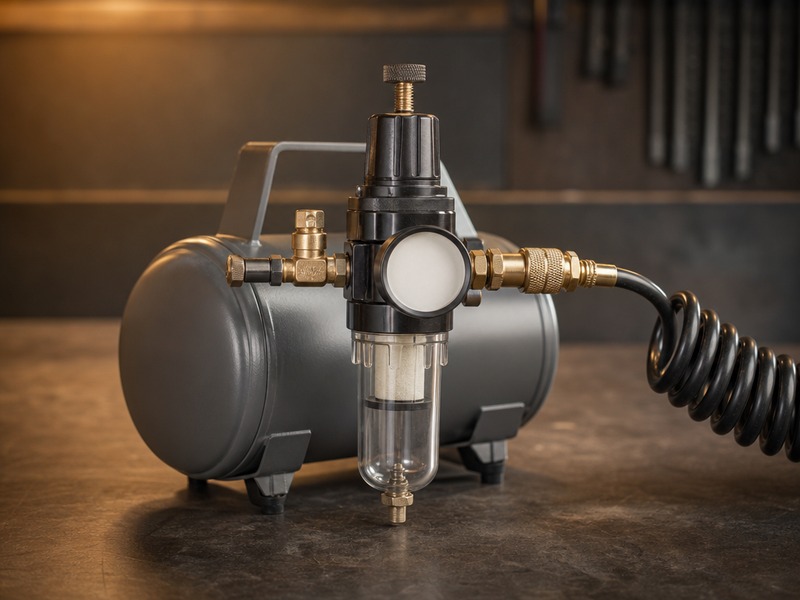
A compressor with an air regulator not working will still run and still build tank pressure, yet the tool at the end of the hose stays weak or dead. The usual cause is a worn seat or diaphragm, a supply or flow restriction, or a set point that was never verified under load.
This playbook runs from a cutaway of how a regulator works to a ten-fault symptom table and a correct adjustment procedure. It also covers the two installation mistakes behind most repeat calls, and the cases where the hose, coupler, or compressor setting is the real cause. Repair-versus-replace guidance is given for every fault, with the maintenance rules that keep a regulator serviceable.
All flow figures are our bench measurements at 100 PSI inlet and 23 °C ambient; tool demand figures are manufacturer ratings at 90 PSI. About 17 min read.
How a Pressure Regulator Works, in One Cutaway
A pressure regulator is a valve that holds an outlet pressure you choose while the inlet pressure stays higher. Air enters the inlet port at tank pressure, passes a poppet that opens and closes against a seat, and leaves through the outlet port at the set pressure. The adjusting screw loads a spring, the spring presses on a diaphragm, and the diaphragm moves the poppet. Rising outlet pressure pushes the diaphragm back and lets the poppet close.
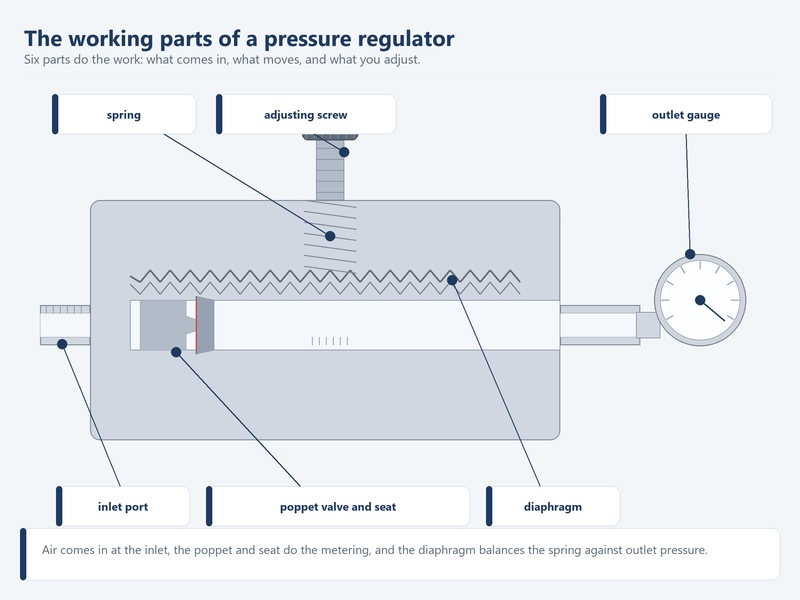
Figure 2. The working parts of a pressure regulator: inlet, poppet and seat, diaphragm, spring, adjusting screw, and outlet gauge.
The outlet gauge shows the result of that balance. A regulator is not a compressor and not a pump: it cannot create pressure the supply does not have, and it cannot pass more air than the bore ahead of it allows.
A technician hears a handful of terms on the shop floor.
Table 1. Regulator terms a technician hears, and why each one matters during a fault
| Term | Plain meaning | Why it matters in a fault |
|---|---|---|
| Set pressure | The outlet pressure you choose with the adjusting screw | Check it with no flow first, the only condition the regulator is asked to hold exactly |
| Droop | The fall in outlet pressure as flow increases | Explains a gauge that reads high at rest and lower with a tool running |
| Deadband | The pressure range between the valve opening and closing | A wide or sticky deadband makes the gauge saw up and down instead of holding |
| Cv | A flow coefficient comparing how freely a valve passes air | Used to compare regulators and couplers on restriction; it is relative, not a shop measurement |
| Flow curve | The plot of outlet pressure against flow for one regulator | Shows whether a fault is normal droop or a regulator that has failed |
| Relieving | A design that vents downstream pressure when it creeps above the set point | A short hiss after a tool stops is normal behaviour, not a leak |
| Non-relieving | A design that holds trapped downstream pressure until it is bled | Explains why pressure lingers at the tool after the supply is shut off |
The difference decides whether a noise is a fault: a relieving regulator vents air through the bonnet, so a short hiss after a tool stops is normal, while a non-relieving unit holds that trapped pressure until it is bled downstream.
Why Air Regulator Not Working Is Usually a Pressure-versus-Flow Question
A regulator is set with no air moving. The moment a tool opens, air moves, and the regulator can only hold its set point if the supply and the bore ahead of it can feed that demand. Pressure and flow are different measurements, and a gauge that reads correctly at rest can read low the instant a tool starts.
Droop is the fall in outlet pressure as flow rises through a regulator. Every regulator droops to some degree, because the spring and diaphragm must move to open the valve, and opening the valve is what costs pressure. We do not publish a droop percentage, because the figure depends on valve design, set point, and flow. What matters on the bench is the shape of the curve, not one number.
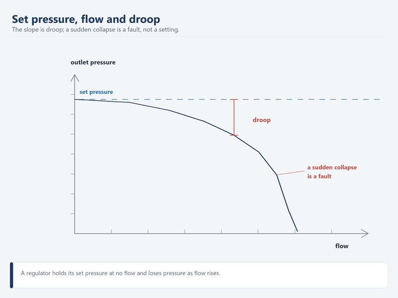
Figure 3. A regulator holds its set pressure at no flow and loses pressure as flow rises; the slope is droop, and a sudden collapse is a fault.
To confirm a real problem, run the same regulator at two flow rates, as Table 2 sets out. A regulator that holds its set point at rest and dips slightly under load is behaving as designed.
Table 2. Testing one regulator at two flow rates, and what each result means
| Stage of the test | What to do | A healthy regulator shows |
|---|---|---|
| No flow | Close the outlet valve and set the screw to the target pressure | The gauge holds the set point steadily with no tool running |
| Light flow | Open a blow gun or a brad nailer drawing 0.3 to 0.5 SCFM | A small, stable dip that recovers when the tool stops |
| Heavy flow | Open a die grinder or impact wrench drawing 4 to 8 SCFM | A visible dip that matches the flow curve, without collapse |
| Fault pattern | Compare the three readings side by side | A regulator that fails at rest, or collapses under light flow, is the fault |
That two-rate test protects against the two most expensive errors in regulator diagnosis: replacing a healthy regulator because the hose is too small, and blaming the hose because the seat has failed. Neither error is visible from the tank gauge alone. The pressure and burst-rating side of the same question is covered in our guide to air hose working pressure versus burst pressure.
Air Regulator Not Working: Ten Air Compressor Regulator Problems, Symptom by Symptom
Ten faults account for almost every regulator call in a shop. Each entry gives the likely cause, a test that takes about a minute, the fix, and whether the repair is worth doing. Work the table from the top, because the cheapest checks are also the most common causes.
Table 3. Air regulator faults 1 to 5: cause, one-minute test, fix, and repair-or-replace call
| 症状 | Likely cause | One-minute test | Fix | Repair or replace |
|---|---|---|---|---|
| Regulator will not build pressure | Adjusting screw backed fully out, failed spring or diaphragm, or inlet pressure too low | Turn the screw clockwise and watch the outlet gauge, then check the tank gauge | Confirm supply first; if supply is good, rebuild with a new diaphragm and spring | Rebuild a serviceable body; replace a crimped plastic unit |
| No outlet pressure at all | Closed isolation valve, regulator installed backwards, or a blocked filter element upstream | Open the filter drain and check for flow; check the arrow on the body | Re-pipe in the correct direction and fit a new element | Repair, because the fault is upstream of the regulator |
| Pressure creeps above the set point | Damaged or contaminated seat, or a downstream leak on a relieving unit | Close the outlet valve and watch the gauge with no tool running | Clean or replace the seat; accept a short vent on a relieving regulator | Repair; a seat kit costs far less than a new unit |
| Pressure drops when a tool is used | Flow restriction or normal droop rather than a failed regulator | Compare the regulator gauge at rest and with the tool running | Correct the bore, hose, and coupler, then reset under load | Usually no repair; treat it as a flow problem |
| Pressure drops only at the end of a long hose | Pressure drop accumulating over length and small bore | Read pressure at the regulator and again at the tool inlet | Move up one hose size or shorten the run | No regulator repair; this is system sizing |
Table 4. Air regulator faults 6 to 10: cause, one-minute test, fix, and repair-or-replace call
| 症状 | Likely cause | One-minute test | Fix | Repair or replace |
|---|---|---|---|---|
| Gauge reads correctly but tool is weak | Restriction downstream of the gauge: coupler, swivel, or undersized whip hose | Fit a gauge at the tool inlet and compare it with the regulator gauge | Replace a low-flow coupler or an undersized whip hose | Repair the restriction, not the regulator |
| Air leaks from the bonnet or screw | Ruptured diaphragm or a worn stem seal; a relieving unit venting under creep | Apply soapy water to the bonnet with the line pressurized | Replace the diaphragm and stem seal | Repair, unless the body thread is stripped |
| Air leaks from the bowl or drain | Bowl gasket, O-ring, or drain valve, often after over-tightening | Drain the bowl, then check the seals with soapy water | Replace the bowl O-ring or drain valve | Repair; these are inexpensive consumables |
| Gauge reads zero with the tank full | Broken gauge, blocked gauge port, or the regulator backed fully off | Swap in a known-good gauge, then open the screw and watch | Replace the gauge or clear the port | Repair; the gauge is the cheapest part here |
| Regulator hums or chatters | Unstable control at low flow, a fatigued spring, or pulsing from a small compressor | Open a second tool to raise flow and listen for the noise | Add downstream volume or replace the spring | Repair if it bothers operators; a chattering unit still works |
The repair-or-replace rule is simple. If the fault is a seal, spring, seat, or gauge, rebuild it, because those parts are cheap and the body is the expensive half. Replace the unit if the body is cracked, the port cross-threaded, or the housing a crimped plastic type.
How to Adjust an Air Regulator Correctly
Adjustment is where many air compressor regulator problems begin, because a regulator set without flow is not yet set for work. These steps are the ones we use on the bench:
- Isolate the regulator and relieve all downstream pressure before you touch the adjusting screw.
- Turn the screw fully counterclockwise until the outlet gauge reads zero, so you start from a known point.
- Turn the screw clockwise in small steps and watch the outlet gauge only, never the tank gauge.
- Stop at the target pressure with no flow, then wait a few seconds for the gauge to settle.
- Open the tool and read the gauge under load; if it falls too far, correct the supply or the bore, not the set point.
- Tighten the lock nut or lock ring, and re-check the same setting the next morning.
The procedure also answers the common question of how to adjust air regulator settings so the reading at the tool holds under load. Two habits separate a correct setting from a lucky one. The first is adjusting with a tool running, which leaves the regulator set high to mask droop. The second is reading the tank gauge instead of the outlet gauge, which reports receiver pressure and says nothing about the tool.
If the screw is fully in and the outlet gauge still will not reach the target, stop turning and check the supply. No amount of how to adjust air regulator pressure under load will lift an outlet above its inlet.
Two Installation Mistakes That Leave an Air Regulator Not Working
Two installation errors cause most repeat calls, and neither is a regulator fault. Both are visible in the first minute with the unit in front of you.
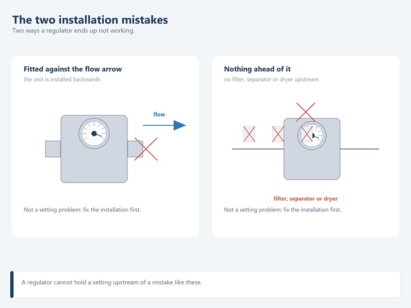
Figure 4. The two installation mistakes that make an air regulator not working: a unit facing the wrong way, and no filter, separator, or dryer ahead of it.
A regulator installed backwards
A regulator is directional, and the body carries an arrow or an IN and OUT marking showing which way the air must travel. Installed backwards, the unit may pass air at low flow and then fail to hold pressure, or hold nothing at all. Air must enter the port above the seat and leave toward the tool. If the arrow points back at the compressor, the unit is reversed and must be re-piped.
No filter, separator, or dryer upstream
Water and debris reach the seat when nothing separates them upstream, and the seat is what fails first. A filter with a drain protects the seat, and a separator or dryer keeps liquid water out of the bowl. Most air compressor regulator leaking that arrives as a service call is carryover water and grit attacking the seat, not a defective body. Compressed-air purity is classified under ISO 8573-1.
Table 5. Installation and rating mistakes, what the operator sees, and the correct practice
| Mistake | What the operator sees | Correct practice |
|---|---|---|
| Regulator fitted against the flow arrow | Weak or uncontrolled outlet pressure, or no adjustment range at all | Fit the unit so air enters the port above the seat, and check the body arrow before piping |
| No filter or separator upstream | Water and grit in the bowl, then a weeping seat | Fit a filter with a drain ahead of the regulator and empty it on a schedule |
| Filter element never changed | Falling flow and a rising regulator pressure drop across the filter | Replace the element on the maker’s interval, not only when it finally blocks |
| Regulator rated below the line pressure | A body weep or a seal that fails under load | Match the regulator’s rated inlet pressure to the supply; a 150 to 300 PSI body is not a 500 PSI body |
A reversed body and a missing filter are both cheap to fix and expensive to miss.
When the Air Regulator Is Not the Fault: Hose, Couplers, and Supply
A weak tool is often blamed on an air regulator not working when the real limit sits elsewhere in the air path. Four suspects sit between the regulator and the tool: an undersized hose, a restrictive coupler, a compressor that cuts out too low, and a loaded filter element. Each one lowers pressure at the tool without moving the regulator gauge.
The flow side of the equation is easy to picture. On our bench at 100 PSI, a 1/4 in hose passes about 40 SCFM, a 3/8 in hose about 80 SCFM, and a 1/2 in hose about 140 SCFM.
Tool demand is far smaller when a tool runs alone: a brad nailer draws 0.3 to 0.5 SCFM, a framing nailer 2.0 to 2.5 SCFM, and an air ratchet 2 to 4 SCFM. The limit is rarely the ceiling but the regulator pressure drop that builds along a long run with a hungry tool at the far end. A 1/2 in impact wrench draws 4 to 8 SCFM in short bursts, so every restriction in the path shows up under load.
Table 6. When the regulator is innocent: symptom, what to check, and the correct fix
| 症状 | What to check | Correct fix |
|---|---|---|
| Every tool on every drop is weak | Compressor cut-in and cut-out settings, and a leaking header | Reset the pressure switch so the receiver stays above the 90 PSI rate of most air tools |
| One tool is weak on one drop | The coupler and whip hose at that drop | Fit a higher-flow coupler or a larger whip hose |
| Tools weaken as hose length grows | Hose bore over the whole run | Step up one size, and check the run against the size chart |
| Flow falls off slowly over weeks | A filter element loading up and reducing flow | Replace the element and drain the separator |
| Weak only in cold weather | Stiffened hose and cold-hardened seals | Fit a cold-rated hose and fresh seals, not a bigger regulator |
Two checks settle most of these cases. First, run a leak survey, because a leaking shop loses pressure everywhere and the regulator is blamed by default; the method is in our air hose leak repair guide. Second, match the hose to the tool with what size air hose you need and the エアホースのサイズ表.
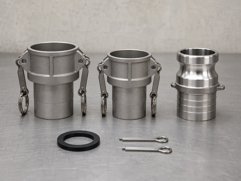
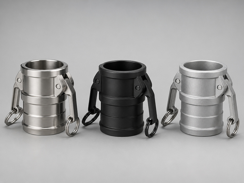
A coupler that restricts flow is the most common single culprit downstream of a healthy regulator. If a tool improved after a coupler swap but still falls short, the bore of the body may be the limit; the choice between standard and high-flow bodies is set out in our comparison of industrial pneumatic couplers. For a heavy impact wrench, a high-flow quick-connect coupler is often the difference. The matching hose is in our air hose collection.
Maintenance and Safety for Air Regulator Service
A regulator that is serviced on a schedule rarely appears in a fault table, and the same habits answer how to repair air compressor regulator units without sending them out. These rules are the ones our test bench follows:
- Relieve all pressure before servicing, then open a bowl or bonnet on a zero gauge reading.
- Lock out the compressor and isolate the branch before any work on the regulator, filter, or drain.
- Never exceed the regulator’s rated inlet pressure, because a 150 to 300 PSI body is not a 500 PSI body.
- Drain the filter bowl on a schedule rather than when it looks full, because water reaches the seat first.
- Replace the diaphragm and seals as a set, not one at a time, so the next weakest seal does not fail in a month.
- Keep a spare seal kit and a spare gauge on the shelf, because both are inexpensive and both stop a shift.
Table 7. A simple regulator and filter maintenance schedule
| Task | Interval | Why it matters |
|---|---|---|
| Drain the filter bowl | Daily in a humid shop, weekly otherwise | Water reaches the seat before it reaches the glass |
| Check the outlet gauge against a known-good gauge | Annually | A drifting gauge hides a real fault and sends the diagnosis the wrong way |
| Replace the filter element | On the maker’s interval | A loaded element becomes a flow restriction and a source of pressure drop |
| Inspect the diaphragm and seals | Every service, or on any bonnet leak | The diaphragm is the first part to fail on a relieving unit |
| Re-check the set pressure under load | After any hose, coupler, or tool change | The set point belongs to the whole system, not to one regulator |
Compressed air is stored energy, and the rules that govern it are not optional. The US Occupational Safety and Health Administration limits cleaning with compressed air to 30 PSI under 29 CFR 1910.242(b), covers tool condition under 1910.242(a), and applies a construction-specific rule at 29 CFR 1926.302(b)(5). For a regulator, the practical version is short: isolate the branch, bleed it, verify zero on the gauge, and only then open the unit.
Air Regulator Not Working FAQs
Why is my air regulator not building pressure?
Most often the adjusting screw is backed fully out, the supply pressure sits below the set point, or the spring and diaphragm have failed. Turn the screw clockwise and watch the outlet gauge; if it does not move, check the tank gauge. If the tank is above the set point and the outlet stays at zero, the diaphragm or seat has failed and the unit needs a seal kit.
Why is my air compressor regulator leaking air?
Two groups of leak dominate: those that vent through the bonnet or the adjusting screw, and those that pass the bowl or drain. A bonnet leak is usually a ruptured diaphragm or a worn stem seal. A bowl leak is usually an O-ring, a gasket, or a drain valve that was over-tightened. An air compressor regulator leaking from the bonnet on a relieving unit may simply be a short vent after a tool stops, which is normal.
My tool goes weak but the tank gauge never moves: how do I know whether the regulator or the compressor is at fault?
Compare the tank gauge with the regulator outlet gauge at rest, then again with a tool running. If the tank gauge itself falls below the set point when the tool runs, the compressor is the limit, not the regulator. If the tank holds steady while the outlet falls, the regulator or the flow path downstream is the fault.
Pressure falls only when a tool is running: what causes pressure to drop when I use a tool?
Pressure drops under load for two reasons: normal droop, and a restriction that starves the tool. Every regulator loses some outlet pressure as flow rises, so a small dip is expected. A large drop points to an undersized hose, a restrictive coupler, a loaded filter, or a compressor that cuts out too low, which is how most air compressor regulator problems actually resolve.
How do I adjust the air regulator on my compressor?
Relieve the downstream pressure, back the screw out until the gauge reads zero, then turn it in slowly and watch the outlet gauge only. Set the target with no flow, then open the tool and re-check under load. If the reading falls too far with the tool running, do not simply raise the set point; correct the supply or the bore instead. Lock the setting when it is right.
Is it worth repairing an air compressor regulator, or should I replace it?
Repair it when the fault is a seal, spring, seat, or gauge, because those parts are inexpensive and the body is the costly half. Replace it when the body is cracked, the port is cross-threaded, or the housing is a crimped plastic type that was never serviceable. Learning how to repair air compressor regulator seals and seats covers most of the faults in this article.
Why does my regulator hum or chatter?
Chatter usually comes from unstable control at low flow, a fatigued spring, or pressure pulsing from a small compressor feeding a large receiver. Open a second tool to raise flow and listen: if the noise stops, the regulator is simply controlling at the bottom of its range. Adding downstream volume often smooths it. A chattering regulator is irritating far more often than it is dangerous.
The tank is full and the outlet gauge still reads zero: why does the gauge read zero when the tank is full?
A gauge that reads zero with a full receiver is usually a failed gauge, a blocked gauge port, or a regulator that is backed fully off. Swap in a known-good gauge and open the adjusting screw. If pressure then appears, the original gauge or its port was the fault. The gauge is the cheapest part in the assembly, so replace it rather than trusting it.
What is regulator droop, and is it a fault?
Droop is the fall in outlet pressure as flow through the regulator increases. It is a normal property, not a fault, because the spring and diaphragm must move to open the valve. Regulator pressure drop becomes a fault only when it is larger than the flow curve predicts, or when pressure collapses under a light load. Compare the regulator at two flow rates before condemning it.
How to adjust air regulator pressure so it holds at the tool?
Set the target under load rather than at rest. Establish the set point with no flow, then open the tool and watch the gauge at the tool inlet. If it falls below the 90 PSI most tools are rated for, raise the set point only after checking the hose bore and the couplers. Over-setting the regulator to mask droop is what pushes a whole shop above its intended pressure.
Next Steps: Diagnose Before You Replace
Most air regulator not working calls end with one of four fixes: a seal kit, a corrected installation, a cleared flow restriction, or a supply that was too low all along. Each one is cheaper than a new regulator, and each one is found with a gauge rather than a guess.
The action list is short. Set the regulator and read the outlet gauge at rest. Open the tool and read it again under load. If the two readings disagree, work the symptom table before buying anything. Check the arrow on the body and the bowl in front of it. Then verify the hose bore and the coupler against the tool’s demand, because the search for how to repair air compressor regulator faults usually ends with a five-dollar seal rather than a new unit.
HENGHUA manufactures air hose fittings, quick connect couplers, air hoses, and hose assemblies for distributors, retailers, and OEM brands worldwide. Fittings are machined from brass, zinc-plated steel, or stainless steel, thread-checked against NPT and BSP gauges, and pressure-tested to rated working pressure before shipment. The range covers 1/4, 3/8, and 1/2 in plugs and sockets in M-, A-, and E-style interchange profiles, hose barbs, adapters, reducers, kits, spare O-rings, and regulator and filter units.
Factory-direct pricing, short lead times on bulk orders, private labeling, custom packaging, and OEM/ODM branding are all available. If you are standardizing a shop, a distribution range, or an OEM program, contact our team for a quote and samples, and we will help you match the style, size, and thread standard to your market.
About the author. This article was prepared by the HENGHUA engineering team, which designs and pressure-tests pneumatic fittings, air hoses, and regulator and filter units. The team works daily with thread gauges, flow bench measurements, and pressure-testing, and supports customers with product selection, material choice, and application questions.
 English
  Spanish
  Portuguese
  French
  German
  Arabic
  Russian
  Indonesian
  Japanese
  Korean