
The question after a hose release in a petrochemical plant is never only what broke, but why it broke here and now. Hose failure analysis answers that. The method preserves the failed item, reconstructs its service history, opens the tube for inspection, and compares what it finds against the design intent.
This guide sets out that four-step method, then builds a chemical-service taxonomy of failure modes. The branches are chemical attack and tube swelling, permeation-driven degradation, galvanic corrosion at the fitting, thermal and steam cycling, vacuum collapse in suction service, and assembly error. Each branch ends in a specification or an operating change. Mechanical causes are covered in a linked guide rather than restated here.
Design ratings cited below come from the named standards; regulation citations follow the current text of the cited section. About 13 min read.
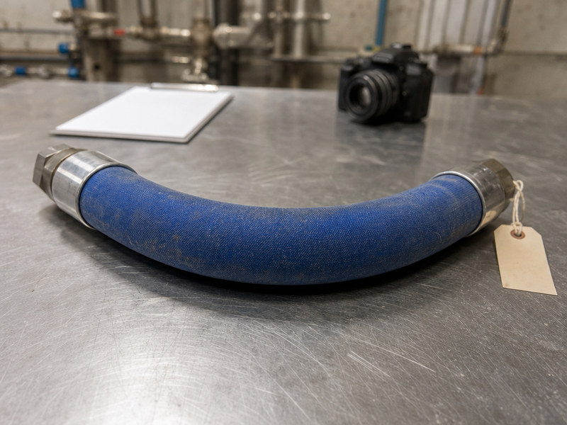
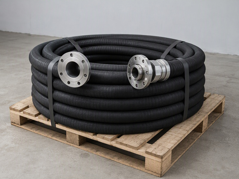
Figure 1. A failed chemical hose assembly, tagged and photographed before any cleaning or cutting.
What Hose Failure Analysis in a Petrochemical Plant Actually Involves
The scope is narrower than a plant-wide reliability review and wider than a single inspection. This analysis treats one assembly as four interacting parts: the tube that contacts the medium, the reinforcement that carries the pressure, the cover that shields the reinforcement, and the end fitting that joins the hose to the plant. A failure usually starts in one part and appears in another, so the item is documented before anyone cleans or cuts it.
Three questions organize the whole exercise:
- Where did the failure originate: tube, reinforcement, cover, or fitting?
- Which service condition drove that origin: chemistry, temperature, pressure cycling, vacuum, mechanical load, or handling?
- Was the assembly right for the duty, or right in type but wrong in execution?
The origin, the service condition and the assembly check matter because a petrochemical hose rarely fails from one dramatic event. It fails where a chemical, a temperature, a load and a small assembly error meet. A hose that is chemically correct but over-crimped at the ferrule, or thermally correct but run under vacuum, will show damage that points at the wrong cause until the history is checked.
The design intent comes from the specification and the standards it names. For chemical service the anchor is EN 12115:2021, which covers rubber and thermoplastics hose assemblies for liquid or gaseous chemicals and defines Type D and Type SD assemblies plus four grades based on electrical properties. The standard sets a service range of −20 °C to +65 °C and a working pressure up to 10 bar.
For hydrocarbon, solvent and chemical transfer in thermoplastic composite construction, EN 13765 sets five types. Bores run from 25 mm to 250 mm, working pressures from 4 bar to 14 bar, and working temperatures from −30 °C to +160 °C. Those figures are what any failed assembly is measured against during analysis.
Both windows are the classification and specification envelopes of the named standards, not a universal limit for chemical hose. A build is qualified against the standard and the liner its construction follows, and the duty temperature is checked inside that envelope. Record which envelope each figure belongs to, so the report compares like with like.
How to Run a Hose Failure Analysis: Preserve, Record, Cut, Compare
The method has four steps, and the order is not negotiable. Each step protects the evidence the next one needs. The first two steps decide what the later two can conclude.
Step 1: Preserve the Failed Item Before It Is Cleaned
Tag the assembly with a unique number and its location in the plant. Photograph it in place so the orientation, the bend radius and the state of the joint are recorded before anything moves. Do not wash it, cut it, or drag it across the floor. Residue inside the bore and staining on the cover are data.
On our test bench the most common mistake is a well-meaning technician who cleans the hose first. That single action destroys the evidence of which medium reached which layer. A preserved item can still be cut later; a cleaned item cannot be un-cleaned, and the chemical trace is gone.
Step 2: Record the Service History
Build a short history from records rather than memory. Pull the medium and its concentration, the operating temperature and any steam or cleaning cycle, the working pressure and the pump characteristics, and the dates of installation and last test. Count the transfers or pressure cycles if the site logs them.
The identification code marked on the hose, together with its pressure rating and size, ties the item to its factory test record. Age alone rarely explains a failure. Age against duty does, and duty is what the record shows.
Step 3: Cut a Section Open
Cut the assembly lengthwise through the failure and through at least one sound section for comparison. Inspect the tube bore for swelling, softening, cracking or blistering. Look at the reinforcement for corrosion, broken strands or displacement. Check the cover for blistering that suggests permeation, and cut the ferrule end to expose the fitting-to-hose interface.
Here the failure signature is read, not assumed. A swollen bore points in one direction, a corroded wire in another, a cracked cover in a third. Two cut sections, one failed and one sound, turn a description into evidence a reviewer can check.

Figure 2. A lengthwise cut exposes tube swelling and a softened bore after chemical attack.
Step 4: Compare the Section with the Design Intent
Match what the section shows against what the specification promised. The comparison is a set of questions. Was the tube compound rated for this medium at this concentration and temperature? Was the assembly worked within the pressure and temperature range of its standard? Was the end fitting matched to the hose and to the mating connection?
A failure that survives all four steps is rare. When it happens, the anomaly is usually in the operating envelope rather than the hardware. That outcome is still a result: it means the specification was correct for the design case and the plant ran outside it.
Table 1. The four steps of the root-cause method and the evidence and record each step produces
| Step | Action | Evidence produced | Record that proves it |
|---|---|---|---|
| 1. Preserve | Tag the assembly, photograph it in place, stop further handling. | Failure position, orientation, bend radius, joint state before disturbance. | Photo log |
| 2. Record | Rebuild the service history from records and the hose marking. | Medium, concentration, temperature, pressure, cycles, install and test dates. | Factory test record |
| 3. Cut | Open the failure and one sound section lengthwise. | Bore condition, reinforcement state, cover condition, ferrule interface. | Cut-section photo log |
| 4. Compare | Test the signature against the design intent. | Confirmation that the cause is chemistry, mechanics, thermal, vacuum, or assembly. | Specification and resistance chart |
A Hose Failure Analysis Taxonomy for Chemical Service
Chemical-service hose failure causes fall into six recognizable branches. The taxonomy below organizes the hose failure modes by the mechanism that drives the damage, so a visible sign can be traced back to a service condition. Use it after the cut-open step, when the physical evidence is in front of you.
Chemical Attack and Tube Swelling
The tube compound is attacked when the resistance rating does not cover the actual concentration and temperature. The result is swelling, softening, a color change, or a spongy bore. A swollen tube reduces the free bore and can grip the reinforcement, and a softened tube loses its bond to the fitting.
The remedy is always the same. Check the manufacturer’s chemical resistance chart against the specific medium, concentration and temperature. Then change the tube compound or the operating condition before replacing the hose with an identical build. Replacing like for like without that check simply resets the clock on the same failure.
Permeation-Driven Degradation
Some media pass through the tube wall molecule by molecule rather than attacking the tube polymer. The visible sign is a cover that blisters or lifts, or a persistent odor and a wet film on the outside of a hose that is not leaking. This branch is easy to misread as a mechanical cover fault.
The mechanism deserves its own treatment, and the companion article on why waiting for a chemical hose leak is costly covers permeation in depth. For this analysis the point is narrower. Record permeation as a branch, note the medium and the temperature, and treat repeated cover blistering as a reason to review the tube material.
Galvanic Corrosion at the Fitting
Where a stainless or carbon steel fitting meets a dissimilar metal, a wet environment and a conductive medium, galvanic corrosion can eat the fitting from the inside. It shows as pitting, a rust-colored stain at the ferrule, or a fitting that has lost wall thickness at the thread. A stagnant pocket where liquid sits between transfers makes it worse.
Prevention is material selection and joint design. Match the fitting metal to the medium, and avoid a low point where residual liquid collects. Left uncorrected, a chemical hose failure at the fitting will recur on the same schedule.
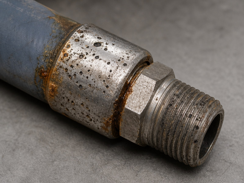
Figure 3. Pitting and staining at the ferrule are typical signs of galvanic corrosion at a fitting.
Thermal and Steam Cycling
Steam cleaning, hot product and repeated heating and cooling drive a different set of failures. The cover cracks, the tube hardens, and the bond between tube and reinforcement weakens as the layers expand and contract at different rates. A hose rated to 160 °C in continuous service may still suffer if steam at a higher temperature is used to clean it.
Check the cleaning procedure as part of the history, not only the process fluid. The saturated steam hose guide covers how steam service and its cleaning cycles differ from a liquid duty, which is where most thermal failures begin.
Vacuum Collapse in Suction Service
Applicability: any line that runs under vacuum needs a suction build. A pressure-only hose flattens under full vacuum, and the kink stays after the pump stops, so the assembly is scrap and a buckled reinforcement does not recover by straightening.
Compare a suction build with a pressure-only hose before the next purchase. The suction hose guide explains how the reinforcement differs, and why a delivery hose used on the inlet side collapses under full-vacuum conditions.
Assembly Error
Assembly error is the branch created by people, not by the medium. A ferrule crimped to the wrong diameter, a band clamp under-torqued, a fitting with the wrong thread form, or a hose cut too short and installed with a tight bend all produce failures that look like something else.
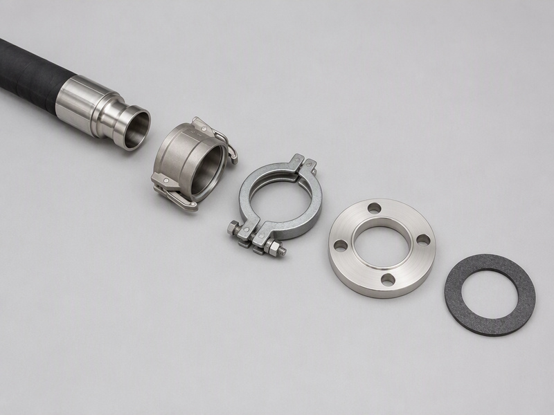
Check the end-connection method against the hose construction. The coupling selection guide sets out how crimped, swaged and reusable ends behave, and how to verify the thread and seal at the joint. Assembly error is the least expensive branch to fix, because it needs a procedure, not a new material.
Table 2. Chemical-service failure branches, visible signs, driving conditions and prevention
| Failure branch | Where it shows | Driving condition | Prevention action |
|---|---|---|---|
| Chemical attack | Swollen or spongy bore, color change | Medium, concentration, temperature above rating | Re-check resistance chart; change compound or condition |
| Permeation | Cover blistering or lifting, odor, wet film | Permeable medium at elevated temperature | Review tube material; track cover condition |
| Galvanic corrosion | Pitting, staining, thinning at ferrule or thread | Dissimilar metals, wet conductive medium | Match fitting metal to medium; drain the low point |
| Thermal cycling | Cracked cover, hardened tube, weak bond | Steam cleaning or hot product cycles | Cap cleaning temperature; specify for peak, not average |
| Vacuum collapse | Flattened or permanently kinked bore | Pump inlet duty with a pressure-only build | Inlet-side builds specified for vacuum duty |
| Assembly error | Failure at the ferrule or thread | Wrong crimp, torque, thread form or length | Fix the assembly procedure and inspection step |
How Do You Read a Failure Signature Against the Design Intent?
Once the section is open, the physical signature narrows the branch quickly. The table below pairs what you see with the mechanism most likely to produce it, and with the evidence that confirms the match. Treat it as the start of an argument, not as a verdict.
Order matters when you read the table. Always confirm chemistry before mechanics. A corroded reinforcement can be caused by a chemical that reached the wire through a permeated or cracked inner layer. In that case the corrosion is a symptom, and the tube is the root cause.
Table 3. Telling two similar-looking chemical hose failure signatures apart before the conclusion is written
| Similar pair | Points to | Rule-out check |
|---|---|---|
| Bore swollen with an intact cover | Chemical attack on an under-rated tube | Resistance chart for the actual medium, concentration and temperature |
| Clean bore with a blistered or lifted cover | Permeation through the tube wall | Cover condition on sister hoses on the same duty |
| Clean bore with damage at the ferrule only | Assembly error | Crimp diameter, clamp torque, thread form and installed bend radius |
| Pitted or thinned fitting metal | Galvanic corrosion at the end metal | Fitting and tube metals, standing liquid at a low point |
Where Do Mechanical Causes Fit in This Chemical-Service Analysis?
Most chemical-service failures are chemical. Abrasion from dragging a hose over concrete, kinking at a tight bend, and pressure surge from a fast-closing valve are the same mechanical causes that shorten the life of any industrial hose. They are set out in full in the hydraulic hose failure-cause guide, which lists the ten common problems and their prevention.
Keep this analysis chemical-service specific. When the cut section opens to a sound tube, the damage belongs to the mechanical group, and the general guide takes over from this chemical taxonomy. Those hydraulic hose failure reasons are the right reference for the mechanical hose failure causes, and keeping the two apart stops the branches being confused.
A hose burst cause is often reported as simple over-pressure. Sometimes that is correct, but the pressure limit itself has more than one definition. Confirm which number applies before writing the burst conclusion, using the comparison of working pressure versus burst pressure as the reference frame.
Hose Failure Analysis FAQs
What does a hose failure analysis involve?
A hose failure analysis is the structured method used to find why a specific hose assembly failed. It preserves the failed item, records its service history, cuts a section open, and compares the physical evidence against the design intent. The output is a root cause and a preventive action, not just a replacement hose. It applies to any industrial hose but is used most in chemical, steam and vacuum service, where a release carries extra risk.
Why do chemical hoses fail in petrochemical service?
Typical hose failure causes are conditions that exceed what the hose was specified for. Common drivers are an under-rated tube compound, a temperature above the rated range, a steam or cleaning cycle not in the original design, a suction duty on a pressure-only hose, and small assembly errors at the ferrule. Most failures combine two of those. Failures that reach the medium usually leave the end fitting intact.
What are the most common hose failure modes in chemical service?
The hose failure modes sort by where the damage sits, not by when it appeared. Read the cut section from the bore outward. A bore that has lost its profile puts chemistry first, a sound bore under a damaged cover puts permeation first, and damage confined to the end fitting points at the joint rather than the medium. Work back to the mechanism only after the position is fixed, and record the position before the section is cut further.
How do I tell chemical attack from permeation?
Look at where the damage sits in the wall. Chemical attack shows inside the bore as swelling, softening or discoloration, because the medium is degrading the tube. Permeation shows on the cover as blistering or lifting, because molecules have passed through the tube wall. A wet film and a persistent odor on an otherwise intact hose also indicate permeation. When both signs appear, treat permeation as the cause and the tube damage as its result.
A stainless fitting on a carbon steel part keeps pitting — is that galvanic corrosion?
Yes, when the conditions line up. You need two dissimilar metals in contact, an electrolyte, and a conductive medium. A stainless fitting mated to a carbon steel part, with a wet conductive liquid sitting in a low pocket, forms a small battery. Over time the less noble metal loses section. Look for pitting, staining or a fitting that feels lighter at the thread. Correcting the material pairing is the fix.
What does steam cycling do to a chemical hose?
Steam cycling leaves no single signature, so the record decides the case. If the logged cleaning temperature sits above the rated range for the construction, treat the failure as a procedure problem and correct the cleaning step before replacing the hose. If the record shows the cleaning step inside the range, read the bond line in the cut section and treat the failure as mechanical fatigue.
What happens to a delivery hose moved to the inlet side of a pump?
Suction and delivery reinforcement resists external collapse; a pressure-only build is designed for internal pressure alone. That difference decides the installation rather than the hose: check which side of the pump the assembly sits on before the next job, and specify the inlet side for vacuum whenever a pump can pull the line down.
What assembly errors cause the most failures?
Start at the joint. A joint failure points to the assembly step, so work through the crimp, the clamp, the thread form and the bend radius in that order. Then compare the failed end with a sound end from the same batch: a joint that passed at installation and failed later points to field re-termination without the same crimp control.
Should every failed hose be analyzed, or only the ones that caused a release?
Analyze every failure that caused a release, a near miss or an unplanned shutdown. For routine wear-outs, analyze the first of a repeated pattern and then sample. One failure is an incident; a repeating pattern across sister assemblies is a trend. Recording results against the assembly identification code lets a plant see a pattern before it becomes a maintenance cost problem. Regular inspection catches most problems before a release makes this analysis necessary.
Can a hose that failed at the fitting be repaired and returned to service?
Sometimes, but only when the failure is at the end and the hose body is sound. A cut-back and re-termination is possible when the remaining length is enough and the tube shows no degradation. If the bore is swollen or the reinforcement corroded, repair only hides the cause. For a chemical hose failure that reached the tube, replace the assembly and correct the specification that allowed it.
Are hydraulic hose failure reasons relevant to chemical hoses?
Yes, whenever the evidence points to mechanics rather than chemistry. Use the hydraulic hose failure reasons list when the cut section shows a clean bore and an intact tube with a frayed cover or a flattened reinforcement. Abrasion, kinking, crushing and pressure surge are mechanical signs, and they are handled outside this chemical taxonomy rather than by the six chemical branches of this taxonomy.
A hose burst below its rated pressure — what is the most common hose burst cause to rule out first?
An over-pressure event is the most frequently reported hose burst cause, but it is not the only one. A hose can also burst below its rating when the reinforcement has already been weakened by corrosion, chemical attack or a bad crimp. Check the pump and relief setting against the maximum allowable working pressure, then inspect the reinforcement in the cut section. That two-part check separates over-pressure from a weakened assembly.
Turning Hose Failure Analysis into Prevention
A completed investigation is only useful if it changes something. The table below converts each common finding into a specific change in the specification or the procedure. Keep a copy with the maintenance record so the next failure can be compared against the last decision.
Table 4. Converting a failure finding into a specification or procedure change
| Finding | Standard or rule to check | Change to make |
|---|---|---|
| Under-rated tube compound | EN 12115:2021 service range; EN 13765 Annex A inner-wall selection | Re-select the tube against the resistance chart; update the data sheet |
| Temperature above rating | EN 12115:2021 envelope to 65 °C; EN 13765 envelope to 160 °C | Cap the process or cleaning temperature, or change the construction |
| Permeation on the cover | EN ISO 4080 as a test method reference | Review tube material and wall for the medium; track cover condition |
| Fitting corrosion | Fitting metal versus medium and mating part | Change the fitting material; remove the liquid trap |
| Vacuum collapse | Suction versus delivery reinforcement | Specify a suction and delivery build for every inlet-side hose |
| Assembly fault | End-connection method and thread form | Retrain the assembly step; add a joint check to the inspection |
| Missing test record | 33 CFR 156.170 test at 1.5 × MAWP (maximum allowable working pressure) where the facility rule applies | Tie the hose marking to its test record; test on schedule |
Three habits make the whole system work. First, mark every assembly and record its test data, so the history exists when you need it. Second, treat the inspection checklist as the early-warning layer that feeds the analysis. Third, feed the findings into the lifecycle and cost plan, because a corrected specification is cheaper than a repeated maintenance and lifecycle cost cycle.
HENGHUA is a professional manufacturer of chemical hoses, chemical hose assemblies, industrial hoses and hose fittings. We supply distributors, EPC contractors and OEM brands worldwide. Constructions cover rubber, including EPDM (ethylene propylene diene monomer) and other compounds, UHMWPE (ultra-high-molecular-weight polyethylene), PTFE (polytetrafluoroethylene)-lined and thermoplastic composite builds. Assemblies are terminated with crimped, swaged or banded hose ends, flanged ends to ASME or EN patterns, and cam and groove couplings. They come in carbon steel, 304 and 316 stainless steel, aluminium, brass and PP or PVDF where the medium demands it.
Every assembly is hydrostatically tested to its rated working pressure before shipment, and marked with its maximum allowable working pressure, size and identification code. That marking is what makes a later hose failure analysis possible, because it ties the field item to a factory test record. Commercial terms include factory-direct pricing, short lead times for bulk orders, private labeling, custom packaging, OEM and ODM branding, and warranty. For the full chemical range, see the chemical hose collection.
When a hose fails, send us the medium, the concentration, the operating temperature, the working pressure and photographs of the cut section. Our engineering team will review the signature against the specification and recommend a corrected build. Request a quote and samples through our chemical hose quotation desk to start that review.
About the author. This article was prepared by the HENGHUA engineering and test team, which designs and pressure-tests chemical hose assemblies for chemical, petrochemical, marine and industrial transfer duty. The team works from factory hydrostatic test results, assembly records and field reports from distributor and contractor programs. The guidance here reflects that hands-on work rather than a single project. It is written to help plant engineers and maintenance planners run a defensible hose failure analysis and turn the result into a better specification.
 English
  Spanish
  Portuguese
  French
  German
  Arabic
  Russian
  Indonesian
  Japanese
  Korean