
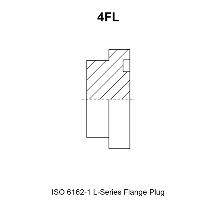
Адаптер 4FL представляет собой заглушку с фланцем серии L по стандарту ISO 6162-1 с четырьмя болтами. Он закрывает фланцевое отверстие, обработанное в соответствии со стандартом серии L (код 61) с четырёхболтовой схемой расположения, что позволяет перекрыть насос, клапанный блок, коллектор или шланговую линию, не затрагивая остальную часть соединения. У него имеется только одно соединение: фланцевая поверхность, прилегающая к отверстию.
Поверхность фланца должна точно соответствовать размерам отверстия по размеру фланца, схеме расположения болтов, диаметру патрубка и уплотнительному кольцу, поскольку герметичность соединения обеспечивается за счет эластомерного уплотнительного кольца, зажатого между поверхностью фланца и поверхностью отверстия. Такое точное соответствие является обязательным условием для исключения утечек в заглушенном отверстии.
Принцип уплотнения данной серии: заглушка уплотняется с помощью уплотнительного кольца на торце фланца. В зоне уплотнения отсутствует резьба, поэтому не требуется компенсация за сдвиг, и не используется резьбовой герметик. Четыре болта прижимают фланец к поверхности патрубка и сжимают уплотнительное кольцо в его канавке. В отличие от резьбового переходника, в этом соединении отсутствуют герметик и угол затяжки.
Основные преимущества
- Закрывает фланцевое отверстие кода 61 с помощью одной детали вместо пары фланцев, заглушки и отдельного уплотнителя.
- Уплотнение с уплотнительным кольцом, благодаря чему при затяжке болтов происходит зажим контролируемого эластомерного уплотнителя, а не за счет прессовой посадки резьбы.
- Восемь размеров фланцев серии L в одной серии — от 1/2″ до 3″.
- Головка с шестигранным фланцем, что позволяет удерживать или извлекать заглушку с помощью гаечного ключа во время технического обслуживания.
- Углеродистая сталь с цинковым покрытием с трехвалентным хромом; для применения в коррозионных средах и в морских условиях доступна нержавеющая сталь марки 304 или 316.
- Каждая партия перед упаковкой проверяется на соответствие чертежу с помощью контрольных приборов и измерений.
1. Для чего нужен адаптер 4FL
Адаптер 4FL представляет собой гидравлический переходник для четырехболтового фланцевого патрубка серии L по стандарту ISO 6162-1. Он заменяет фланцевый наконечник шланга или трубы, который обычно устанавливается на патрубок, и превращает патрубок в тупиковый.
Заглушка имеет фланцевую поверхность с канавкой для уплотнительного кольца под головкой и гладкий цилиндрический штифт. Штифт вводится в отверстие, фланцевая поверхность прилегает к поверхности отверстия, а четыре болта сжимают обе поверхности вместе. Уплотнение обеспечивает указанное для данного размера уплотнительное кольцо, поэтому нагрузка от болтов выполняет только одну задачу: удерживает поверхности вместе.
Типичными причинами для заглушки порта являются ввод в эксплуатацию коллектора с неиспользуемыми станциями, отключение ответвления на время технического обслуживания и гидравлические испытания блока с закрытым одним выходом.
Поскольку соединение осуществляется посредством фланцевой поверхности, а не резьбы, предельное рабочее давление заглушки определяется серией фланца, размером фланца, классом используемых болтов и классом давления, указанным для данного размера, а не моментом затяжки резьбы.
Данная серия относится к семейству фланцев с четырьмя болтами по стандарту ISO 6162-1, а именно к серии L, обозначаемой кодом 61. Серия S, предназначенная для более высокого давления и обозначаемая кодом 62, представляет собой отдельный стандарт — ISO 6162-2 — с иными размерами фланцев и собственной серией заглушек.
2. Технические характеристики 4FL
2.1 Соединение 1 — торцевая поверхность фланца серии L по стандарту ISO 6162-1 с четырьмя болтами
- Стандарт и серия фланцев: ISO 6162-1, серия L (код 61), фланец с четырьмя болтами.
- Доступный диапазон размеров фланцев: от 1/2″ до 3″, с шагом, указанным в таблице 2.5.
- Тип / форма: штекер мужского типа с фланцевой головкой, канавкой для уплотнительного кольца и гладким цилиндрическим стержнем, входящим в паз.
- Способ уплотнения: эластомерное уплотнительное кольцо, зажатое между торцом фланца и торцом патрубка; в зоне уплотнения отсутствует резьба.
- Стандарт соединительного патрубка: фланцевый патрубок серии L по стандарту ISO 6162-1 с четырёхболтовой схемой крепления и отверстием под патрубок, соответствующим размеру фланца.
2.2 Соединение 2 — закрытый конец (без выхода)
- Стандарт и серия фланца: отсутствуют. Второй конец представляет собой сплошную закрытую головку.
- Доступный диапазон размеров: закрытая головка представляет собой фланцевую головку, поэтому для неё действуют те же размеры фланцев от 1/2″ до 3″, что и для соединения 1.
- Тип / форма: закрытый, не является портом. Второго соединения, выхода и сквозного отверстия нет.
- Способ уплотнения: на данной стороне не применяется; корпус заглушки цельный.
- Стандарт соединительного разъема: не применимо. На этом конце имеется шестигранник, служащий для фиксации вилки.
Соединения 1 и 2 считаются зеркально расположенными блоками лишь в том смысле, что соединение 1 является уплотняющей стороной, а соединение 2 — закрывающей стороной. Адаптер 4FL имеет один соединительный конец, поэтому покупатель указывает размер фланца один раз, выбирая его из столбца «РАЗМЕР ФЛАНЦА» таблицы 2.5.
2.3 Конструкция и материалы
Корпус изготавливается из прутка на токарных станках с ЧПУ: шпиндель, торцевая поверхность фланца, канавка для уплотнительного кольца и шестигранная головка обрабатываются за одну установку, благодаря чему шпиндель остается соочным с торцевой поверхностью фланца и отверстиями под болты.
- Материал корпуса: в стандартной комплектации — углеродистая сталь; по запросу — нержавеющая сталь марки 304 или 316; для отдельных типоразмеров — латунь.
- Покрытие и отделка: в стандартной комплектации — цинковое покрытие с трехвалентным хромом (Cr³⁺) для углеродистой стали; возможно нанесение цинк-никелевого покрытия. Толщина покрытия и коррозионная стойкость подтверждаются для каждого заказа индивидуально, а не указываются в качестве типовых значений.
- Варианты материалов уплотнительных колец: NBR, FKM (типа Viton) и EPDM, подбираемые с учетом характеристик рабочей среды и температуры в порте.
- Технология обработки: токарная обработка прутка, формирование торцевой поверхности фланца и канавки для уплотнительного кольца, а также проверка соответствия чертежу.
- Особенности головки: шестигранная фланцевая головка, позволяющая затягивать заглушку с помощью гаечного ключа, а также канавка для уплотнительного кольца под фланцем и гладкий штифт. В данной серии отсутствуют переборки.
2.4 Давление и температура
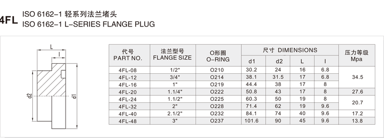
В отличие от резьбового переходника, для переходника 4FL в каталоге указан класс давления для каждого размера фланца. Значения, указанные в исходной таблице, составляют 34,5 МПа для моделей 4FL-08–4FL-16, 27,6 МПа для моделей 4FL-20 и 4FL-24, 20,7 МПа для 4FL-32, 17,2 МПа для 4FL-40 и 13,8 МПа для 4FL-48. Это значения, указанные для фланцев серии L, и они уменьшаются по мере увеличения размера фланца.
Класс давления — не единственный фактор. Давление, которое может выдержать заглушенный патрубок, также зависит от марки и длины болтов, состояния торцевой поверхности патрубка, материала уплотнительного кольца, температуры рабочей среды и материала корпуса. В случае эксплуатации при давлении, превышающем указанный класс, для корпусов из нержавеющей стали или при использовании специальных комбинаций рабочее давление подтверждается инженерным отделом компании HENGHUA для каждого заказа отдельно с учётом размера фланца, марки болтов, способа уплотнения и выбранного материала.
Температура является существенным фактором и указывается здесь в качестве существенного факта. Для уплотнительных колец из NBR рабочий диапазон составляет примерно от -30 °C до +100 °C. Для уплотнительных колец из FKM (типа Viton) он составляет примерно от -20 °C до +200 °C. Для уплотнительных колец из EPDM он составляет примерно от -40 °C до +120 °C. Выбирайте состав резины с учётом рабочей среды и рабочей температуры.
Углеродистая сталь с цинковым покрытием подходит для общего применения в гидравлических системах; для коррозионных сред или морских условий следует указывать нержавеющую сталь марки 304 или 316.
2.5 Таблица артикулов и размеров
В приведенной ниже таблице представлен полный диапазон размеров изделий серии 4FL. Все размеры указаны в миллиметрах; класс давления — в мегапаскалях.
| АРТИКУЛ. | РАЗМЕР ФЛАНЦА | Уплотнительное кольцо | d1 | d2 | L | l | Мпа |
|---|---|---|---|---|---|---|---|
| 4FL-08 | 1/2″ | O210 | 30.2 | 24 | 16 | 6.8 | 34.5 |
| 4FL-12 | 3/4″ | O214 | 38.1 | 31.5 | 17 | 6.8 | – |
| 4FL-16 | 1″ | O219 | 44.4 | 38 | 17 | 8 | – |
| 4FL-20 | 1.1/4″ | O222 | 50.8 | 43 | 17 | 8 | 27.6 |
| 4FL-24 | 1.1/2″ | O225 | 60.3 | 50 | 19 | 8 | – |
| 4FL-32 | 2″ | O228 | 71.4 | 62 | 19 | 9.6 | 20.7 |
| 4FL-40 | 2.1/2″ | O232 | 84.1 | 74 | 40 | 9.6 | 17.2 |
| 4FL-48 | 3″ | O237 | 101.6 | 90 | 45 | 9.6 | 13.8 |
What each column means
- АРТИКУЛ. – the HENGHUA part number. The prefix
4FLmeans a four-bolt flange plug in the ISO 6162-1 L series, followed by the flange size code. - РАЗМЕР ФЛАНЦА – the nominal flange size of the port the plug closes, from 1/2″ to 3″.
- Уплотнительное кольцо – the O-ring designation listed for that flange size. Order the O-ring with the plug, and state the compound required.
- d1 – the first diameter marked on the series drawing, in millimetres, printed from 30.2 mm at 4FL-08 to 101.6 mm at 4FL-48.
- d2 – the second diameter marked on the series drawing, in millimetres, printed from 24 mm at 4FL-08 to 90 mm at 4FL-48.
- L – the overall length of the plug from the flange face to the top of the head, in millimetres.
- l – the flange thickness of the head, in millimetres.
- Мпа – the pressure class printed for that flange size in megapascals. In the printed catalogue the column uses merged cells: one value covers a group of rows, and the continuation rows are left blank, here shown as a dash. Where a cell carries a dash, the value printed in the same merged group applies.
Note on the two diameters: the drawing shows a spigot diameter and a flange head diameter, and the printed d1 and d2 values must be read with the drawing. The d1 values follow the published L-series flange size steps from 1/2″ to 3″. Before ordering, confirm the spigot diameter and the flange face diameter against your port drawing; HENGHUA engineering verifies the pair for your flange size on request.
Flange size and size code chart
| Size code | Flange size | O-ring listed |
|---|---|---|
| 08 | 1/2″ | O210 |
| 12 | 3/4″ | O214 |
| 16 | 1″ | O219 |
| 20 | 1.1/4″ | O222 |
| 24 | 1.1/2″ | O225 |
| 32 | 2″ | O228 |
| 40 | 2.1/2″ | O232 |
| 48 | 3″ | O237 |
The O-ring is a service item. Replace it whenever the plug is removed and refitted, and never fit a dry or stretched O-ring that has been stored loose.
3. How to Read a 4FL Part Number
A 4FL part number has two elements: the series prefix and the flange size code. This series does not use the sealing or geometry suffixes seen on other families, such as -SP, -WD, -PK, -04 or -9, because the plug has one flange connection and one closed end.
The prefix 4FL identifies the family: a plug with an ISO 6162-1 L-series four-bolt flange face. A different prefix in the same catalogue identifies a different geometry, such as the S-series flange plug, a threaded plug for an NPT or JIC connection, or an elbow or tee version of another family.
The size code is the flange size code. Worked example: 4FL-24.
4FL– flange plug, ISO 6162-1 L series, code 61.24– the 1.1/2″ flange size.- From the table: the O-ring is O225, d1 is 60.3 mm, d2 is 50 mm, L is 19 mm, l is 8 mm and the printed pressure class is 20.7 MPa.
A buyer ordering 4FL-24 therefore receives a plug for a 1.1/2″ code 61 flange port, and must supply four bolts of the correct grade and length for that port, plus the O225 O-ring in the required compound.
Check the abbreviation carefully: L series and S series both use a flange plug, but they are different standard series with different flange dimensions and different pressure classes, and the two do not interchange.
4. Installation and Fitment
A flange joint is assembled dry and clamped, not turned. HENGHUA does not print a single bolt torque figure for the series, because the correct torque depends on the bolt grade, the bolt size and the port material. Tighten to the bolt supplier’s recommendation for the grade and size used, or confirm the figure with HENGHUA engineering per order. Bring the four bolts up evenly by hand first, then tighten in stages, alternating across the flange, so the face stays square to the port.
O-ring handling: fit the correct O-ring for the flange size, in the compound selected for the fluid and temperature. Check the O-ring for cuts, flat spots and hardening before fitting, seat it in the groove without twisting it, and keep it clean and free of grit. Never reuse an O-ring that has seen service, and never fit two O-rings in one groove to make up a gap.
Face condition: both faces must be flat and clean. A burr, a paint run or a raised scratch prevents the O-ring from compressing evenly, and the joint will weep at first pressure no matter how hard the bolts are tightened.
No thread sealant: there is no thread in this joint. Do not apply thread tape, thread sealant or gasket compound to the flange face. Light oil on the spigot is enough to allow it to enter the port without scuffing.
Contamination control: cap the plug and the port whenever the joint is open, and keep the O-ring in its packaging until the moment of fitting. Debris that lands in the groove cuts the O-ring on first clamping.
Alignment and reuse: bring the plug squarely into the port before fitting any bolt, and check that the spigot enters without force. The body and the bolt holes can be reused if the flange face is undamaged and the head is not deformed; the O-ring is always a new part.
Common fitment errors and their symptoms:
- Fitting an S-series plug into an L-series port, or the reverse. Symptom: the bolt holes or the spigot do not line up, and the plug sits proud of the port face.
- Missing or incorrect O-ring. Symptom: a steady weep around the flange face as soon as the port is pressurised.
- Tightening one bolt fully before the others. Symptom: the flange cocks, the O-ring is pinched on one side and the joint seeps from a single point.
- Reusing a hardened O-ring. Symptom: a leak that appears only when the circuit is cold, or that returns days after assembly.
- Paint, swarf or a raised scratch on the port face. Symptom: an intermittent weep that cannot be cured by further tightening.
Six-step assembly
- Confirm the part number and flange size against the port, and check that the port is an ISO 6162-1 L-series pattern.
- Clean the port face, the spigot and the O-ring groove, and inspect the face for burrs and damage.
- Fit a new O-ring of the correct size and compound, seated squarely in the groove.
- Bring the plug squarely into the port and check the spigot enters freely.
- Fit the four bolts by hand, then tighten them in stages, alternating across the flange.
- Pressurise the circuit, check the flange face for weeping, and re-check the bolt load after the first thermal cycle.
5. Applications and Industries
Application tags for this series: hydraulic systems, water jetting, oil and gas, industrial equipment, construction machinery, agriculture, marine, material handling.
Commissioning and isolation of manifold ports. A manifold ordered with more stations than the first build needs is commissioned with the spare ports blanked. Hydraulic plug adapters close each unused station, keep the port protected from contamination and allow the station to be opened later without changing the manifold.
Repair and replacement work. When a flanged hose or tube end has to come off a machine for repair, the port can be closed with a 4FL adapter so the rest of the circuit stays in service. This keeps the oil in the system and keeps dirt out of the open port.
Pressure and leakage testing. Test benches use flange plugs to close the outlets of a block that is being pressurised. Because the joint seals on an O-ring at a clamped face rather than on a thread, the same plug can be removed and refitted repeatedly, with a new O-ring each time.
Transport and storage protection. Equipment shipped with open flange ports is protected with hydraulic plug adapters so that the face and the spigot bore are not damaged in transit.
6. Replacement and Cross-Reference Guide
Cross-reference for this series is organised by standard and sealing method, never by brand. Two hydraulic adapters interchange only if the standard series, the flange size, the bolt pattern and the sealing method all match.
The 4FL series is an ISO 6162-1 L-series, code 61, flange plug with an O-ring face seal. It is not interchangeable with an ISO 6162-2 S-series, code 62, plug, even at the same nominal size, because the flange dimensions, the bolt pattern and the pressure class differ between the two standards. It is also not a threaded part: nothing in this series seals on a thread, so a threaded plug and a flange plug are never substitutes for one another.
To identify the correct replacement, measure three things.
- Flange size and bolt pattern. Measure the bolt hole centre spacing and the bolt hole diameter, and count the holes. Compare the pattern with the L-series dimensions for the flange size. If the spacing matches code 62 instead of code 61, the port is S series and this plug will not fit.
- Spigot and O-ring. Measure the spigot diameter and the O-ring groove, and identify the O-ring by its inside diameter and cross section. A plug with the correct bolt pattern but the wrong spigot or O-ring will bolt up and still leak.
- Sealing method. Confirm that the port seals on an O-ring at a clamped flange face, which is what makes this a flange adapter rather than a thread adapter. If the port in front of you is threaded, or relies on a metal cone, the part you need belongs to a different family.
Record the three measurements with the part number, and HENGHUA can match the replacement to the series and size code from the printed table in section 2.5.
7. Ordering, Packaging and Delivery
To order the 4FL adapter, give the following information:
- Series code:
4FL. - Full part number, for example 4FL-24, taken from table 2.5.
- Flange size and the standard series it must match, in this case ISO 6162-1 L series (code 61).
- O-ring requirement, including the compound: NBR, FKM or EPDM.
- Body material and plating: carbon steel with trivalent chromium zinc plating, zinc-nickel plating, or 304 or 316 stainless steel.
- Bolt grade and bolt length, if HENGHUA is also to supply the fasteners.
- Quantity, destination and packing format.
Packaging formats: bulk cartons for line-side consumption, small boxes for distributor shelves, and labelled bags for service kits. Labelling carries the part number, the flange size, the O-ring designation and the quantity. O-rings are packed separately from the plugs unless a kitted assembly is requested.
Sample orders: validation samples and first-article parts are available for OEM programmes, including drawing-based manufacture of specials where the printed table does not cover the required combination.
Lead time is confirmed per order, because it depends on the flange size, the material, the plating and the quantity. Send the requirement with the quantity and the required date, and HENGHUA confirms the schedule with the quotation. As a hydraulic adapter manufacturer and hydraulic adapter supplier, HENGHUA can quote the flange adapter, the O-ring and the fasteners as one kit.
8. FAQ
What is the difference between JIC 37° flare and ORFS, and which should I use?
A JIC 37° flare joint seals metal-to-metal on a 37° conical flare face under SAE J514. An ORFS joint seals a flat face against an elastomeric O-ring under SAE J1453. Neither is a flange joint. A four-bolt flange joint, which is what the 4FL series uses, seals with an O-ring in a flange groove under ISO 6162. Choose the family that matches the port already on the equipment.
Can NPT and BSPT be interchanged?
No. NPT is a 60° taper pipe thread under ANSI/ASME B1.20.1 and BSPT is a 55° taper pipe thread under ISO 7-1, so the thread form, angle and pitch differ and the two will not seal. This question does not apply to the 4FL series, because a flange plug has no thread at all. It matters when a threaded port has to be blanked, in which case order the correct threaded plug series instead.
How do I identify the correct 4FL size?
Measure the bolt hole centre spacing and the bolt hole diameter of the port, then match that pattern and the nominal flange size to the FLANGE SIZE column of table 2.5. Confirm at the same time that the pattern is code 61 and not code 62. When the flange size and the standard series both match a printed row, that row is the correct part number.
Which O-ring and material should I select?
Take the O-ring designation from the O-RING column of table 2.5 for the flange size, then choose the compound for the fluid and temperature: NBR for general mineral hydraulic oil in the range of approximately -30°C to +100°C, FKM (Viton-type) for higher temperatures up to approximately +200°C, and EPDM for water and water-based fluids in the range of approximately -40°C to +120°C. Fit a new O-ring each time the plug is refitted.
How is the working pressure of this plug determined?
The catalogue prints a pressure class for each flange size in this series, from 34.5 MPa at the small sizes down to 13.8 MPa at 3″, and that printed class is the starting point. The pressure the joint can hold in service also depends on the bolt grade and bolt length, the port face condition, the O-ring compound, the fluid temperature and the body material. For stainless steel bodies, special combinations or duty above the printed class, working pressure is confirmed per order by HENGHUA engineering, based on the flange size, bolt grade, sealing method and material selected.
What is the minimum order quantity and can I get samples?
Minimum order quantity depends on the flange size, the material and the plating, so it is confirmed with the quotation rather than published as one series figure. Samples and validation parts are available for OEM and distributor evaluation, including specials made to a drawing.
Does the 4FL adapter come with the O-ring and the bolts?
The 4FL adapter is quoted as a body, and the O-ring and the four bolts are separate items. Confirm the O-ring compound and, if required, the bolt grade and length when ordering, and state whether a kitted assembly is wanted. Stating all three when ordering a flange adapter keeps one size code matched to one port.
Can I use a code 62 plug in a code 61 port?
No. ISO 6162-1 L series (code 61) and ISO 6162-2 S series (code 62) are different flange standards with different flange dimensions, bolt patterns and pressure classes. Even where a size looks close, the faces and holes will not line up correctly, and forcing a fit loads the O-ring unevenly. Match the series first, then the flange size.
Send your requirement to HENGHUA
Send the part number, the flange size and standard series, the O-ring compound, the material and plating, and the quantity. HENGHUA confirms the match to the printed table, the seal options and the delivery schedule, and quotes the 4FL adapter that closes your port.
Related series in the same family: the 4FS adapter (flange) and the 4J adapter (plug). Browse the full Hydraulic Adapters range for the complete SAE J514 JIC, NPT, ORFS and ISO 6162 flange families.


 English
 Spanish
 Portuguese
 French
 German
 Arabic
 Russian
 Indonesian
 Japanese
 Korean