


Why This Adjustable Stud End Elbow Adapter Passes the Compliance Gate
An adjustable stud end elbow adapter is only as good as its O-ring groove and the flatness of the port face it clamps against. A groove that is 0.05 mm too deep will pass a shop air test and fail after 500 thermal cycles. Every 1CO9-OG / 1DO9-OG body we ship is produced on a dedicated stud-end machining cell, the O-ring groove is measured on a profile projector, the 7/16″-20 to 1-7/8″-12 UN threads are gauged with class 2A go / no-go rings, and the locknut is torque-tested against a reference port block. The inspection record, the O-ring batch and the heat number travel with the order.
The family is the O-ring branch of our metric elbow range: one forged body, a metric male end with a 24° cone on one leg, and an adjustable UN / UNF stud end with O-ring sealing per ISO 11926-1 (SAE J1926-1) on the other — supplied with its locknut. “C” (1CO9-OG) is the L series metric end, “D” (1DO9-OG) is the S series metric end, so the same UN port can be fed by either a light or a heavy wall tube.
Core Advantages
- Adjust, then lock. The elbow can be rotated to any clock position before the locknut is tightened, then locked in place — critical when an elbow has to feed a rigid tube run that cannot move.
- O-ring sealing instead of a metal cone. Lower assembly torque means less manifold distortion and no reliance on a metal-to-metal seat to stop the leak.
- No thread sealant. The straight UN thread does not seal on the thread; sealing is done by the O-ring at the base of the stud. Nothing to contaminate the circuit.
- Re-orientation without breaking the seal. Because the orientation is set by the locknut, the elbow angle can be corrected without disturbing the O-ring contact.
- Metric end choice. L series for standard pressure, S series when the tube run needs a heavier wall and a bigger thread.
Technical Specifications
What Is an Adjustable Stud End Elbow Adapter?
It is a 90° elbow that converts a straight-thread UN / UNF O-ring port (ISO 11926-1 / SAE J1926-1, also written ORB or ORFS-adjacent port) to a metric 24° cone tube connection, while allowing the elbow body to be rotated to any angle before it is locked. The stud end carries an O-ring that seats on the chamfer of the port, and a locknut (the “back nut”) that clamps the body shoulder against the port face and holds the chosen orientation.
Connection 1 — Metric Male 24° Cone (L or S Series)
The tube-side leg is a metric male end with an external 24° cone seat per DIN 2353 / ISO 8434-1. In 1CO9-OG the thread follows the L (light) series — M12×1.5 for 6 mm tube, M22×1.5 for 15 mm and so on. In 1DO9-OG the same tube sizes use the S (heavy) series thread, one size larger — M14×1.5 for 6 mm tube, M24×1.5 for 16 mm. The two series are not interchangeable at the port; match the thread to the port, not to the tube.
Connection 2 — UN / UNF Adjustable Stud End with O-Ring, ISO 11926-1
The imperial leg is a straight UN / UNF threaded stud end with an O-ring groove at the base, dimensioned to ISO 11926-1 (SAE J1926-1). Sizes run from 7/16″-20 (dash 04) to 1-7/8″-12 (dash 24). The port is a plain straight-thread port with a flat face and a chamfer; it is not a tapered pipe thread. Forcing this stud into an NPT, BSPT or 60° cone port will damage the port and cannot seal.
The three common interfaces that look similar but never interchange are the 24° cone (metric, DIN 2353), the 60° cone (BSP, DIN 3861 / ISO 1179) and the 37° flare (JIC, ISO 8434-2). A fourth, the straight-thread O-ring stud, uses no cone at all. Check the port drawing before ordering.
Dimensional Data
In the drawing, E is the metric end thread, F the UN / UNF stud thread, D1 the tube outside diameter, l1 the usable stud length to the O-ring face, L1 the overall length of the stud leg to the centreline and L2 the height of the metric leg — one horizontal dimension, one vertical dimension. For an elbow these two dimensions are measured along two perpendicular axes and are not symmetric: rotating the body for clearance under a valve bank changes the vertical stack height, so confirm both the L and the H direction before ordering.
S1, S2 and S3 are the across-flats hex dimensions of the three wrenching points: the metric end, the body and the locknut.
Full Dimension Table (Part Number Matrix)
Values as published in the HENGHUA catalogue drawing. Dimensions in millimetres.
| PART NO. | E — metric thread | F — UN/UNF thread | D1 | l1 | L1 | L2 | S1 | S2 | S3 | Pressure MPa |
|---|---|---|---|---|---|---|---|---|---|---|
| 1CO9-12-04OG | M12×1.5 | 7/16″×20 | 6 | 13 | 28 | 27.2 | 11 | 14 | 17 | 31.5 — L series |
| 1CO9-14-06OG | M14×1.5 | 9/16″×18 | 8 | 15.5 | 30.5 | 31.8 | 14 | 17 | 19 | 31.5 — L series |
| 1CO9-16-06OG | M14×1.5 | 9/16″×18 | 10 | 17.5 | 32.5 | 33.3 | 16 | 19 | 19 | 31.5 — L series |
| 1CO9-18-08OG | M18×1.5 | 3/4″×16 | 12 | 19 | 34 | 37.5 | 19 | 22 | 24 | 31.5 — L series |
| 1CO9-22-10OG | M22×1.5 | 7/8″×14 | 15 | 22 | 37 | 44 | 22 | 27 | 27 | 31.5 — L series |
| 1CO9-22-08OG | M22×1.5 | 3/4″×16 | 15 | 22 | 37 | 39.5 | 22 | 27 | 24 | 31.5 — L series |
| 1CO9-26-12OG | M26×1.5 | 1.1/16″×12 | 18 | 25.5 | 42 | 51 | 27 | 32 | 32 | 31.5 — L series |
| 1CO9-30-12OG | M30×2 | 1.1/16″×12 | 22 | 29.3 | 45.8 | 53.5 | 30 | 36 | 32 | 31.5 — L series |
| 1CO9-36-12OG | M36×2 | 1.1/16″×12 | 28 | 33.5 | 47.8 | 57.5 | 36 | 41 | 41 | 16 — L series |
| 1CO9-36-16OG | M36×2 | 1.5/16″×12 | 28 | 33.3 | 49.8 | 57.5 | 36 | 41 | 41 | 16 — L series |
| 1CO9-45-20OG | M45×2 | 1.5/8″×12 | 35 | 39.2 | 60.7 | 63 | 48 | 50 | 50 | 16 — L series |
| 1CO9-52-24OG | M52×2 | 1.7/8″×12 | 42 | 44.8 | 67.8 | 70.5 | 55 | 60 | 55 | 16 — L series |
| 1DO9-14-04OG | M14×1.5 | 7/16″×20 | 6 | 17.5 | 32.5 | 30 | 14 | 17 | 17 | 63 — S series |
| 1DO9-16-06OG | M16×1.5 | 9/16″×18 | 8 | 18.7 | 33.7 | 33.3 | 16 | 19 | 19 | 63 — S series |
| 1DO9-18-06OG | M18×1.5 | 9/16″×18 | 10 | 19.5 | 36 | 33.5 | 19 | 22 | 19 | 63 — S series |
| 1DO9-18-08OG | M18×1.5 | 3/4″×16 | 12 | 19.5 | 36 | 37.5 | 19 | 22 | 24 | 63 — S series |
| 1DO9-20-08OG | M20×1.5 | 3/4″×16 | 12 | 19.5 | 36 | 37.5 | 19 | 24 | 24 | 63 — S series |
| 1DO9-22-10OG | M22×1.5 | 7/8″×14 | 14 | 23 | 41 | 44 | 22 | 27 | 27 | 63 — S series |
| 1DO9-24-10OG | M24×1.5 | 7/8″×14 | 16 | 24 | 42.5 | 46.5 | 24 | 30 | 27 | 63 — S series |
| 1DO9-30-12OG | M30×2 | 1.1/16″×12 | 20 | 28.3 | 49.8 | 53.5 | 30 | 36 | 32 | 40 — S series |
| 1DO9-36-16OG | M36×2 | 1.5/16″×12 | 25 | 32.8 | 56.8 | 57.5 | 36 | 46 | 41 | 40 — S series |
| 1DO9-42-20OG | M42×2 | 1.5/8″×12 | 30 | 36.2 | 62.7 | 59.5 | 41 | 50 | 50 | 40 — S series |
| 1DO9-52-24OG | M52×2 | 1.7/8″×12 | 38 | 45.8 | 76.8 | 70.5 | 55 | 60 | 55 | 31.5 — S series |
Thread Size and Dash Chart
| Stud size | UN / UNF thread | Typical tube OD | Metric end (L, 1CO9-OG) | Metric end (S, 1DO9-OG) |
|---|---|---|---|---|
| 04 | 7/16″-20 | 6 mm | M12×1.5 | M14×1.5 |
| 06 | 9/16″-18 | 8–10 mm | M14×1.5 | M16×1.5 / M18×1.5 |
| 08 | 3/4″-16 | 12 mm | M18×1.5 | M18×1.5 / M20×1.5 |
| 10 | 7/8″-14 | 14–16 mm | M22×1.5 | M22×1.5 / M24×1.5 |
| 12 | 1.1/16″-12 | 18–22 mm | M26×1.5 / M30×2 | M30×2 |
| 16 | 1.5/16″-12 | 25–28 mm | M36×2 | M36×2 |
| 20 | 1.5/8″-12 | 30–35 mm | M45×2 | M42×2 |
| 24 | 1.7/8″-12 | 38–42 mm | M52×2 | M52×2 |
The dash number is the ISO 11926 / SAE port size, not the tube size. Two adjacent tube sizes can share one dash number, which is why the same stud appears twice in the table with different metric ends.
Material and Heat Treatment
Bodies and locknuts are carbon steel, forged or machined from bar, hardened according to pressure class and finished in trivalent chromium or zinc-nickel. Stainless 304 / 316L is available to order. O-rings are standard NBR 90 Shore A; FKM is supplied for high-temperature or aggressive fluid duty.
Working Pressure and Operating Envelope
The pressure column is the working pressure for the L or S series metric end. The UN / UNF stud end is rated to the port standard; in practice the lower of the two governs, and the tube wall sets a third limit. A 4:1 burst ratio is typical for the body.
Temperature Range
NBR O-rings: −40 °C to +120 °C. FKM O-rings: −20 °C to +200 °C. Because the seal is an elastomer, the O-ring material — not the steel — usually sets the high-temperature limit of the joint.
How to Read the Part Number Matrix
1CO9-12-04OG reads left to right: family 1CO9-OG (metric male 24° cone, L series, O-ring stud end, elbow), metric size 12 (tube 6 mm / M12×1.5), port dash 04 (7/16″-20 UNF), OG = O-ring groove. In the D series the same information appears as 1DO9-14-04OG: metric size 14 is the S series equivalent of tube 6 mm. When cross-referencing, always quote the port dash number and the metric thread.
Selection and Ordering
Selection Checklist / Decision Table
| Requirement | Choose |
|---|---|
| Standard pressure, tube 6–22 mm | 1CO9-OG (L series) |
| 63 MPa duty, tube 6–16 mm | 1DO9-OG (S series) |
| Elbow must feed a fixed tube run at a set angle | Adjustable stud end (this family) |
| Port is tapered NPT / BSPT | Use the BSPT / NPT family instead |
| Port is a metric O-ring port (ISO 6149) | Use the 1CH/1DH family |
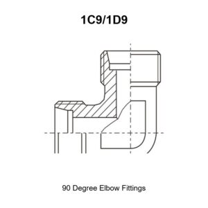
| Port face is damaged or is a 24° cone | Use the 1C9/1D9 family |
Cross Reference Service
Give us the OEM number, the port dash size and the tube OD, or send a photograph of the port. We map the part number, confirm the O-ring size and return the drawing.
Packaging and Logistics
Each elbow ships with its locknut and O-ring fitted. Cartons are marked with the part number, heat number and O-ring batch; certificates are referenced to the same lot.
Installation and Fitment Guide
Step-by-Step Assembly — Adjust, Then Lock
- Verify the port. Straight-thread O-ring port per ISO 11926-1 / SAE J1926-1. Reject any port with a tapered thread or a damaged chamfer.
- Fit the O-ring. New O-ring on the stud groove, lightly coated with the system fluid or a compatible lubricant. Never stretch or twist it into place.
- Start by hand. Screw the stud into the port until the O-ring touches the chamfer. Do not use the locknut to pull the body in, and do not grip the body hex yet.
- Set the angle. Rotate the elbow to the required clock position with the locknut loose. Full 360° freedom is available at this stage.
- Adjust, then lock. Hold the body at the chosen orientation with a wrench on the body hex and tighten the locknut against the port face to the specified torque. This compresses the O-ring and freezes the angle.
- Torque the metric end. Tighten the tube nut or the mating 24° cone connection to its own torque figure — a separate joint with a separate value.
- Verify. Check the orientation, the torque witness marks and the absence of weeping after the first pressurisation and the first thermal cycle.
Torque and Sealing Notes
Locknut torque and stud-end torque are different numbers and must not be swapped. The locknut needs enough torque to compress the O-ring and resist vibration, but not so much that it extruded the O-ring or yields the threads. The metric 24° cone end follows the standard cone-seat torque table for its thread size. Because the stud end seals on the O-ring, no PTFE tape, no thread compound and no sealant of any kind is used on the UN thread — sealant here is a contaminant, not a fix.
Installation Warnings
- Never use the locknut to install the stud; it will shear or gall the thread.
- Do not reuse an O-ring that has been through a thermal cycle or was removed from the groove.
- Do not mix 24°, 60° and 37° cone components; they will not seal against each other.
- Do not hold the metric leg to tighten the locknut; brace the body.
- Reconfirm the orientation before final torque — once the locknut is tight, the angle is fixed.
Applications and Industries
Adjustable stud end elbows are common on mobile equipment manifolds, excavator and loader valve banks, injection-moulding machines, hydraulic power units, marine deck machinery, wind-turbine pitch systems and test benches — anywhere a port must feed a rigid or pre-formed tube run at a fixed angle. The 90° adjustable stud end elbow adapter is the standard answer when the tube cannot be re-routed to match the port’s tightening position.
OEM Customization and Quality Traceability
Custom leg lengths, special O-ring compounds, alternative hex, stainless bodies and customer-specific locknuts are all available to drawing. Incoming material verification, first-article inspection, in-process thread and groove gauging, proof pressure testing on sample lots and final inspection are recorded against the order, with EN 10204 3.1 certificates on request.
FAQ
Can I change the elbow angle after tightening? Yes, provided you release the locknut first, rotate the body and re-torque the locknut. That is the purpose of the design; a fixed 24° cone stud cannot do this.
Is the adjustable stud end elbow adapter leak-free without sealant? Yes. Sealing is by the O-ring against the port chamfer. Sealant on the thread does nothing useful and can enter the circuit.
Does it fit an NPT or BSPT port? No. Those are tapered threads that seal on the thread. This part is for straight-thread O-ring ports.
Which O-ring do I need? The one matched to your port dash size per ISO 11926-1 — for example dash 04 uses the 7/16″-20 groove. We supply the correct O-ring with every elbow.
1CO9-OG or 1DO9-OG? Both have the same UN / UNF stud end. The difference is the metric end: L series (1CO9) or S series (1DO9). Choose by the tube side.
What is the difference from a 60° cone fitting? Different seat geometry and different port standard. A 60° cone seals on the cone face; this family seals on an O-ring.
Request a Quote
Send the part number, port dash size, metric thread, O-ring material, quantity and application pressure. We will confirm the O-ring size, the locknut torque and the lead time, and quote with the inspection documentation included.
Related products in this range: straight UN/UNF stud ends with O-ring sealing ISO 11926 1CO/1DO · metric thread stud ends ISO 6149 1CH/1DH · 90° elbow fittings adapter 1C9/1D9 · 90° elbow BSPT male adapter 1CT9-SP/1DT9-SP · equal tees AC/AD.
Browse the full Hydraulic Adapters range for the complete family, or contact us to request a quote, mill test reports, and samples.

 English
  Spanish
  Portuguese
  French
  German