
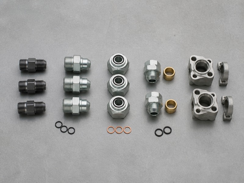
Which hydraulic fittings should you know? Thirteen — and this list of hydraulic fittings covers almost every connection on a modern machine. They are grouped here by the seal that does the work rather than by the shape of the nut. The five you will meet most often are NPT (National Pipe Taper) tapered pipe thread, its dryseal variant NPTF, JIC 37° flare, SAE ORB (O-ring boss), ORFS, and the metric 24° cone. Those five account for most mobile and industrial circuits worldwide.
Three facts decide which fitting you are holding. A thread that seals on its own flanks needs no extra part, while a straight thread always needs a distinct seal — an O-ring, a flare cone, or a bonded washer. A dash size is nominal, so a -8 in one family is not a -8 in another. And a fitting rated for the pressure is still a leak if the mating half is a different standard, which is why BSP and NPT threads of the same nominal size thread together and still weep.
The sections below answer four questions in order. Which 13 fittings matter, and what each one seals on. How they differ in thread, size, and pressure class. How to size an unknown fitting in five measurements. And which fittings appear on published lists but behave nothing like a hydraulic pressure connection. A comparison chart near the end puts the list of hydraulic fittings in one view for reference.
Which 13 Fittings Belong on a Complete List of Hydraulic Fittings?
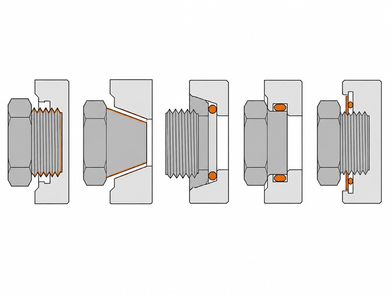
Thirteen fittings cover the practical range, and they divide into five sealing principles. Thread-flank sealing uses the threads themselves. Flared metal-to-metal sealing uses a cone. Elastomer face sealing uses an O-ring against a flat face or a boss. Captive-seal port sealing uses a bonded washer on a machined face. Flange sealing uses an O-ring held by four bolts. Once you know which principle a fitting uses, the rest of its behaviour follows.
| # | Fitting | Standard | Thread | What seals it | Typical pressure class |
|---|---|---|---|---|---|
| 1 | NPT / NPTF pipe thread | ASME B1.20.1; B1.20.3 (NPTF) | Tapered 60° | Thread flank, plus sealant on NPT | Low to medium duty |
| 2 | JIC 37° flare | SAE J514 | Straight UNF | 37° metal cone | Medium to high duty |
| 3 | SAE ORB (O-ring boss) | SAE J1926-1; ISO 11926 | Straight UNF | O-ring on a chamfered boss | High duty |
| 4 | ORFS (O-ring face seal) | SAE J1453; ISO 8434-3 | Straight UNF | Captive O-ring on a flat face | High duty, to 6,000 psi (414 bar) |
| 5 | BSPP parallel pipe | ISO 228-1; ISO 1179-1 | Parallel 55° | Bonded washer on a flat face | Medium to high duty |
| 6 | BSPT tapered pipe | ISO 7-1; ISO 1179-2 | Tapered 55° | Thread flank, plus sealant | Low to medium duty |
| 7 | Metric 24° cone | ISO 8434-1; DIN 2353 | Straight metric | 24° cone with cutting ring | High duty (L and S series) |
| 8 | JIS 30° flare | JIS B 8363 | Parallel BSP-type 55° | 30° metal cone | Medium duty |
| 9 | Metric O-ring port and metric 60° cone | ISO 6149; DIN 7631 | Straight metric | O-ring on a chamfer, or a 60° cone | Medium to high duty |
| 10 | SAE Code 61 four-bolt flange | SAE J518-1; ISO 6162-1 | Four-bolt flange | O-ring on a flat port face | 3,000 psi (207 bar) series |
| 11 | SAE Code 62 four-bolt flange | SAE J518-2; ISO 6162-2 | Four-bolt flange | O-ring on a flat port face | 6,000 psi (414 bar) across sizes |
| 12 | Banjo fitting | DIN 7641 / DIN 7642 series | Straight metric or BSP | Two crush washers around a hollow bolt | Low to medium duty |
| 13 | Crimped and reusable hose ends | SAE J516; ISO 12151 | Matches the port family | Permanent crimp or reusable cage | Governed by the hose rating |
Read the chart by column, not by row. The thread column tells you what will physically screw together. The seal column tells you what stops the oil. The two are frequently confused, and that confusion is among the most common sources of field leaks in any hydraulic shop.
The pressure column is a class, not a guarantee. A fitting family that is commonly rated to 6,000 psi (414 bar) still has a size-dependent limit, and the limit for a -4 is not the limit for a -32. Always take the rating from the specific fitting and the specific assembly, not from the family name.
Before you separate any joint on this list, release the system pressure and confirm it is at zero. Every family above is removed the same way: isolate the circuit, bleed it down, and only then break the connection. A pressurised joint loosened by even a fraction of a turn can release a jet of fluid that penetrates skin, and that injury is a medical emergency rather than a workshop nuisance. Wear eye protection, direct the joint away from your body, and keep your hands clear of any suspected leak while the circuit is under pressure.
1. NPT and NPTF: Why Does Tapered Pipe Thread Need Sealant?
NPT seals on the thread flanks, so the metal contact is the gasket. The thread is tapered at 1:16 — 0.75 inch of diameter change per foot of length — and it is cut at a 60° angle. As the two halves tighten, the flanks crush into each other and close the spiral leak path. NPTF, the dryseal variant, controls the root and crest diameters more tightly so the interference closes that path without a compound. Both are inch-series threads defined by ASME B1.20.1, with NPTF covered separately by ASME B1.20.3.
The thread sizes are fixed, and the pitch table further down this guide lists them beside the BSP forms across the common sizes.
NPT belongs on ports, pumps, valves, low-pressure return lines and fluid-transfer piping, and it is universal in pneumatic work. On a hydraulic pressure circuit the National Fluid Power Association does not recommend tapered pipe thread, because the seal depends on thread deformation that re-torquing disturbs and high pressure cycles gradually work loose. In practice you will still find NPT on hydraulic reservoirs, suction lines, and filter housings, where the working pressure is low and a weep is not a safety event.
The two mistakes that cause most NPT leaks. The first is under-tightening, which leaves the flanks engaged but not seated and produces a slow weep at the second or third thread. The second is over-tightening, which splits cast housings and elongates the thread so it never seats again. A thread sealant rated for the fluid is normal practice on NPT; sealant tape applied outside the first thread and wrapped in the thread direction is the usual method.
Will NPT Thread Into BSP by Mistake?
Yes, and it will leak, because the two standards share a nominal size but not a geometry. NPT is cut at 60° and BSP at 55°. At 1/2 inch both are 14 threads per inch, so a BSP male starts into an NPT female and feels correct for the first few turns.
The thread angles then interfere and the joint stops seating. At 1 inch the pitch differs as well — BSP is 11 threads per inch against 11.5 for NPT — so the mismatch is wider. The outside diameters differ too: a 1/2 inch BSPP male measures about 0.82 inch across the threads against about 0.84 inch for NPT.
Identification rule: if a thread engages by fewer than about three turns by hand, treat the pair as a cross-standard mismatch and measure both halves before you apply torque. The method later in this guide uses a caliper and a pitch gauge and takes under two minutes per fitting.
2. JIC (Joint Industry Council) 37° Flare: Why Is It the Default on Mobile Equipment?
JIC seals at a 37° metal cone, so there is no elastomer to age. Both halves of a JIC connection carry a 37° flare seat and a straight UNF (Unified National Fine) thread. The straight thread holds the joint together mechanically; the cone faces seat metal to metal and stop the fluid. Because the seal is metal, there is nothing to swell, harden, or take a compression set, which is why JIC survived on mobile equipment long after O-ring face seals arrived.
The connection is defined by SAE J514, which sets the 37° flare geometry and the thread sizes listed in the cross-family table below.
The common sizes map to straight UNF threads, and the thread — not the nut — is the identifier. The cross-family table below sets the JIC thread beside the ORFS thread for the same dash number.
| Strichstärke | Hose nominal bore | JIC 37° flare thread | ORFS thread |
|---|---|---|---|
| -4 | 1/4 in | 7/16-20 UNF | 9/16-18 UNF |
| -5 | 5/16 in | 1/2-20 UNF | — |
| -6 | 3/8 in | 9/16-18 UNF | 11/16-16 UNF |
| -8 | 1/2 in | 3/4-16 UNF | 13/16-16 UNF |
| -10 | 5/8 in | 7/8-14 UNF | 1-14 UNF |
| -12 | 3/4 in | 1 1/16-12 UNF | 1 3/16-12 UNF |
| -16 | 1 in | 1 5/16-12 UNF | 1 7/16-12 UNF |
| -20 | 1 1/4 in | 1 5/8-12 UNF | 1 11/16-12 UNF |
ORB uses the same straight UNF thread sizes as JIC at every size shown in the table.
Where JIC is the right answer. JIC suits circuits that are rebuilt in the field, because a damaged cone can be replaced by changing one hose assembly rather than re-machining a port. It is the standard connection on North American-built construction, agricultural, and industrial machinery, and it tolerates the repeated assembly and disassembly that a repair shop performs.
Where JIC is the wrong answer. The seal is sensitive to cone damage and to over-torque. A cone scratched by a dropped fitting or flattened by a previous over-tightening will weep at pressure no matter how hard it is tightened. Above roughly 3,000 psi (207 bar) the joint also becomes sensitive to vibration, because the metal-to-metal cone has no compliance to absorb relative movement between the hose and the port.
What Does a Damaged JIC Cone Look Like?
A worn cone shows a bright, polished ring around the full circumference of the seat. A cone that only contacts part of the way round, or that shows a distinct flat or nick, is already leaking or about to. Inspect the cone against a light source at a shallow angle; a properly seated cone has a continuous witness mark, and a damaged one has a break in it.
Should You Torque a JIC Fitting Harder to Stop a Weep?
No — a tighter joint on a damaged cone makes the leak worse. Once the cone is deformed by over-torque, additional turns increase the deformation instead of improving the seal. The correct response to a weeping JIC joint is to separate it, inspect both cones, replace the half that is damaged, and reassemble to the specified torque with a clean cone and no sealant.
Is JIC the Same as AN? What Changes on the Bench?
AN and JIC both seal at a 37° flare on a straight UNF thread, and they are still two different specifications. AN is the aerospace-derived marking of that same flare design, and the differences sit in the tolerance class, the material specification and the qualification paperwork rather than in the seat angle.
The practical consequence on a bench is that the two will assemble, so a JIC hose end seats on an AN port and holds. That is exactly why a mixed fleet should record the thread rather than the dash number. A list of hydraulic fittings that treats AN and JIC as one family leaves that gap open.
3. SAE ORB: How Does an O-Ring Boss Seal Without a Flare?
An ORB seals on an O-ring captured against a chamfered boss, so the thread never touches oil. The male half carries a straight UNF thread and an O-ring seated just behind the thread. The female port has a straight thread, a machined flat face, and a chamfer into which the O-ring is compressed. The seal is formed entirely at the chamfer, which is why a locknut and washer are used to set the O-ring compression independently of how far the thread engages. The US series is SAE J1926-1, and the ISO equivalent is ISO 11926.
ORB and JIC are not interchangeable, even where the thread size matches exactly. The JIC end is a 37° flare that seals on a cone and the ORB end is a stud that seals on an O-ring at the boss. Fitting a JIC hose end into an ORB port produces a joint that threads fully and leaks immediately. The orb vs jic fitting distinction is the one that catches out even experienced fitters, because the thread feels correct all the way to the shoulder.
What ORB gives you that a flare does not. The elastomer seal tolerates a small amount of angular misalignment and absorbs vibration, and the port face is protected because nothing seats on it except the O-ring. It also separates the two functions that a pipe thread combines: the thread provides the mechanical strength, and the O-ring provides the seal. Re-torquing an ORB to specification does not damage the sealing surface.
What ORB demands in return. The O-ring is the entire seal, so a pinched, nicked, or missing O-ring is an immediate leak. The chamfer in the port must be clean and free of a burr, because a burr cuts the O-ring on assembly. And the washer and locknut must be present and correctly oriented; an ORB tightened without its backup washer can drive the O-ring out of position before the joint ever sees pressure.
4. ORFS: Why Does It Hold Higher Pressure Than JIC?
ORFS seals with a captive O-ring against a flat face, which combines elastomer sealing with a flat metal stop. The male half has a machined flat face with a groove that retains an O-ring and a straight UNF thread. The female half has a matching flat face and a swivel nut.
The O-ring is squeezed as the two flat faces meet, and the faces themselves act as the mechanical stop. That geometry is what stops the joint being over-driven into the seal the way a tapered thread can. The standard is SAE J1453, with ISO 8434-3 as the metric counterpart.
The pressure capability comes from the geometry. SAE J1453 connections are used in applications up to 6,000 psi (414 bar), because the O-ring is compressed by a controlled metal-to-metal stop rather than by thread interference. The flat face also resists the relative movement between hose and port that fatigues a metal cone, which is why ORFS dominates high-pressure, high-vibration circuits on modern mobile equipment.
The ORFS sizes do not follow the JIC pattern. The ORFS series starts at -4 (9/16-18 UNF) and extends to a -24, which uses 2-12 UNF and sits beyond the JIC dash sizes in the cross-family table above.
A -8 ORFS uses 13/16-16, while a -8 JIC uses 3/4-16. Both are called -8 and neither will thread into the other. Reading the dash number off a hose tag and ordering by that number alone will produce the wrong fitting wherever the two series diverge at that size.
What ORFS demands in return. Torque is higher than on a JIC joint because the O-ring has to be compressed against the flat face, and under-torque is a common installation fault. Any scratch, dirt, or burr on either flat face will hold the O-ring off its seat. And because the O-ring is captive in the male groove, a replacement O-ring must be the correct fluoroelastomer or nitrile compound for the fluid — a generic O-ring in a high-temperature circuit will harden and leak within a season.
Which Elastomer Compound Belongs in the Fitting?
Two questions pick the compound in any family on this list: what the fluid is, and how hot and how cold the circuit runs. Nitrile is the default for mineral hydraulic oil in ordinary temperature service. A fluoroelastomer is the choice where the circuit runs hot or carries a fluid that attacks nitrile, and it costs more.
EPDM suits water-based and phosphate-ester fluids and is the wrong choice for mineral oil. A PTFE backup or a metal-to-metal secondary is common on the higher-pressure families, where the elastomer is a sealing element rather than the whole seal. Whichever compound you fit, it has to match the fluid, the temperature range and the port size, and the usable temperature range is a published figure for that compound rather than a general rule.
ORB vs JIC Fitting: What Actually Changes in the Circuit?
Choosing between an ORB and a JIC fitting changes three things in the circuit. First, the port: an ORB needs a chamfered boss with a locknut and washer, while a JIC port is simply a 37° female cone. Second, the leak mode: an ORB fails by O-ring degradation, and a JIC fails by cone damage. Third, the service action: an ORB can be resealed by replacing the O-ring, while a damaged JIC cone requires replacing the hose end or the adapter.
5. BSPP (British Standard Pipe Parallel): Why Does a Parallel British Thread Need a Washer?
BSPP is a parallel thread, so the thread carries load and a separate washer carries the seal. The thread is cut at 55° and, as the name says, it runs parallel rather than tapered. Nothing about the flanks closes the leak path.
The seal is made by an elastomer washer or a bonded seal compressed between a machined shoulder on the fitting and a flat face on the port. BSPP is defined for the thread by ISO 228-1 and for the port by ISO 1179-1, with DIN 3852-2 as the older German designation still stamped on much European equipment.
The size-to-pitch relationship is what makes BSP distinctive to measure, and the pitch table in the BSPT section below carries the BSPP figures row by row against NPT.
Where BSPP is the right answer. BSPP is the European default for ports on pumps, valves, cylinders, and manifolds, and it is standard on most machinery built in Germany, Italy, the United Kingdom, and much of Asia. Because the seal is a washer rather than the thread, the port face is the critical surface and the thread can be re-used many times without losing its sealing ability.
What BSPP demands in return. The washer is a wear item, and re-using a crushed bonded washer is a common cause of a BSPP weep. The sealing face on the port must be flat and undamaged; a score across that face will leak regardless of torque. And because BSPP looks almost identical to NPT at 1/2 inch, a mismatched pair will thread partway and then stop.
6. BSPT (British Standard Pipe Tapered): When Does a Tapered British Thread Beat a Parallel One?
BSPT seals in the thread like NPT, but cut at 55° rather than 60°. The taper is the same 1:16 as NPT, so the two families look alike, engage alike, and are not interchangeable. BSPT is defined for the thread by ISO 7-1 and for the port by ISO 1179-2. It is still found on older European equipment, on some Japanese machinery, and on a large share of industrial pipe work where a threaded joint is preferred to a flanged one.
Choose BSPT where the port itself is tapered. A tapered port cannot accept a parallel fitting with a washer, so the matching part is a tapered male stud. BSPT is also common where a joint has to be made without a facing surface, such as on a welded boss or a pipe nipple in a confined space.
The comparison that matters is BSPT against NPT, not BSPT against BSPP. Both seal on the thread flank, both need a sealant, and both are sensitive to re-torquing. The only reliable way to tell them apart is to measure the thread angle with a gauge and the outside diameter with a caliper, because the pitch alone is identical in the common sizes.
| Nominal size | BSPP pitch (TPI) | BSPT pitch (TPI) | NPT pitch (TPI) |
|---|---|---|---|
| 1/8 in | 28 | 28 | 27 |
| 1/4 in | 19 | 19 | 18 |
| 3/8 in | 19 | 19 | 18 |
| 1/2 in | 14 | 14 | 14 |
| 3/4 in | 14 | 14 | 14 |
| 1 in | 11 | 11 | 11.5 |
| 1 1/4 in | 11 | 11 | 11.5 |
| 1 1/2 in | 11 | 11 | 11.5 |
| 2 in | 11 | 11 | 11.5 |
On the common sizes a pitch gauge alone cannot separate these three families. At 1/2 inch and 3/4 inch the pitch is 14 threads per inch in BSPP, BSPT and NPT alike. Only the thread angle — 55° for BSPP and BSPT against 60° for NPT — and the outside diameter separate them.
7. Metric 24° Cone: What Are the L and S Series in DIN 2353?
The metric 24° cone seals at a cone face that is loaded by a cutting ring biting into the tube. A standard connection has four parts: a body with an internal 24° cone, a cutting ring, a tube nut, and the tube itself. The cutting ring is the DIN 2353 cutter, and it is a different part from the ferrule of a crimped hose end.
Tightening the nut drives the ring forward and its cutting edges bite the tube outside diameter. The ring is then wedged between tube and body. The result is a mechanical grip and a seal formed at the cone. ISO 8434-1 is the international standard, and DIN 2353 is the German designation still used across the industry.
The pressure series is the part most people get wrong. Metric hydraulic fittings in the DIN 2353 range are split into three series, and the same tube size appears in more than one of them with a different thread:
- LL / E series — very light, with an approximate maximum series range around 100 bar
- L series — light, with an approximate maximum series range around 500 bar
- S series — heavy, with an approximate maximum series range around 800 bar
Those 100 bar, 500 bar and 800 bar figures are general maximum ranges for the LL/E, L and S series respectively, and this guide treats them as indicative only. The binding rating of one fitting varies with tube size, body style, material, seal type and manufacturer, so confirm the rating for the exact part before installation.
The same tube diameter carries different threads in different series. This is the identification trap, and it is worth memorising a few rows:
- 8 mm tube: M12 × 1.0 in LL, M14 × 1.5 in L, M16 × 1.5 in S
- 12 mm tube: M16 × 1.0 in LL, M18 × 1.5 in L, M20 × 1.5 in S
- 6 mm tube: M10 × 1.0 in LL, M12 × 1.5 in L, M14 × 1.5 in S
Tube size alone never identifies a DIN 2353 fitting. You need the tube outside diameter, the thread outside diameter, and the metric pitch, and all three have to agree with the same row on a chart. Nut markings help as a starting point — an L08, an S25, or a 20-S identifies the series and usually the tube size — but the markings should be verified by measurement, because aftermarket nuts are not always marked.
Where the metric 24° cone belongs. It is the default on European-built mobile and industrial machinery, on injection moulding and press equipment, on marine and offshore systems, and on rail and wind equipment. It is also appearing more often in North American plants as European machinery is added to existing fleets. That is why a hydraulic hose fittings types reference that omits the metric 24° cone is incomplete for a mixed fleet.
Why Are JIC and Metric 24° Cone Fittings Never Interchangeable?
JIC and the metric 24° cone are different sealing geometries in every dimension. A JIC male ends in a 37° cone with a straight UNF thread; a metric 24° cone male ends in a 24° cone with a straight metric thread. The angles differ, the pitches differ, and the thread diameters differ, so no pair across the two families seals. A 12 mm L-series fitting uses M18 × 1.5, while a -8 JIC uses 3/4-16 UNF — a nominal 1/2 inch bore in one system and a 12 mm tube in the other, with no common dimension but the bore.
8. JIS (Japanese Industrial Standard) 30° Flare: Which Machines Use It?
The JIS 30° flare seals on a 30° metal cone and uses thread dimensions close to BSPP. Both halves carry a 30° seat and a straight thread, and the joint behaves like a JIC connection with a shallower cone angle. JIS B 8363 defines the connection. Because the thread dimensions follow the British pattern, a JIS 30° fitting is easily mistaken for a BSPP fitting on a bench — the difference is the seat, not the thread.
The second Japanese family uses metric threads instead. Known commonly as the Komatsu 30° flare, it has the same 30° seat but a straight metric thread, and it appears on a large share of Japanese construction and earthmoving equipment:
- -6: M18 × 1.5
- -8: M22 × 1.5
- -10: M24 × 1.5
- -12: M30 × 1.5
- -16: M33 × 1.5
- -20: M36 × 1.5
Why you need both in a mixed fleet. Japanese-built excavators and loaders are common worldwide, and the two JIS families are not interchangeable with each other or with BSPP. On a mixed fleet the practical rule is to identify every port on delivery and record it in the machine file. Order by port family rather than by machine brand, because a single manufacturer uses more than one family across a product range.
9. Metric O-Ring Port and Metric 60° Cone: What Are They For?
Both are straight metric connections, and they seal in different places. Metric hydraulic fittings of this kind are ordered by thread and by seal, never by appearance. The metric O-ring port, defined by ISO 6149, is the metric equivalent of an SAE ORB: a straight metric thread with an O-ring that compresses into a chamfer in the port. The metric 60° cone, defined by DIN 7631, seals at a recessed 60° cone against a tapered nose on the female half. The two look similar on a bench and share nothing in the sealing geometry.
The thread range for each family is wide. ISO 6149 runs from M8 × 1.0 up to M60 × 2.0, covering every metric port size in general use. The metric 60° cone follows the tube diameter, and the common pairings are:
- 6 mm tube: M12 × 1.5
- 8 mm tube: M14 × 1.5
- 10 mm tube: M16 × 1.5
- 12 mm tube: M18 × 1.5
- 15 mm tube: M22 × 1.5
- 18 mm tube: M26 × 1.5
- 22 mm tube: M30 × 1.5
Where each one is the right choice. The metric O-ring port is the preferred high-pressure metric port because the O-ring tolerates vibration and absorbs small alignment errors, and because the thread carries no sealing duty. The 60° cone is common on older European and Japanese machinery and on general fluid power circuits at moderate pressure.
What they demand in return. The ISO 6149 port must have a clean chamfer, and the O-ring has to be the metric size that matches that chamfer. The 60° cone must be free of nicks on the cone face, and the female nose must be concentric, because the seal depends on a full circumferential contact.
10. SAE Code 61 Four-Bolt Flange: When Do You Stop Using Threads?
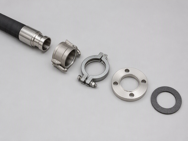
A four-bolt flange takes the thread out of the seal path entirely and uses an O-ring held by two clamp halves. The flange head carries an O-ring in a ring groove, and the head is pressed against a smooth port face by two clamp halves and four bolts. Nothing in the connection depends on thread interference or on a cone. Code 61 is the standard-pressure series of SAE J518, with ISO 6162-1 as the international equivalent, and the whole series is commonly called the 3000 series.
The pressure class is the defining feature. Code 61 is the 3,000 psi (207 bar) series of SAE J518, and its per-size working pressure is highest in the small sizes and falls as the size increases. Take the binding figure from the published rating for that exact size, not from the series name. SAE J518-1 sets the flange head diameter and the bolt spacing, tabulated below. Flange sizes run from -8 (1/2 in) up to -48 (3 in), which is well beyond the practical range of a threaded hose end.
Where Code 61 belongs. Flanges are the normal choice on large-bore suction and return lines. They also suit circuits where the port is on a casting that cannot carry a fine thread, and any joint that has to be oriented before it is tightened. Because the flange can be rotated before the bolts are tightened, a flange connection makes it possible to index a hose end to the routing the machine needs.
What a flange demands in return. The four bolts must be tightened progressively and in a cross pattern, because a flange pulled down on one side will pinch the O-ring and leak. The port face must be flat and unmarked. And the O-ring must sit correctly in the groove before the clamp halves go on; a flange assembled with the O-ring out of its groove leaks at first pressure with no external sign of why.
11. SAE Code 62 Four-Bolt Flange: What Changes at 6,000 PSI?
Code 62 is the high-pressure series of the same flange concept, and it is not interchangeable with Code 61. SAE J518-2 defines it, with ISO 6162-2 as the international equivalent, and the series is commonly called the 6000 series because all sizes are rated at 6,000 psi (414 bar). The difference from Code 61 is physical: the flange head is thicker, the flange outside diameter is larger, and the bolt spacing is wider at every size, and the table below tabulates both series on those dimensions.
The dimensional differences are small but decisive. At -8 (1/2 in), Code 61 has a flange outside diameter of about 1 3/16 inch and a bolt spacing of 1 1/2 inch, while Code 62 has about 1 1/4 inch and 1 19/32 inch. At -24 (1 1/2 in) the gap widens to about 2 3/8 inch against 2 1/2 inch in outside diameter. A Code 61 clamp half will not fit a Code 62 flange head, and the mismatch is often discovered only after the bolts have been started.
Where Code 62 belongs. Code 62 is the correct choice on high-pressure circuits above 3,000 psi (207 bar), on large-bore high-pressure lines, and wherever the system pressure leaves no margin on a Code 61 rating. It is common on mining and heavy construction equipment, on high-pressure test stands, and on large presses.
| Strichstärke | Nominal size | Code 61 flange OD (in) | Code 61 bolt spacing (in) | Code 62 flange OD (in) | Code 62 bolt spacing (in) |
|---|---|---|---|---|---|
| -8 | 1/2 in | 1 3/16 | 1 1/2 | 1 1/4 | 1 19/32 |
| -12 | 3/4 in | 1 1/2 | 1 7/8 | 1 5/8 | 2 |
| -16 | 1 in | 1 3/4 | 2 1/16 | 1 7/8 | 2 1/4 |
| -24 | 1 1/2 in | 2 3/8 | 2 3/4 | 2 1/2 | 3 1/8 |
| -32 | 2 in | 2 13/32 | 3 1/16 | 3 1/8 | 3 13/16 |
Code 61 and Code 62 are so often confused in a store room because they share dash numbers and nominal bores; only the flange outside diameter and the bolt spacing separate them. For the installation sequence and bolt torque behind both series, see our Code 61 and Code 62 split flange installation guide for the tightening pattern and leak-prevention steps.
12. Banjo Fitting: When Is a Hollow Bolt the Right Answer?
A banjo fitting seals with two crush washers around a hollow bolt, and it exists to solve a space problem. The fitting body has an eye, the hollow bolt passes through it and into the port, and fluid travels through the bolt’s cross-drilling and out through the eye. Sealing is by a copper or bonded washer on each side of the eye, compressed against the body and the port face. The eye can be rotated to any angle before the bolt is finally tightened, which is the property that makes a banjo useful.
Where a banjo is the right choice. Banjos sit among the most mis-ordered hydraulic hose fittings types in any catalogue, because they are listed by body style rather than by thread and washer size. They appear where the hose must leave a port at an angle that no fixed fitting can achieve, where the port sits close to another component, and on low-pressure and return circuits. They are common on brake and power steering systems, on fuel and hydraulic return lines, and on compact assemblies where an elbow would foul the surrounding parts.
What a banjo demands in return. The washers are single-use items, and re-using a hardened copper washer is a common cause of a banjo weep. The bolt must be free of a burr at the cross-drilling, and the eye faces must be flat. Vibration is the second cause of failure, because a banjo joint has no positive lock against loosening; our banjo fitting leak guide covers the four failure modes and the fix for each in detail.
13. Crimped and Reusable Hose Ends: Which Termination Belongs on the Hose?
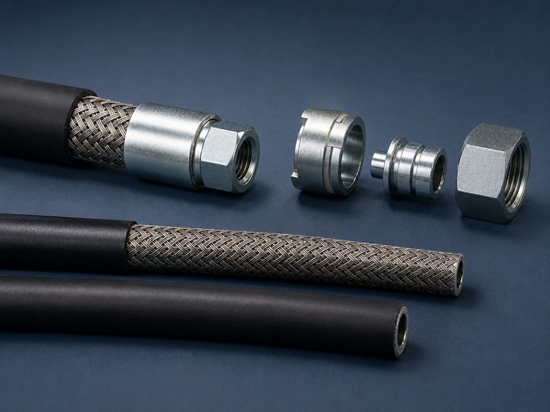
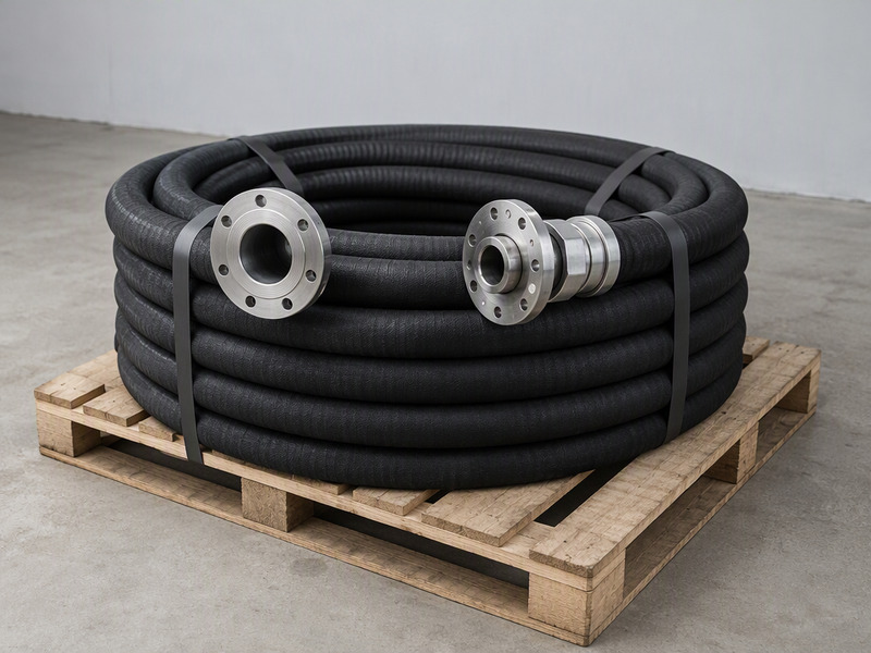
The hose end completes the fitting, and how it attaches decides the assembly’s pressure capability. A crimped end is swaged permanently onto the hose by a machine that compresses the ferrule to a controlled diameter. A reusable end threads or bolts together around the hose and is dismantled and refitted in the field. The port end of both follows one of the families above, so a hose can have a JIC 37° flare at one end and an ORFS at the other, or a metric 24° cone at both.
Both connection methods are defined, and both have a pressure ceiling. Crimped assemblies are covered by SAE J516 for fitting dimensions and ISO 12151 for the international equivalent, and the assembly’s rating is set by the hose construction and the crimp diameter. Reusable ends are rated lower at the same hose size on many constructions, and their rating depends on correct assembly with the matching hose series.
Crimped ends where the assembly is built once. Crimped assemblies give the most consistent result, because the crimp diameter is set by the machine rather than by a technician’s judgment. They are the standard for high-pressure and impulse-rated circuits, and they are the only practical option for spiral-wound hose.
Reusable ends where the repair happens in the field. A reusable end lets a machine be returned to service without a crimper, which matters on a remote site. The trade-off is a lower rating, an assembly that depends on correct technique, and the need to keep the correct hose series on hand.
The skive question sits underneath both. On some hose constructions the cover has to be removed — skived — before the ferrule is fitted, and on others the fitting is designed to bite through an unskived cover. Fitting a no-skive coupling to a hose that requires skiving leaves the ferrule gripping only the cover, and the assembly will fail below its rated pressure. Our guide to skive against no-skive hydraulic hose fittings covers which constructions require which, and what each does to assembly time and cost.
How to Size Hydraulic Fittings in Five Measurements
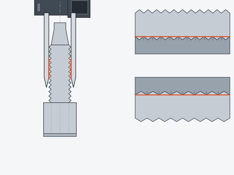
You can size hydraulic fittings of any family with a caliper, a pitch gauge, and five measurements. The method below works on a loose fitting, on an installed port, and on a hose end. It is the same procedure whether the fitting turns out to be JIC, ORFS, BSPP, or a metric 24° cone.
The order matters: measure the thread before the seat, because the thread narrows the family and the seat confirms it. Anyone who learns how to size hydraulic fittings this way stops guessing from a parts catalogue photograph, and a guide to hydraulic fittings is only useful once you can do it.
Step 1: Measure the Thread Outside Diameter
Measure across the crests of a male thread, or the internal diameter of a female thread. Set a digital caliper to inches for a UNF or NPT thread and to millimetres for a metric thread, and record the number to two decimal places.
On a male thread this is the outside diameter. On a female thread it is the minor or core diameter, which is a different figure. Measure in two directions and take the larger reading, because a worn thread will measure undersize across one axis. How to identify hydraulic fittings begins here, because the outside diameter alone eliminates most of the 13 families on the list.
Step 2: Measure the Pitch
Use a gauge, not a ruler, and match the family before the number. An imperial gauge counts threads per inch and a metric gauge measures the distance between crests in millimetres. Both gauges come as a folding set of blades; the correct blade sits flush in the thread with no visible gap and no rocking. A pitch of 1.5 mm is not the same as 16 threads per inch, even though the two are close, so using the wrong gauge system produces a confidently wrong identification.
Step 3: Measure the Seat
The seat is the feature that finally separates two families with the same thread. Sit the fitting on a flat surface and look at the end: a 37° cone, a 30° cone, a 24° cone, a flat face with an O-ring groove, a plain flat face, or a chamfered boss.
Check the angle against a seat gauge or against a known fitting, and check the surface for the continuous witness mark that shows a properly seated cone. For a port, the seat is inside the port and is inspected with a light and a mirror. This is the step where how to identify hydraulic fittings becomes decisive, because the thread alone leaves two or three candidates on the bench.
Step 4: Read the Dash Size Against the Hose
A dash size is nominal, and it describes the hose bore, not the fitting thread. The dash number is the hose inside diameter in sixteenths of an inch: a -8 hose has a nominal 8/16 inch, or 1/2 inch, bore. The fitting thread that goes on a -8 hose is family-specific, which is why the same dash number returns a different thread for JIC, ORFS, and metric:
- -4 hose: 7/16-20 UNF in JIC, 9/16-18 UNF in ORFS, M12 × 1.5 in metric L series
- -6 hose: 9/16-18 UNF in JIC, 11/16-16 UNF in ORFS, M14 × 1.5 in metric L series
- -8 hose: 3/4-16 UNF in JIC, 13/16-16 UNF in ORFS, M16 × 1.5 in metric L series
- -12 hose: 1 1/16-12 UNF in JIC, 1 3/16-12 UNF in ORFS, M18 × 1.5 in metric L series
The metric entry in each line above gives the nearest DIN 2353 L-series size for the same hose bore, as a conversion for ordering — it is not a dash-number equivalent. A metric assembly is ordered by tube or bore diameter, and a metric port is identified by its thread — M14 × 1.5 has a 14 mm thread outside diameter and a 1.5 mm pitch.
Step 5: Confirm Against the Port
The last check is the port, because the fitting has to match both the hose and the machine. Identify the port on the equipment in the same three measurements, then confirm the family.
Two failures are worth guarding against at this stage. A port that has been adapted once often carries an adapter of a different family from the machine’s original specification. A port with a damaged seat will accept the correct fitting and still leak. Record the family and the thread for every port on the machine while you are measuring, and the next replacement will take minutes instead of a shift. That single habit is what makes how to size hydraulic fittings a five-minute job on the second visit.
For the full thread-to-diameter reference across the American and international families, our hydraulic fitting thread identification guide sets out the measurement sequence with the complete size tables. The hose thread size chart covers the hose-side threads that sit outside the hydraulic families. If you would rather have the family confirmed before you order, send the three measurements and a photograph of the seat to our engineering team — most identification requests are answered the same working day.
Where Does the Torque Figure Come From?
Torque is set per size and per material, so it comes from a table rather than from a general rule. Each of the 13 families has a published torque for every thread size, and the figure changes with body material and with whether the joint uses an elastomer. Take the number from the standard or from the coupling manufacturer’s table for the exact size and material you are fitting, and write it on the machine record beside the port family.
A stud end, an adapter and a flange each carry their own figure, and a stacked adapter sequence is limited by the lowest figure in the chain. Feeling for the point where a joint stops turning is not a torque specification on any family in this list.
Hydraulic Fitting Types Chart: Seal Point, Risk and Service Action
A hydraulic fitting types chart is most useful when it is organised by seal point rather than by thread. The thread tells you what will assemble; the seal point tells you what will fail, and how the failure will present. The chart below condenses all 13 fittings into the four columns that matter in a maintenance discussion. Read it alongside the individual sections above as a quick-reference companion to this guide to hydraulic fittings.
| Fitting family | Seal point | Typical failure | Service action |
|---|---|---|---|
| NPT / NPTF | Thread flank | Slow weep at the second or third thread | Re-seal and re-torque; replace if the thread is stretched |
| JIC 37° flare | Metal cone | Weep that worsens with torque | Replace the damaged half and re-torque to specification |
| SAE ORB | O-ring at the boss chamfer | Sudden leak after assembly | Replace the O-ring and check the chamfer for burrs |
| ORFS | Captive O-ring on a flat face | Weep at high pressure or high temperature | Replace the O-ring, clean both faces, re-torque higher |
| BSPP | Bonded washer on a flat face | Weep after a re-build | Fit a new washer; check the port face for scoring |
| BSPT | Thread flank | Weep that returns after re-torque | Re-seal and re-torque to the correct engagement |
| Metric 24° cone | 24° cone with cutting ring | Leak at the cone, or a loose tube | Re-make the connection; inspect the cutting-ring bite |
| JIS 30° flare | 30° metal cone | Weep at the cone face | Replace the deformed half |
| Metric O-ring port | O-ring on a chamfered port | Leak from a damaged or wrong-size O-ring | Fit the correct metric O-ring and inspect the chamfer |
| SAE Code 61 / 62 | O-ring on a flat port face | Leak at one side of the flange | Re-seat the O-ring and tighten the bolts in a cross pattern |
| Banjo | Two crush washers | Weep at the bolt, or a loosened joint | Fit new washers and re-torque |
| Crimped / reusable hose end | Crimp or cage around the hose | Failure at the ferrule under pressure | Replace the assembly; verify the crimp diameter |
Use the failure column as a diagnostic. A leak that gets worse when you tighten points to a deformed metal seat, which is a JIC or JIS symptom. A leak that appears suddenly at first pressure with no previous history points to an elastomer that was displaced on assembly, which is an ORB, ORFS, or BSPP symptom. A leak localised to one side of a connection points to a flange bolt pattern or a cocked tube nut, which is a flange or cutting-ring symptom.
Which Fittings Appear on Lists but Are Not Hydraulic Pressure Connections?
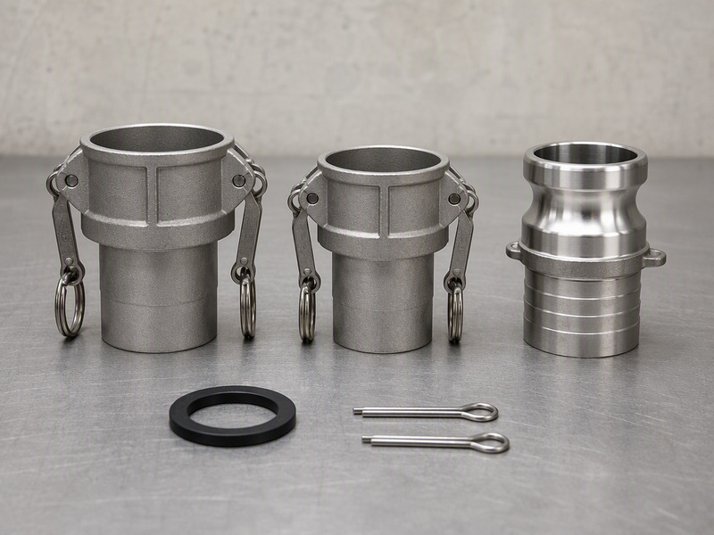
Five families are routinely listed alongside hydraulic fittings and behave nothing like them at pressure. Camlock couplings, flat-face quick couplings, hose barbs, NPSM swivel fittings, and SAE 45° flare fittings all appear in catalogues of hydraulic hose fittings types, and all have a different purpose from a pressure-tight port connection. Knowing where each belongs prevents a low-pressure part from being fitted to a high-pressure circuit, and the five divide as follows:
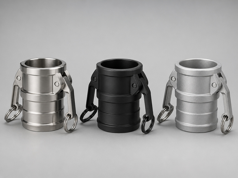
- Camlock (cam and groove): a lever-and-groove coupling for fluid transfer at low pressure, common on tanker, chemical, and agricultural transfer hose. It has no hydraulic pressure rating and is not used on a closed hydraulic circuit.
- Flat-face quick coupling (ISO 16028): a push-to-connect coupling with flush faces that minimise fluid loss on disconnection. Typical ratings run from about 200 bar to about 400 bar depending on size and body material, so it sits in the mid-pressure range rather than at the top of it.
- Hose barb and push-on: a barbed insert gripped by the hose bore, with or without a clamp. It belongs on low-pressure return, drain, and transfer lines only, and its rating is governed by the hose rather than by the barb.
- NPSM: a straight mechanical pipe thread used on swivel nuts at female ends, sealed by a 30° internal chamfer rather than by the thread. It is defined separately from NPT and does not interchange with it.
- SAE 45° flare (SAE J512): a shallower flare that is dimensionally similar to JIC in the small sizes and seals at a 45° seat. It suits low-pressure automotive, refrigeration, and fuel lines, and the 45° cone will not seal against a 37° JIC seat.
The pattern behind all five is the same. Each was designed for a different duty — transfer, quick connection, low pressure, or a specific industry — and the standard reflects that duty. Fitting one of these into a high-pressure hydraulic port produces a joint that may hold at first and will fail under thermal cycling or pressure spikes, which is the worst kind of reliability outcome.
A guide to hydraulic fittings is useful only when it keeps the 13 pressure families separate from transfer and low-pressure couplings. The distinction that matters is the standard the part was built to and the pressure class that standard supports, not the shape of the coupling. Where a catalogue mixes different hydraulic fitting types in one category, sort the list by standard number before comparing anything else.
What Are the Most Common Mistakes When Mixing Different Hydraulic Fitting Types?
Five mistakes account for most cross-family failures, and every one of them is avoidable at the bench. Mixing different hydraulic fitting types is normal and correct on a modern machine, because a single machine often carries three or four families. Mistakes happen when the family is inferred rather than measured. The sequence below is what our assembly team works through on an incoming specification or a field failure:
- 1. Threading by feel. A BSPP male will start into an NPT female, and a JIC hose end will fully thread into an ORB port. Both feel correct and both leak, so measure the thread angle and the outside diameter before accepting a joint.
- 2. Ordering by dash number alone. Two fittings stamped -8 can carry two different threads, because the dash number tracks the hose bore and not the port. Order by thread and family, and treat the dash number as a hose dimension rather than a fitting dimension.
- 3. Re-using elastomer parts. Bonded washers, O-rings, and crush washers are single-use items in pressure service. A re-used washer has already taken a compression set and will not recover the interference the seal depends on.
- 4. Torquing past specification to stop a weep. On a flared joint this deforms the cone, on a tapered pipe joint it stretches the thread, and on a flange it pinches the O-ring. None of the three is recoverable, and all three convert a reseal into a replacement.
- 5. Mixing hose constructions with the wrong coupling series. A no-skive coupling fitted to a hose that requires skiving grips only the cover. The assembly may pass a bench test and still fail in service, because the cover carries no tensile load.
Where a mixed fleet makes the problem worse. A site that runs North American, European and Japanese machinery carries five different families on the same floor, and each one adds a way to pick the wrong part. The discipline that works is to record the port family on every machine at delivery, and to keep the four measurement tools at the bench rather than in a drawer.
Which Hydraulic Fitting Fits Which Port?
The port decides the family and the hose decides the size, and those two decisions are independent. A port is machined to one standard and cannot be changed without re-machining, so the family is fixed by the machine. The hose bore is fixed by the flow the circuit needs, so the size is fixed by the design. That leaves one variable — which hose end to order — and the rest of this list of hydraulic fittings exists to place it correctly.
| Port on the machine | Correct fitting | Common wrong pairing | What happens |
|---|---|---|---|
| 37° female cone (JIC) | JIC 37° flare male | ORB stud, or metric 24° cone | Threads may engage at -6; no seal, immediate leak |
| Chamfered boss with locknut (ORB) | SAE ORB stud with O-ring | JIC 37° flare male | Threads fully, no O-ring contact, leaks at first pressure |
| Flat face with O-ring groove (ORFS) | ORFS male with captive O-ring | JIC or ORB male | Different thread series; will not start beyond two turns |
| Tapered pipe port (NPT) | NPT male with fluid-rated sealant | BSPT male | Starts to engage, stops before seating, weeps |
| Parallel port with flat face (BSPP) | BSPP male with bonded washer | NPT male | Thread angle mismatch; leaks at the washer face |
| Metric 24° cone port | Metric 24° cone stud, L or S series | JIC 37° flare male | Metric thread will not match a UNF port at any size |
| Metric chamfered port (ISO 6149) | Metric stud with O-ring | Metric 60° cone male | Same thread, different seal; leaks at the chamfer |
| Four-bolt flange face | Code 61 or Code 62 flange head | Code 61 clamp on a Code 62 head | Clamp will not seat; O-ring pinched off-centre |
An adapter is a legitimate fix and a common source of new faults. Where a port family cannot be changed, an adapter converts one family to another and lets a hose assembly be standardised across a mixed fleet. The cost is stack height, one more potential leak path, and a change in flow path that matters on suction lines. Two rules keep adapters reliable: use one adapter rather than two in series, and keep the adapter rated at or above the port’s pressure class.
Scope: adapters belong on low-cycle and standard-pressure lines, and a high-cycle position takes the hose end in the correct family. Every additional joint adds a compliance point that pressure spikes can work loose, and a stacked adapter lengthens the lever arm that vibration acts on. Our guide to hydraulic fittings covers the adapter and stud-end ranges that make a conversion possible when it is the right answer.
How Do You Build a Fitting Reference for a Mixed Fleet?
A mixed fleet is managed with one page per machine, not one page per fitting type. A site running North American, European, and Japanese equipment carries JIC, ORFS, BSPP, metric 24° cone, and JIS connections within the same workshop. The reference that works records the port family and thread for every pressure position on every machine, so an order can be placed without measuring again. How to identify hydraulic fittings then becomes a one-time exercise per machine rather than a recurring cost.
The build sequence our application team recommends is short:
- Step 1 — Walk the machine and tag every port. Record the family, the thread, and the hose bore for each pressure, return, and pilot line, using the five-measurement method above.
- Step 2 — Photograph each port with a scale in frame. A caliper laid across the thread gives the next person everything they need, and it removes the guesswork from a phone call.
- Step 3 — Group the record by family rather than by machine. Hold JIC, ORFS, metric 24° cone L and S series, BSPP, and JIS as separate stock lines, because one machine often uses three families.
- Step 4 — Mark the two positions that are unusual. Most machines are predictable, and the exceptions are what cause a stock-out; note them in the record and in the parts list.
- Step 5 — Review the record when a machine changes. A port that has been adapted in the field is a common reason a correct order arrives and does not fit.
The tools cost less than one unplanned stoppage. A digital caliper, an imperial thread pitch gauge, a metric pitch gauge, and a seat gauge cover every measurement in this guide. A hydraulic fitting types chart kept at the bench turns those four readings into a family and a thread in under two minutes, which is how to size hydraulic fittings without pulling the machine out of service.
Metric hydraulic fittings deserve their own line in the reference. Keeping metric hydraulic fittings in a separate stock line, with the L and S series distinguished on the label, removes a common ordering error on a European-built machine.
Use the comparison that caused the problem. On a mixed fleet, the question that comes up most often is the orb vs jic fitting distinction, because the two share their thread sizes and differ only in the seal. Once the reference records which of the two each port uses, the confusion stops. The same page then answers the equivalent question for BSPP against NPT, metric 24° cone against JIC, and Code 61 against Code 62 flange heads.
The port records from a mixed fleet are also the fastest way to close out a repeat leak. A returning failure on one circuit usually shows up in the record as a position that has been adapted, re-fitted, or ordered in two different families over time. Our JIC fitting guide covers the 37° flare family in depth, the NPT against BSP comparison covers the cross-standard thread question, and the reusable against crimped comparison covers the termination decision.
Frequently Asked Questions
What is the most common hydraulic fitting?
JIC 37° flare and ORFS between them cover a large share of mobile hydraulic connections worldwide, with the metric 24° cone third, so any list of hydraulic fittings that omits them is incomplete for mobile equipment. Which one is most common on your site depends entirely on where the machines were built. JIC dominates North American equipment, the metric 24° cone dominates European equipment, and ORFS is now the default on high-pressure circuits from most major manufacturers regardless of origin.
Can I use a JIC fitting in an ORFS port?
No, and the two will not even thread. A -8 JIC uses 3/4-16 UNF while a -8 ORFS uses 13/16-16 UNF, so the threads are different diameters at the same nominal size. The separate orb vs jic fitting question behaves differently: there the two families do share a thread at 9/16-18, and the joint threads fully before leaking because the sealing geometry differs.
What is the difference between ORFS and ORB?
ORFS seals with a captive O-ring against a flat face, and ORB seals with an O-ring against a chamfered boss. ORFS uses its own larger thread series, while ORB shares the straight UNF threads used by JIC. ORFS is the higher-pressure option at 6,000 psi (414 bar) capability, and ORB is the more compact one because it needs a shorter stud.
How do I identify an unknown hydraulic fitting?
Measure three things: the thread outside diameter with a caliper, the pitch with a gauge, and the seat with a seat gauge or a known reference fitting. Those three measurements place the fitting in one family and one size. Add the thread angle if the measured pitch matches both BSP and NPT in the common sizes. Knowing how to identify hydraulic fittings this way is faster than photographing the fitting and waiting for an answer, and it works with no signal on site.
Are NPT and BSP interchangeable?
No. NPT is cut at 60° and BSP at 55°, and at 1/2 inch and 3/4 inch both use the same pitch of 14 threads per inch. That combination lets the two start to engage and then stop before the joint seats. At 1 inch the pitches also differ, with BSP at 11 threads per inch against 11.5 for NPT.
What does a dash size mean on a hydraulic fitting?
A dash size is the nominal hose bore expressed in sixteenths of an inch, which is where the number in -4, -8 and -12 comes from. It does not describe the fitting thread, and the same dash number carries a different thread in each family. Metric hose and metric ports are identified in millimetres instead, and dash numbers do not apply to them.
Which hydraulic fitting is best for high pressure?
ORFS and the high-pressure flange series carry the highest ratings in common use, with ORFS rated to 6,000 psi (414 bar) and Code 62 flanges rated to 6,000 psi across their size range. The metric 24° cone S series and the SAE ORB also reach high pressure, with the actual figure set by size and material. Above the rating of a threaded connection, flanges become the practical choice.
Why does a brand new hydraulic fitting leak?
Four causes account for almost all first-fit leaks: a displaced O-ring, a damaged cone, a re-used washer, and under-torque on a face-seal connection. A fitting that leaks immediately at first pressure almost always has an elastomer that was dislodged during assembly. A fitting that weeps after a few hours usually has a seat defect or a thread mismatch.
Can I re-use a hydraulic fitting?
Re-use the metal body only after inspecting the seat and the thread. Replace every elastomer. An O-ring or a washer seals by deforming, and a second installation starts from the deformed shape rather than a new one. Crimped hose ends cannot be re-used on a new hose, because the ferrule is permanently deformed. Reusable ends can be dismantled and refitted, but only with the matching hose construction.
What is the difference between a hydraulic fitting and a hose end?
A hose end terminates the hose, and a fitting connects that end to a port. A single assembly usually has both, with the hose end at the hose side and a port connection at the other. In catalogue terms both are hydraulic hose fittings types, and the port connection follows one of the families above, so a hose can carry a JIC end and an ORFS end on the same assembly.
Which fitting families should a mixed fleet keep in stock?
JIC, ORFS, BSPP, metric 24° cone L and S series, and JIS 30° cover most of the list of hydraulic fittings a mixed fleet needs. Stock by family and thread, because one manufacturer often uses more than one family across a product range. Keep the families visually separated on the shelf, since mixing different hydraulic fitting types in one bin is what turns a correct order into a wrong pick.
Do hydraulic fittings need sealant?
Tapered threads need it, and straight threads do not. NPT and BSPT seal on the thread flank, so a fluid-rated sealant or tape is normal practice. JIC, ORFS, ORB, BSPP, and every metric family seal on a cone, an O-ring, or a washer, and adding sealant to those joints does nothing useful and can contaminate the circuit.
Sourcing a Complete List of Hydraulic Fittings as One System
The thirteen families in this list of hydraulic fittings are not alternatives to each other. A single machine typically carries three or four of them, and the assembly has to be built so that each end matches the port it will meet. That is why we treat fitting selection and hose assembly as one specification problem rather than two.
HENGHUA manufactures hydraulic hose assemblies and the fittings that terminate them, for construction, mining, agricultural, and industrial equipment, and supplies equipment builders and distributors worldwide. The range covers all 13 families in this list of hydraulic fittings:
- JIC 37° flare, ORFS, SAE ORB, BSPP and BSPT
- the metric 24° cone in both L and S series, and JIS 30° flare
- metric O-ring ports, and SAE Code 61 and Code 62 flanges
- banjo bodies and bolts, and crimped or reusable hose ends
Representative parts include the JIC 37° flare male stud end, the ORFS male O-ring seal end, and the banjo body and bolt for ports where space behind the fitting is the limiting factor.
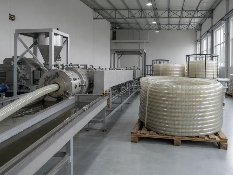
Every assembly is crimped on matched hose and coupling systems with a verified crimp diameter and pressure tested before shipment, with production records traceable to the batch. Because extrusion, wire braiding, fitting machining, crimping, and impulse testing all happen in house, we can support the specification stage as well as production.
That support covers the questions that a parts catalogue cannot answer. Two situations are worth sending to us. The first is a specification for a mixed fleet, or a port being converted from one family to another. The second is a leak that keeps returning to one circuit. For either, send the port thread, the hose size, the working pressure, and the fluid. Our engineering team will confirm the correct family, the correct thread, and the correct assembly for each position.
How Do I Keep One Fleet Interchangeable Across Three Suppliers?
Fix the specification, not the supplier list. Publish one family, one thread, and one hose construction per circuit, and require every supplier to build to that specification with matched hose and coupling systems. Where two suppliers are used for the same position, verify the crimp diameter and the fitting seat before the assemblies enter stock. A visually identical fitting from a different source removes the dimensional relationship the crimp depends on.
For a quote on fittings or assemblies, contact our engineering team with the thread size, the hose bore, and the system working pressure. We can also work through the rest of this list of hydraulic fittings against a machine you are rebuilding. We will come back with the matching family and the assembly specification, and we can supply hydraulic hose and fittings from the same production batch for any fleet standardisation project.
Two of our guides cover the system level. The hydraulic hose and couplings guide explains the hose-to-fitting match, and the hydraulic hose assembly and crimping guide explains the crimp process and the testing behind it. The SAE, DIN, ISO and GB standards comparison sets out how the standards behind each family relate to one another.
Thread sizes, standards, and pressure classes in this guide are reviewed on a quarterly cycle; the 13 fittings and the comparison charts were last checked against current published standard editions on 19 September 2026.
About the author: Written by the HENGHUA Engineering Team — hose and fitting application engineers supporting hydraulic fitting selection, assembly crimping, and impulse testing for construction, mining, agricultural, and industrial equipment customers. Every thread dimension and pressure class in this guide reflects our own machining, assembly, and field service records across SAE, ISO, DIN, and JIS fitting families.
 English
  Spanish
  Portuguese
  French
  German
  Arabic
  Russian
  Indonesian
  Japanese
  Korean