

How long do hydraulic hoses last? Hydraulic hose service life is a range rather than a date, and on a condition-based hydraulic hose maintenance routine the honest range is one to two years on severe mobile duty, four to six years on standard mobile equipment and five to ten years on cool, low-cycle industrial duty — and no calendar figure ever overrules what the hose looks like in service. A hose is a wear part, not a pipe: its service life is consumed by pressure cycles, heat, abrasion, flexing and fluid chemistry, so the same part number can be finished in twelve months on a hot quarry excavator and still be sound after ten years on an indoor power unit. The routine that produces those ranges has three moving parts — a pre-shift visual check on every hose, a detailed inspection every 400–600 operating hours or three months (whichever comes first), and a documented replacement decision based on condition, duty and age. This guide covers what actually limits hose service life, how to calculate a replacement interval for your own machines, how to convert an impulse rating into operating hours, the maintenance tasks that measurably extend life, how storage affects the replacement decision, end-of-life criteria, inspection records, the cost case for planned replacement, and the safety consequences of running a hose one shift too long.
Figure 1. A pre-shift check takes two to three minutes per machine and is the cheapest point at which hydraulic hose maintenance can catch a problem.
1. How Long Do Hydraulic Hoses Last? Hydraulic Hose Service Life at a Glance
Planning ranges rather than a single number. Published figures run from one to two years on severe mobile duty (heat, abrasion, high cycle) through four to six years on standard mobile equipment to five to ten years on cool, low-cycle industrial duty, and a safety-critical circuit is replaced on the OEM interval — never beyond ten years. Hydraulic hose service life is the number of operating hours, or in practice the number of months and years, that an assembly can be expected to remain safe in a specific application, and it is set by five wear mechanisms acting together. The same hose can therefore be finished in twelve to twenty-four months on a hot, high-cycle excavator boom while a sister assembly of the same part number is still sound after ten years on a cool power unit, which is why published hydraulic hose life expectancy figures are averages that no individual machine has to obey. Table 1 sets out the planning ranges by duty class, the hours each class runs, what ends life first and the inspection cadence each class needs.
Table 1. Hose service life planning ranges by duty class (planning bands for budgeting and inspection scheduling, not warranty terms)
| Duty class | Typical annual hours | Planning service life | What ends life first | Inspection cadence |
|---|---|---|---|---|
| Light industrial, cool, steady load | 1,000–2,000 | 5–10 years | Cover aging, mild flex fatigue | Monthly visual, annual detailed |
| Standard mobile equipment | 1,500–2,500 | 4–6 years | Flex fatigue near fittings, abrasion | Weekly visual, 3-month detailed |
| High-pressure continuous duty | 2,000–4,000 | 2–3 years | Pressure-cycle fatigue of the wire | Daily visual, monthly detailed |
| Severe duty: heat, abrasion, high cycle | 3,000–6,000 | 1–2 years | Abrasion exposing reinforcement, heat aging | Daily visual, monthly detailed plus event-driven checks |
| Safety-critical systems (brakes, steering, lifting) | Any | OEM interval; where none is published, 10 years is the industry practice ceiling for an installed safety-critical assembly. What is borrowed from SAE J1273 is the method — age control counted from the cure date — not the number: its 40-quarter figure is a stock-control value for unused hose, not a service limit | Consequence of failure, not the hose condition alone | Per OEM and regulatory schedule |
Two honest caveats apply to the planning ranges above. First, they are budgeting and inspection-scheduling ranges for a correctly specified hose, not warranty statements — a hose is only warranted to the specification and conditions it was sold against. Second, the ranges assume the hose was correctly selected, correctly crimped and correctly routed in the first place; a hose that is one size too small, twisted at installation or routed over a sharp edge can fail inside its first month regardless of class — the STAMPED selection method is a quick way to check that the original selection was right, and working pressure versus burst pressure explains how much margin the printed numbers really represent.
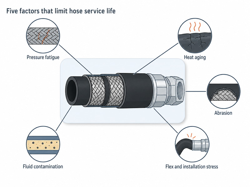
Figure 2. Five mechanisms limit hose service life. Whichever one dominates in an application is the one the maintenance programme should be aimed at.
2. Why Published Hydraulic Hose Service Life Figures Disagree
Ask five suppliers how long a hydraulic hose lasts and you will get five different answers, all defensible, because the figures are answering slightly different questions. That inconsistency is the single biggest source of confusion about hose service life, so it is worth untangling before you set an interval.
Table 2. Why published hose life figures differ: figure, basis and correct use
| Published figure | What it actually measures | Correct use |
|---|---|---|
| Up to 10 years from the cure date for bulk rubber hose (SAE J1273 age control, 40 quarters) | Shelf-life allowance of correctly stored, unused rubber hose under a recognised age-control basis | Defining when a spare assembly or a reel must be scrapped — not how long it survives in service |
| 5–7 years shelf life (distributor practice; ISO 8331 gives 4 years in bulk and 2 years once assembled) | Practical storage life for stock held in an ordinary warehouse | Practical planning figure for stock in a normal store room |
| Effectively unlimited shelf life for thermoplastic hose (thermoplastic supplier guidance; ISO 2230 covers the storage of rubber products, not thermoplastics) | Storage life of thermoplastic hose held under controlled conditions | Justifying longer stock holding for thermoplastic hose — still subject to a first-in, first-out rule |
| 4–6 years in service | Service life on standard mobile duty with regular inspection | Setting a review point, not a hard replacement date |
| 2–6 years on standard mobile to high-pressure continuous duty, or 1–2 years on severe duty (this range is the union of the standard-mobile 4–6 year and high-pressure-continuous 2–3 year bands of Table 1, split out on Table 1’s severe-duty row) | Service life where pressure cycling, heat and abrasion are all present | Fleet planning and stock holding for construction, mining and demolition machines |
| 200,000 to 1,000,000 impulse cycles | Laboratory fatigue life at 133% of rated working pressure, not calendar time | Comparing hose constructions and qualifying a supplier — see Section 5 (How Do You Set a Hydraulic Hose Replacement Interval?) to convert it into hours |
The pattern behind the disagreement is simple, and it explains why hydraulic hose lifespan figures circulating online rarely agree with one another. Shelf life is counted from the cure date — the date of manufacture marked on the hose — and is consumed whether or not the hose does any work. Service life is counted from installation and is consumed by work. Every published number is one of those two, quoted against a set of storage or operating conditions that the reader has to supply for themselves. When two datasheets conflict, compare the basis before the number: is it shelf life or service life, which date does the clock start from, what fluid temperature and pressure amplitude does it assume, and is the limit continuous or intermittent?
3. What Is the Difference Between Hydraulic Hose Service Life, Shelf Life and the Inspection Interval?
Confusing these three numbers is the most common analytical mistake in hydraulic hose maintenance, and it usually shows up as hoses replaced too early on one machine and too late on another. Hydraulic hose shelf life, service life and the inspection interval are three separate clocks, and treating them as a single clock is what produces both errors.
Table 3. Three numbers that are routinely confused
| Number | Clock starts | Consumed by | Typical value |
|---|---|---|---|
| Shelf life | Cure date | Time in storage, heat, ozone, UV, humidity | 5–10 years for rubber hose; longer for thermoplastic hose in controlled storage |
| Service life | Installation date | Pressure cycles, flex cycles, heat, abrasion, fluid exposure | 1–2 years severe duty to 5–10 years light industrial duty |
| Inspection interval | Previous inspection | Nothing — it is a schedule | Daily visual; detailed every 400–600 h or 3 months; annual audit |
The practical consequence: a hose’s shelf life and its service life run back-to-back, and the total from cure date to end of service is what actually matters. An assembly made three years ago that has been sitting in a hot, sunlit yard has already spent much of its allowance before it is installed. That is why marking and reading the cure date — not just the installation date — is part of good practice, and why a hose whose age or history is unknown should be treated as being at the end of its service life rather than at the start of it. Reading the layline for size, pressure, standard code and replacement information takes seconds and tells you what margin the assembly was built with.
4. What Ends a Hydraulic Hose’s Service Life? Five Mechanisms
Every hydraulic hose failure traces back to one or more of five mechanisms. Knowing which one dominates in your application is what turns generic advice into a maintenance plan.
4.1 Why Does the Wire Reinforcement Run Out of Cycles?
A hydraulic hose flexes under pressure. Each pressure rise and fall strains the steel wire reinforcement, and repeated strain eventually cracks individual wires — a classic fatigue failure that starts internally and gives no outward warning until the bulge or the burst appears. Hose qualification standards exist precisely for this: the wire-braid constructions specified in SAE J517 and their international counterpart ISO 1436 are impulse-tested at 133% of rated working pressure for a required number of cycles, the test procedures are specified in SAE J343 and ISO 6605, and performance-based standards such as ISO 18752 grade hose by impulse cycle count rather than by construction alone. The cycle figures themselves are given in Table 2, where they are marked as a laboratory fatigue-life basis rather than a calendar life.
The engineering insight worth carrying into maintenance planning is that fatigue damage accumulates as a power law rather than a straight line; our explainer on why impulse life testing determines durability sets out how those cycle numbers are produced. Our own laboratory position, based on impulse testing of production-representative assemblies, is that an impulse cycle at 133% of rated working pressure is a materially harsher cycle than a working cycle at the rated pressure — which is why a qualified hose survives far more real pressure cycles than the test number suggests, and equally why occasional severe pressure spikes do disproportionate damage. A relief valve that keeps system peaks off the hose is a service-life investment.
4.2 Why Is Heat the Fastest Clock on a Hose?
Elevated fluid temperature accelerates the chemical aging of both the nitrile (NBR) tube and the outer cover. Rubber hardens, loses elasticity and begins to crack; the tube can crack from the inside, sending rubber fragments into the system. Suppliers commonly quote a rule of thumb that sustained operation about 10 °C above a hose’s rated limit roughly halves its expected service life. Treat it as a planning guide that holds across moderate excursions rather than at the extremes of the compound’s range, and not as a warranty figure; the direction, however, is beyond dispute: heat is the most controllable input to hose service life, and every 10 °C removed from the fluid is measurable life added back.
Heat also interacts with pressure, which is why temperature-rated hose selection and the maintenance programme have to be decided together. Above a hose’s continuous temperature limit its published working pressure has to be derated, so a hot circuit is no longer the pressure rating printed on the layline. Running a hose at both its maximum pressure and its maximum temperature at the same time is the fastest way to consume its life.
4.3 Why Is Abrasion the Leading Cause of Hose Failure?
Abrasion — the cover rubbed away by structure, bracketry, gravel or another hose until the reinforcement is exposed — is described by NAHAD (Association for Hose and Accessories Distribution), the hose industry’s own safety body, as the leading cause of hose failure, and it matches what we see in returned assemblies. Once the cover is breached, the wire corrodes, and a corroded wire loses fatigue strength long before its cycle allowance is used up.
Abrasion is also the most preventable mechanism. Most abrasion failures happen at a handful of predictable contact points that are visible during a walk-around: where a hose passes through a bulkhead or a pivot, where two hoses cross, where a hose lies on a chassis rail, and near the fitting where movement is greatest. Protection sleeves, spiral wraps and guards at those points are inexpensive compared with the alternative, and rerouting to eliminate contact entirely is better still — our guides to hose abrasion protection and sleeve selection and to hose routing mistakes that cause failures cover the selection and the fixes.
4.4 How Do Flex and Installation Stress End a Hose’s Life?
Over-bending, bending too close to the fitting, kinking, and twisting are installation faults that shorten service life from day one. Two rules matter most. First, the minimum bend radius is measured from the inside edge of the bend, not from the centreline of the hose, so a bend that looks acceptable by eye can already be outside specification. Second, a hose must be installed in the plane in which it naturally bends; twisting a hose into position rather than routing it into position is associated in hose-industry testing with a disproportionate loss of service life — a small twist consumes a large share of the assembly’s allowance long before the cover shows anything. If a layline spirals around the hose instead of running straight along one side, the hose is twisted.
4.5 Can Fluid Chemistry Kill a Hose From the Inside?
The tube has to be compatible with what flows through it — the inner tube compound is the most application-specific choice in the whole assembly. Use the wrong compound and the tube swells, softens or blisters from the inside — a failure mode that no amount of external inspection will catch early. The same discipline applies to the fluid and the components around the hose: particle contamination in the oil is the dominant cause of hydraulic component wear, with industry cleanliness guidance attributing the majority of mechanical wear to particles and noting that oil held at an ISO 4406 cleanliness code of 18/16/13 instead of the 16/14/11 a typical mobile system is specified to can halve hydraulic component life. A clean system means fewer pressure spikes from sticking valves, less internal abrasion and less heat, all of which lengthen hose service life.
5. How Do You Set a Hydraulic Hose Replacement Interval for Your Own Machines?
The industry convention for mobile equipment — inspect at 400–600 operating hours, or on a quarterly cycle, whichever comes first — is a sensible default, but it is a floor rather than a plan. A hydraulic hose replacement interval should be derived from the duty a position actually sees, because the same part number can last three years on a cooled industrial unit and eleven months on a hot, high-cycle boom; that is why asking how long do hydraulic hoses last returns a range rather than a figure. To turn the convention into a schedule for a specific machine, apply four factors to a base interval. The model below is a planning tool: it is not a warranty, and a hose that fails a condition check is replaced regardless of what the numbers say.
5.1 The four-factor interval model
Planned review interval (hours) = Base interval × Pressure factor × Temperature factor × Environment factor × Cycle factor
Start from a base interval of 2,000 operating hours for standard mobile duty, then multiply by the factors that match the application. Any hydraulic hose replacement interval produced this way is an inspection and review trigger, not an automatic replacement order — condition still decides.
Scope of this model. The four-factor model applies only to hoses already correctly specified for their duty — ones whose working pressure and temperature rating cover the system’s continuous limits. If fluid temperature runs continuously above the hose’s continuous limit, or system pressure exceeds the rated working pressure, the correct action is to change the specification rather than to shorten the review interval. Use the model to schedule reviews; use the specification to stay inside the limits.
Table 4. Planning factors for a hose replacement interval (illustrative, not a warranty)
| Input | Condition | Factor | Reason |
|---|---|---|---|
| Pressure utilisation | Runs at or near rated working pressure for long periods | 0.7 | Fatigue damage accumulates as a power law with pressure amplitude |
| Pressure utilisation | Comfortable margin below rated working pressure, well-damped system | 1.0 | Amplitude stays low, cycles are cheap |
| Fluid temperature | Within the rated range with margin | 1.0 | Aging proceeds at the compound’s design rate |
| Fluid temperature | Measured excursion above the continuous limit but inside the manufacturer’s derated rating | 0.6 | Accelerated tube and cover aging; the pressure rating is also derated |
| Fluid temperature | Sustained above the continuous limit | — (out of scope) | Change the specification rather than the schedule — see the scope note above and Section 4.2 |
| Environment | Abrasive: mining, demolition, gravel, continuous contact | 0.7 | Cover wear is the leading failure cause; exposed wire corrodes |
| Environment | Outdoor, UV and ozone exposure, no contact points | 0.9 | Cover aging from the outside, without mechanical wear |
| Environment | Indoor, clean, protected routing | 1.0 | No synergistic external damage |
| Cycle rate | High-cycle operation: continuous movement, many pressure pulses per hour | 0.7 | Consumes impulse allowance quickly — see the worked example |
| Cycle rate | Low-cycle, steady-state operation | 1.0 | Wire fatigue accumulates slowly |
5.2 Worked example: a high-cycle, hot, abrasive machine
Take a hydraulic excavator running a boom hose in an abrasive quarry: high pressure utilisation during digging (0.7), fluid temperature running at the top of the manufacturer’s derated range because the cooler is marginal (0.6), abrasive environment with contact points (0.7), and high cycle rate (0.7).
Planned review interval = 2,000 × 0.7 × 0.6 × 0.7 × 0.7 ≈ 412 operating hours.
A 412-hour review interval sits at the bottom of the 400–600-hour convention band, and it lands in the severe-duty band of Table 1 despite the same hose being rated for years of service on a cooler, gentler machine. Run the same model for a stationary industrial power unit and the calculation returns 2,000 × 1.0 × 1.0 × 1.0 × 1.0 = 2,000 hours, with a far longer calendar life because the machine runs fewer hours per year.
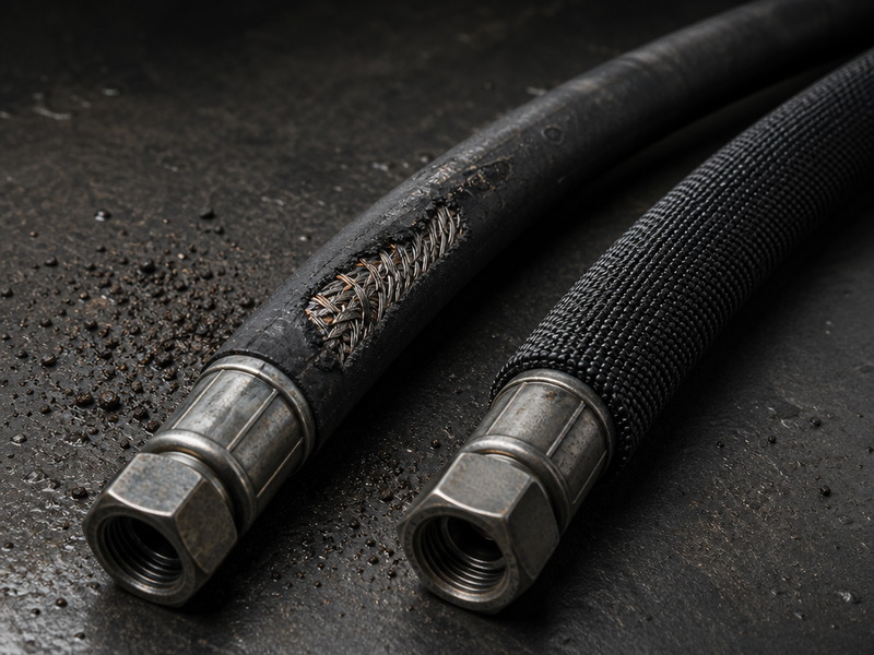
Figure 3. Cover wear that exposes the wire reinforcement ends the service life of the assembly immediately. A sleeve fitted before the damage starts is the cheaper intervention.
Want these factors worked for your own machine? Send us the machine type, the hose position, the system pressure and the fluid temperature you measure, and our engineering team will return a worked review interval and the specification it implies — no obligation.
5.3 Converting an impulse rating into operating hours
Impulse data is the reasonableness check that turns a catalogue number into a schedule, and the conversion needs only the cycle rate the machine actually generates: cycles per hour = cycles per minute × 60.
Worked conversion. A boom circuit that cycles 20 times per minute — an example parameter, to be replaced with the rate you measure on your own machine — runs 20 × 60 = 1,200 pressure cycles per hour. A hose qualified for 200,000 cycles at 133% of rated working pressure therefore exhausts its published impulse allowance in about 167 hours of that duty (200,000 ÷ 1,200 ≈ 167 h), while a hose qualified for 1,000,000 cycles lasts about 833 hours (1,000,000 ÷ 1,200 ≈ 833 h).
Compare those figures with the review interval from the worked example in Section 5.2. The four-factor interval for that machine is 412 hours and the impulse allowance for the entry grade is 167 hours, so the position is inspected every 167 hours — the impulse allowance governs. Where that figure is far shorter than the intervals the machine needs between planned stops, the specification rather than the schedule is what has to change: move to a higher cycle grade so the allowance covers the duty, and re-run the same comparison in hours. That is why we publish impulse cycle data with our assemblies rather than only a pressure rating, and the test procedures behind those numbers are the ones specified in SAE J343 and ISO 6605. Our hydraulic hose testing standards guide sets out how hydrostatic, burst and impulse testing relate to the numbers printed on the layline.
6. The Maintenance Tasks That Actually Extend Hydraulic Hose Service Life
Most of what determines hose service life is decided before the hose carries its first pressurised oil, which is why preventive maintenance on hydraulics is mostly engineering rather than repair work. The eight measures ranked below — routing, support, twist elimination, contact-point protection, operating below the limits, fluid cleanliness, crimp discipline and correct spares storage — are ordered by the contribution each one makes to hose service life in our own returned-assembly and field-failure analysis. This section stays on the hose itself; for whole-system preventive maintenance, troubleshooting of hydraulic faults and lifecycle cost reduction across the machine, see our guide to hydraulic system troubleshooting and preventive maintenance.
6.1 Get the routing right first
Correct routing prevents abrasion, over-bending and flex fatigue at the same time. Route the hose to follow its natural bend plane, keep it away from sharp edges, hot surfaces and exhaust components, provide enough slack for the hose to contract and extend as pressure changes, and avoid bending it in more than one plane between two points. Never pull a hose straight into a fitting — if it takes force to reach the port, the routing is wrong, not the hose.
6.2 Support the hose so it cannot move under load
Pressure change makes a hose grow and shrink in length, and a hose that is allowed to move will chafe against whatever is next to it. Support and clamp the assembly so that the movement happens in the flexing plane rather than against structure, and check during a running inspection that no hose is sawing against a neighbouring hose, a bracket or a frame rail. Independent movement of a fitting relative to the hose is a replacement trigger, not a tightening job.
6.3 Eliminate twist at installation
Twist is the quiet one. A twisted hose still looks fine, but the reinforcement is working against itself, fittings are pre-stressed and service life falls sharply. The check is straightforward: read the layline along the hose. If it runs straight from end to end, the installation is twist-free; if it corkscrews, the hose is twisted and should be released and refitted.
6.4 Protect every predictable contact point
Abrasion protection is a consumable that extends the life of a much more expensive component. Fit sleeves, spiral wraps or guards wherever a hose passes through a bulkhead, crosses another hose or rests on structure, and give priority to the last 300 mm before each fitting where the hose has least freedom to move. Protection selected for the actual threat — chafing, impact, molten splash or heat — works; generic wrapping often does not.
6.5 Operate below the limits, not at them
A hose run continuously at rated working pressure and at the top of its temperature range is using up its allowance at the maximum rate the specification permits. Where the application allows, specify the next size or next construction up so the hose runs at a comfortable fraction of its rating, fit a relief valve or accumulator to damp pressure spikes, and fix cooling problems at the source — an undersized cooler is paid for in hose and hydraulic component life, not just in oil temperature.
6.6 Keep the fluid clean and the tube compatible
Internal wear and tear is invisible from outside. Particle contamination drives component wear, pressure spikes and heat, so filter to the system manufacturer’s specification, sample the oil on a schedule, and treat the ISO 4406 cleanliness code as a maintenance KPI rather than a laboratory curiosity. Confirm the tube compound against the fluid actually in the system — mineral oil, water-glycol, biodegradable ester or phosphate ester all place different demands on the inner tube — and re-check after any fluid change. Where an assembly has been used for cleaning, flushing or temporary service, clean it to a defined cleanliness level before returning it to the machine.
6.7 Crimp, torque and never mix sources
An assembly is only as good as its crimp, and the crimp process and its testing standards are what separate a matched assembly from a collection of parts. Use hose, fittings and ferrules from matched sources, and follow the manufacturer’s crimp settings and equipment. Mixing components from two manufacturers requires written approval from both suppliers, because the assembly is engineered as a matched system — a rule that SAE J1273 and ISO/TS 17165-2 state explicitly. Verify termination torque on a schedule: torque loss from vibration and thermal cycling is a common route to a weeping fitting and a failed inspection.
6.8 Store spares properly so they arrive with their full life intact
Because shelf life and service life are separate allowances, a spare assembly that has spent five years on a sunlit shelf starts its working life with a large part of its allowance already spent. Stock rotation is therefore part of hydraulic hose maintenance rather than part of purchasing, and Section 8, on storage, sets out what that means for the replacement decision.
7. Hydraulic Hose Inspection: The Cadence That Protects Service Life
A hydraulic hose inspection programme does not extend service life — it tells you where you are in it, at the cheapest possible point of intervention. The fleet convention runs on four levels — a visual check before each shift on every hose, a detailed inspection keyed to either operating hours or the calendar (400–600 h or three months, whichever comes first), a running inspection under load, and an annual audit of age, records and interval factors. Table 5 sets out who performs each level, what it looks for and what it produces, and it exists because a two-minute visual check catches the majority of conditions that lead to a mid-shift failure.
Table 5. Hydraulic hose inspection cadence and what each level is looking for
| Level | Frequency | Who | Focus | Output |
|---|---|---|---|---|
| Pre-shift visual check | Every shift, before operation | Operator | Leaks, chafing, cover damage, kinks, exposed wire, fitting movement | Pass, or tag out and report |
| Detailed inspection | Every 400–600 operating hours or 3 months, whichever comes first | Maintenance technician | Full hose and fitting survey, bend radius and clamp condition, routing and contact points, protection sleeve wear | Written record per hose position |
| Running inspection | During operation, at a safe distance | Technician | Hose movement, twisting under pressure, pulsation, hot spots, chafing that only appears under load | List of positions to re-route or protect |
| Annual audit | Yearly | Maintenance engineer | Age and interval review against records, failure-mode trend, stock and shelf-life review, interval adjustment | Updated replacement plan and interval factors |
Three practical points make the difference between an inspection programme that works and one that ticks boxes.
Depressurise before you touch anything. Every detailed inspection starts with the machine shut down, pressure released and, where the work involves opening the system, lockout/tagout applied. Never handle a pressurised hose to look for a leak.
Use a target, never a finger. Suspected pinhole leaks are found with a piece of cardboard, wood or paper held at a distance — a method that protects the inspector and still localises the leak reliably.
Write it down. A daily check that produces no record cannot support an interval decision, cannot demonstrate due diligence, and cannot show that a particular position fails repeatedly. Section 10 (Hydraulic Hose Tagging and Records) covers what to record.
For the field procedure itself — the twelve-point daily checklist, the fifteen failure signs with the action for each, and the step-by-step technician procedure — our companion guide on hydraulic hose inspection checklist and failure signs covers the detail. This section sets the cadence; that guide is the working document to print and carry.
Table 6. Regulatory and recommended-practice hooks for hose inspection records
| Requirement | Applies to | What it means for hose maintenance |
|---|---|---|
| MSHA 30 CFR 56.14100 / 57.14100 | Self-propelled mobile equipment at surface and underground mines in the United States | Equipment must be inspected before being placed in operation on a shift, and safety defects must be corrected before the equipment is used |
| OSHA 29 CFR 1910.147 (lockout/tagout) | Servicing and maintenance of machines where unexpected energisation or release of stored energy could injure | Pressure in a hydraulic accumulator or line is stored energy: follow the site’s lockout/tagout procedure before opening a system |
| US DOT 49 CFR 393.45 | Brake tubing and hose on commercial motor vehicles | Brake hose condition, routing and security are explicitly regulated — inspect and document accordingly |
| SAE J1273 / ISO/TS 17165-2 | Recommended practices for hydraulic hose assemblies | The reference documents for selection, routing, fabrication, installation, replacement, maintenance and storage — worth reading in full if you write hose standards for a fleet |
| ISO 4413 | Hydraulic fluid power — general rules and safety requirements for systems and components | System-level safety requirements that frame inspection intervals on safety-critical hydraulics |
| DGUV Regel 113-020 (edition October 2017, following DIN 20066) | Hydraulic hose lines on machinery in Germany and, by adoption, several EU operators | Inspection by a competent person at least every 12 months; where the operator’s risk assessment identifies severe duty or a safety-critical circuit, the assessed interval is shorter |
8. How Does Storage Affect Hydraulic Hose Shelf Life and Service Life?
Storage discipline protects an allowance that is being spent whether or not the hose does any work: heat, ozone, ultraviolet light, humidity, solvents and permanent bending stress all age rubber. That is why ISO 2230, which covers the storage of rubber products, and ISO 8331, which covers the selection, storage, use and maintenance of hose assemblies, both treat storage conditions as a life-limiting variable rather than a housekeeping matter. The standard limits are set by ISO 8331: storage temperature should stay below +25 °C where the store allows it and never above +50 °C, hose should be kept out of direct sunlight and away from ozone sources such as electric motors and welding sets, and stock should rotate first in, first out. A store-room ceiling of +38 °C (+100 °F) is quoted by distributors as a practical working target for hot climates; it is a figure for an ordinary warehouse, not the standard limit.
What matters for a replacement decision is the arithmetic between the two clocks. Hydraulic hose shelf life is counted from the cure date and is consumed in the store; service life is counted from installation and is consumed by work. They run back-to-back, so a spare assembly that has spent five years on a sunlit shelf reaches the machine with a large part of its allowance already spent. Confirm the cure date before a hose enters service: where the cure date or the storage history cannot be established, treat the assembly as being at the end of its shelf life and route it to non-critical, low-pressure service only, never to a safety-critical circuit.
The stage-by-stage storage procedure — coil handling, racking, packaging, fitting protection, pre-warming after cold storage and the full stock-rotation routine — belongs to our dedicated guide to hydraulic hose shelf life and storage rules, which carries the storage conditions in full. This article keeps only the part of storage that changes the replacement decision, because the two clocks above are what the interval model in Section 5 is built on.
9. When Should You Replace a Hydraulic Hose? End-of-Service-Life Criteria
The decision to replace is a condition decision supported by age and interval data — never a calendar date on its own. Replace when a condition in Table 7 is present, when the position is past its review interval, or when the age and history cannot be established, whichever comes first: a Table 7 condition ends a hose’s service life immediately.
Table 7. End-of-service-life conditions and the required action
| Condition observed | Why it ends service life | Action |
|---|---|---|
| Any active leak, including a pinhole weep | Leak path will enlarge; injection hazard to anyone nearby | Stop operation, depressurise, tag out, replace the assembly |
| Exposed wire reinforcement through the cover | Wire is already corroding; fatigue life is lost | Replace |
| Blister, bulge or soft spongy section | Internal separation or reinforcement failure in progress | Replace immediately — do not operate |
| Kinked or flattened section | Restricted flow creates heat and local stress | Replace and correct the routing |
| Cracked, charred, stiff or brittle cover | Compound has aged beyond useful flexibility | Replace; investigate the heat or chemical source |
| Fitting movement, corrosion, weeping or damaged threads | Crimp integrity or seal integrity has been lost | Replace the assembly; re-torquing is a stop-gap only |
| Cover separated from the reinforcement | Bond failure — water and grit can reach the wire | Replace |
| Swollen or over-soft tube | Fluid incompatibility; the tube is degrading from inside | Replace and verify the fluid and tube compound |
| Hose has seen a severe pressure spike, fire or overheat event | Fatigue and heat damage are cumulative and internal | Replace proactively |
| Assembly is past its interval, or its age and history are unknown | Internal damage cannot be inspected for | Replace; if the position is critical, replace now rather than next service |
Two clarifications keep the Table 7 list from being over-applied. Light surface scuffing with the reinforcement intact and no bulging belongs to the monitor-and-protect class: fit a sleeve, record the position and re-check it at the next detailed inspection. A fitting that is merely damp belongs to the investigation class: establish whether the leak is at the thread, the seal or the crimp before deciding what to replace, because re-torquing a correct dry joint helps nothing.
On repair versus replacement: high-pressure hydraulic assemblies, and anything on a safety-critical circuit, should be replaced rather than repaired in the field. Reusable fittings have their place in low-pressure and emergency service, but they do not restore factory crimp performance, and SAE J1273 and ISO/TS 17165-2 are explicit that fittings that have blown off, parts of permanently crimped fittings, and hose that has already been in service should not be reused when a new assembly is built. For more detail on the failure patterns behind these criteria, see our guide to hydraulic hose failure causes and prevention.

Figure 4. Pinhole leaks are located with a piece of cardboard held at a distance. High-pressure fluid can penetrate skin at pressures far below normal system pressure.
10. Hydraulic Hose Tagging and Records: The Cheapest Reliability Upgrade
An interval model is only as good as the data behind it, and most fleets have none: hoses are replaced when they fail, the reason is not recorded, and the same position fails again a year later. Without that data, “how long do hydraulic hoses last” is an opinion on every position; with it, each position carries its own measured answer. A simple tag-and-record system breaks that cycle, costs almost nothing and is the single most effective way to move hydraulic hose maintenance from reactive to planned.
Table 8. Minimum data set for a hose register that supports interval decisions
| Field | Example | Why it matters |
|---|---|---|
| Asset ID and hose position | EX-14, boom cylinder rod side | Positions fail repeatedly; the position is the unit of analysis |
| Assembly part number, size and length | 1/2 in, EN 856 4SP, 1,800 mm | Verifies the correct specification was used and reproduces it exactly |
| Rated working pressure | Per the layline marking on the assembly | Confirms pressure margin against the measured system pressure — check the marked rating against the published product table for that construction |
| Cure date | 2026-03 | Starts the shelf-life clock; identifies dead stock |
| Installation date and hours | 2026-04-02, 12,480 h | Starts the service-life clock in the machine’s own units |
| Inspection results over time | Pass, monitor cover wear, replace | Shows the rate of degradation, not just the current state |
| Failure mode on removal | Abrasion at bulkhead, fitting weep | Feeds the countermeasure — sleeve, reroute, torque check |

Figure 5. A hose tag carrying the part number, pressure rating, cure date and installation date is what makes the interval model in Section 5 work in practice.
Review the register quarterly, and make the review produce actions: refresh the interval factors for every position replaced since the last review, flag the positions that failed more than once, write off any stock whose cure date has moved past its shelf-life allowance, adjust the purchase specification where a failure mode points to the wrong construction, and re-confirm the inspection schedule on safety-critical circuits. The pattern that emerges usually pays for the effort within a year: two or three positions account for most replacements, each traceable to a routing or abrasion problem that can be fixed once, and a small number of positions show that the interval factor was too optimistic. Feed both findings back into the factor table in Section 5 rather than treating the schedule as fixed, so that the hydraulic hose replacement interval is tuned against real failure data instead of staying at whatever it was first set to.
11. Planned Versus Emergency Replacement: The Cost Case for Maintaining Hoses
The argument for planning hose replacement is not that hoses are expensive. It is that unplanned downtime is expensive and hose replacement is cheap in comparison. A global survey of 3,600 senior industrial decision-makers, published by ABB with Sapio Research on 14 October 2025, found that 83% put the cost of unplanned downtime at a minimum of $10,000 per hour, with 76% estimating hourly costs of up to $500,000; 44% reported equipment-related interruptions at least monthly and 14% every week. Those are whole-facility figures rather than hose-specific ones, but they set the scale against which a scheduled hose replacement is measured.
Table 9. Planned versus emergency hose replacement
| Factor | Planned replacement | Emergency replacement |
|---|---|---|
| Timing | During a scheduled stop | Mid-shift, at the point of failure |
| Parts | Stocked assembly at normal cost, correct specification | Whichever assembly can be sourced fastest, at premium cost |
| Labour | Planned hours | Overtime, call-out, travel to the machine |
| Collateral damage | None | Fluid loss and cleanup, damaged adjacent hoses and wiring, contaminated oil |
| Safety exposure | Controlled, depressurised, tagged out | Pressurised failure near people, plus emergency repair conditions |
| Documentation | Recorded, traceable, feeds the interval model | Usually incomplete — the failure reason is lost |
The comparison that convinces a management team is rarely the parts bill. Fewer pressure spikes, less contamination and longer pump, valve and cylinder life all follow from keeping assemblies inside their rated envelope, and those second-order savings accrue every month rather than once. In most severe-duty fleets the planned programme pays for itself on the first mid-shift failure that does not happen.
12. Safety: What a Hose at the End of Its Service Life Can Do
Everything in this guide exists to prevent one outcome: a pressurised hydraulic hose failing while someone is near it. The hazard is not the oil temperature or the noise, it is the energy in a pinhole jet.
Fluid injection is the injury that catches people out. A high-pressure leak produces a thin, almost invisible stream that penetrates skin without a dramatic wound, and occupational-safety literature on hydraulic injection places the threshold far below normal system pressure — skin penetration has been reported at pressures as low as 100 psi (about 7 bar), while most mobile hydraulic systems run at 3,000 psi or more. That same body of occupational-safety reporting also records controlled demonstrations in which a 3,000 psi oil stream penetrated a welding glove in three of five tests. Gloves, therefore, are not protection against a pressurised jet; distance is.
The practical rules follow from that.
- Locate suspected leaks with cardboard, wood or paper, with hands and body out of the line of the jet.
- Never run a hand along a hose or fitting to feel for a leak, and never raise pressure to “make the leak show”.
- Depressurise and lock out before inspection that involves contact, and remember that accumulators hold pressure after the pump is off.
- Wear eye protection and cut-resistant gloves as a minimum, and keep loose clothing away from moving and pressurised components.
- Treat a failed large-bore hose as a whipping hazard: a hose that separates under pressure can strike with enough force to break bones.
- If anyone is injured by a fluid jet, go to an emergency department immediately and tell the clinical team it was a high-pressure hydraulic injection. These injuries look minor and behave seriously; delay is associated with worse outcomes, including amputation.
A hose that receives scheduled hydraulic hose inspection, is replaced on condition and is protected at its contact points is not a hazard. A hose that is left in service until it fails is a projectile.
13. Common Mistakes That Shorten Hydraulic Hose Service Life
Five beliefs cause a disproportionate share of failures, and each one is worth correcting in a toolbox talk.
“A hose is like a pipe — it lasts as long as it lasts.” A hose is a flexible composite that fatigues from the inside. Internal reinforcement damage cannot be seen, which is exactly why the interval and record system exists and why replacement happens on condition plus age rather than on appearance alone.
“If it looks good, it is good.” Cover condition is only one of five failure mechanisms. Pressure-cycle fatigue, heat aging of the tube and chemical degradation all progress inside a hose that still looks clean. The corollary is that a hose that looks bad is definitely bad — there is no such thing as a cosmetic leak.
“It is cheaper to replace hoses when they fail.” Replacing one hose at failure looks cheaper than replacing ten on a planned stop. It stops being cheaper the first time a failure takes a machine out mid-shift, damages adjacent hoses and wiring, contaminates the oil and puts a crew at risk — which is why the decision is properly made on downtime cost, not parts cost.
“Any orientation is fine as long as it fits.” Twist and over-bending are invisible in a photograph and expensive in service. If the layline spirals, the hose is twisted; if the bend is tighter than the published minimum measured from the inside edge of the bend, it is over-bent.
“We can rebuild it in the field.” Field rebuilding with mismatched hose, ferrules and fittings, or reusing components from a blown assembly, produces an assembly with no verified performance. Industry recommended practice is explicit that components from different manufacturers should not be intermixed without written approval, and that certain used parts must never be reused. For high-pressure and safety-critical circuits, the assembly is replaced, not repaired.
One further mistake is organisational rather than technical: keeping no records. Without a register, every failure is a surprise, no countermeasure can be verified, and the interval model in Section 5 can never be tuned. The data cost is minutes per hose; the payback is a measurable reduction in repeat failures at the same positions.
14. Hydraulic Hose Maintenance by Application: Where the Effort Goes
Inspection effort pays back fastest in five application classes. Excavators and earthmoving machines lose hoses to flex fatigue near fittings and abrasion at boom and pivot points; mining and quarry equipment to abrasion, impact and a high cycle rate; agriculture to UV and ozone aging plus seasonal duty; industrial power units and presses to heat aging over a long calendar life; marine and offshore decks to fitting corrosion and salt exposure. Table 10 maps each class to its dominant life-limiting mechanism, the priority check and the usual countermeasure — use it to order the work, and the four-factor model in Section 5 to set the interval.
Table 10. Dominant life-limiting mechanism and priority check by application
| Application | Dominant mechanism | Priority check | Typical countermeasure |
|---|---|---|---|
| Excavators and earthmoving | Flex fatigue near fittings, abrasion at boom and pivot points | Boom, arm and bucket circuits at every articulation point | Reroute plus abrasion sleeves; higher impulse-rated hose on the boom |
| Mining and quarry equipment | Abrasion and impact, high cycle rate | Hoses in the undercarriage, discharge and material-contact zones | Guards and heavy-duty sleeves; short, enforced intervals; documented pre-shift checks |
| الزراعة | UV and ozone aging, seasonal duty, chemical exposure | Exposed runs on implements and loaders, before and after seasonal lay-up | UV-resistant covers, covered storage, pre-season inspection |
| Industrial power units and presses | Heat aging, low cycle rate, long calendar life | Hoses near manifolds, heaters and heater bands; fluid temperature trend | Cooling and filtration improvements; annual condition audit |
| Marine and offshore decks | Corrosion of fittings and reinforcement, UV, salt exposure | Fitting condition and cover integrity at every survey | Corrosion-resistant fitting materials, covers and regular washing-down |
Who Is This For? Three Starting Points
The same hydraulic hose service life data leads to three different first actions, depending on how many machines you answer for.
Owner-operator with one machine. Fix the routing, check every hose against the Table 7 conditions, and protect the contact points — in that order, inside the first week. One machine rarely needs more than a page per hose in a notebook, but it does need the immediate-replacement conditions recognised on sight.
Fleet maintenance planner. Start from the quarterly review in Section 10: refresh the interval factors for every position replaced since the last review, flag the positions that failed more than once, write off stock past its shelf-life allowance, adjust the purchase specification where a failure mode points to the wrong construction, and re-confirm the hydraulic hose inspection schedule on safety-critical circuits.
OEM or distributor writing a specification. Write four requirements into it — the impulse rating with its test method and cycle count, a cure date marked on each assembly, the register fields you intend to keep, and batch traceability with failure-analysis support — so that the interval decision is auditable rather than a matter of opinion.
15. Sources and Standards
The standards, regulations and studies behind the quantitative statements in this guide are listed below in text form. This article carries no external links: each source is named by number, issuing body and — where the document is versioned — the edition, so that identification never depends on a link.
Product and performance standards
- SAE J517 — Hydraulic Hose (Society of Automotive Engineers; current edition 2021). The specification behind the 100R-series braided and spiral constructions used in Section 4.1.
- ISO 1436 — Rubber hoses and hose assemblies: wire-braid-reinforced hydraulic types for oil-based or water-based fluids, specification (International Organization for Standardization). The international counterpart to the SAE J517 wire-braid constructions used in Section 4.1; the edition is withheld because published sources indicate both a 2020 and a 2026 edition and the current one could not be confirmed.
- ISO 18752 — Rubber hoses and hose assemblies: wire- or textile-reinforced single-pressure types for hydraulic applications, specification (International Organization for Standardization; current edition 2025, the fifth, which cancels and replaces the fourth edition of 2022 and the third of 2014). The standard that grades hose by impulse cycle count rather than by construction alone, as described in Section 4.1.
- ISO 2230:2026 — Rubber products: guidelines for storage (International Organization for Standardization; third edition 2026, superseding the withdrawn second edition of 2002). The storage-ageing basis for rubber hose referred to in Sections 2 and 8.
Test methods
- SAE J343 — Test and test procedures for SAE 100R series hydraulic hose and hose assemblies (Society of Automotive Engineers; edition OCT2023). The impulse, burst and proof-pressure procedures behind the cycle figures used in Sections 4.1 and 5.3.
- ISO 6605 — Hydraulic fluid power: test methods for hoses and hose assemblies (International Organization for Standardization; current edition 2017). The test standard behind the impulse and burst procedures used in Sections 4.1 and 5.3.
Assembly, storage and fluid standards
- SAE J1273 — Recommended practices for hydraulic hose assemblies (Society of Automotive Engineers; 2021 revision). The source of the age-control method and the assembly-practice recommendations used in Sections 1, 2, 6.7, 7 and 9.
- ISO/TS 17165-2 — Hydraulic fluid power: hose assemblies, part 2, practices for hydraulic hose assemblies (International Organization for Standardization; technical specification, current edition 2013). The assembly-practice recommendations used in Sections 6.7, 7 and 9.
- ISO 8331 — Rubber and plastics hoses and hose assemblies: guidelines for selection, storage, use and maintenance (International Organization for Standardization; current edition 2016). The source of the storage limits quoted in Sections 2 and 8.
- ISO 4406 — Hydraulic fluid power: fluids, method for coding the level of contamination by solid particles (International Organization for Standardization; current edition 2021). The cleanliness code used in Sections 4.5 and 6.6.
Regulatory requirements
- US MSHA 30 CFR 56.14100 and 57.14100 (Mine Safety and Health Administration) — the pre-operational inspection duty for self-propelled mobile equipment, cited in Table 6.
- US OSHA 29 CFR 1910.147 (Occupational Safety and Health Administration) — the control of hazardous energy, commonly known as lockout/tagout, cited in Table 6.
- US DOT 49 CFR 393.45 (Department of Transportation) — brake tubing and hose on commercial motor vehicles, cited in Table 6.
- DGUV Regel 113-020 (German Social Accident Insurance; edition October 2017, following DIN 20066) — inspection of hydraulic hose lines on machinery by a competent person at least every 12 months, cited in Table 6.
- ISO 4413 — Hydraulic fluid power: general rules and safety requirements for systems and their components (International Organization for Standardization; current edition 2010), cited in Table 6.
Industry guidance and studies
- NAHAD, the Association for Hose and Accessories Distribution — the hose industry’s own safety and preventive-maintenance guidance, which identifies abrasion as the leading cause of hose failure (used in Section 4.3 and in the FAQ). The publication title and year are held back pending confirmation from the association’s current catalogue; identification by issuing body is what that claim rests on today.
- ABB, global study with Sapio Research, published 14 October 2025 — the survey of 3,600 senior industrial decision-makers on the cost of unplanned downtime quoted in Section 11 and in the questions below.
- Occupational-safety literature on hydraulic fluid injection injury — the published clinical and safety guidance behind the injection figures in Section 12. One publicly accessible example is the clinical review *Management of industrial high-pressure fluid injection injuries*, indexed in PubMed Central as PMC6579780. The precise published source of the glove-penetration demonstration — three of five tests at 3,000 psi — is held back pending confirmation.
- Inspection convention of 400-600 operating hours or three months — an industry convention with no single issuing body; it recurs across hose service organisations and equipment distributors and is quoted in Sections 1, 3, 5 and 7 as a default rather than a standard requirement.
Three entries above carry an explicit exemption from the edition convention because no versioned document governs the missing detail: the ISO 1436 edition, the NAHAD publication reference and the injection-demonstration source are identified by issuing body and subject, and their outstanding details are recorded here rather than filled with unverified values. Where a figure is an industry rule of thumb rather than a published standard requirement — the halving of service life about 10 °C above the rated limit, and the +38 °C practical storage ceiling — the guide says so at the point of use.
Frequently Asked Questions
How long does a hydraulic hose last?
Between one and ten years, and the duty class decides where in that band a position sits. Severe mobile duty — sustained heat, abrasion and a high cycle rate — is planned at one to two years; standard mobile equipment at four to six; cool, low-cycle industrial equipment at five to ten; and safety-critical circuits follow the OEM interval rather than any of those figures. Use the band for inspection and stock planning, and the four-factor model in Section 5 for the specific position in front of you.
How long do hydraulic hoses last on heavy equipment?
Where pressure cycling, heat and abrasion act together, one to two years is a realistic planning range for a position on a boom, an arm or a bucket circuit, against four to six years for standard mobile duty and up to ten years for a hose on a cool, low-cycle industrial unit. The position matters more than the machine average: hoses at articulation points and in abrasive zones are consumed several times faster than a straight run between two fixed ports, so a single machine usually contains both ends of the range at the same time.
What is the difference between hydraulic hose service life and hydraulic hose shelf life?
Shelf life is the storage allowance and service life is the working allowance. The first runs from the cure date and is spent while the hose sits in the store, by heat, ozone, ultraviolet light and humidity; the second is counted from installation and consumed by pressure cycles, flexing, heat and abrasion. The two run back-to-back from a single cure date, which is why a spare that has been in stock for years arrives with part of its allowance already gone, and why the storage limits in Section 8 change how a hose enters service.
How often should hydraulic hoses be inspected?
Inspection frequency follows two things: the duty the position sees and what happens if it fails. The fleet default is a pre-shift visual check plus a detailed inspection each quarter, or every 400–600 hours, whichever falls first, closed by an annual audit of condition, age and records. Anything safety-critical, any position running near its temperature limit and any position with a history of repeat failure moves to a shorter cycle — Table 5 in Section 7 sets out the four levels, who performs each one and what each level produces. Where a legal duty applies it sets a floor rather than a target: in the United States, mines must inspect self-propelled mobile equipment before it is placed in operation on a shift, with safety defects corrected before the equipment is used.
How do I know when to replace a hydraulic hose rather than keep monitoring it?
Any condition in Table 7 is grounds for replacement, and the table grades the timing rather than applying one rule to all ten rows: the visible-defect conditions are replaced at once, a swollen tube is replaced with a fluid and tube-compound check, an overheat event, a fire or a severe pressure spike is replaced proactively, and the interval-and-age row is graded by criticality — a safety-critical position goes now rather than at the next service. The three easiest to see on a walk-around are an active leak (including a pinhole weep), reinforcement visible through the cover, and any blister, bulge or spongy section; replacement is also required for a kinked or flattened section, a cracked, charred, stiff or brittle cover, fitting movement, corrosion or damaged threads, cover separation from the reinforcement, and a swollen or over-soft tube. Light surface scuffing with the reinforcement intact is the one condition that can be monitored: fit protection and re-check the position at the next detailed inspection.
Can hydraulic hoses be repaired in the field?
Reusable fittings belong in low-pressure, non-critical and emergency service. High-pressure and safety-critical assemblies are replaced rather than repaired, because a reusable fitting does not reproduce factory crimp performance and because certain used components must never go back into service. Two rules cover most of it: never reuse a fitting that has blown off, a permanently crimped ferrule, or hose that has already seen service, and never mix hose, ferrules and fittings from different manufacturers without written approval from both suppliers.
Does time in storage shorten the replacement interval once a hose is installed?
Yes, when the total allowance is what you are counting. Shelf life and service life run back-to-back from the cure date, so a hose installed five years after it was cured starts work with part of its useful life already gone. The four-factor model in Section 5 assumes an assembly that has not been sitting for years, which is why Table 8 asks for the cure date alongside the installation date. Where the cure date cannot be established, route the assembly to non-critical, low-pressure service only.
What single change most extends hydraulic hose service life?
Correct the routing first and protect the contact points second. Routing decides how a hose bends, whether it twists and what it touches, so a hose that follows its natural bend plane and clears structure has already avoided most of the abrasion and flex fatigue that would otherwise end its life. Fitting a sleeve or a guard wherever contact is unavoidable is the second step, and it costs far less than the replacement it prevents. Abrasion is identified as the leading cause of hose failure by NAHAD, the Association for Hose and Accessories Distribution, which is why contact-point protection ranks above almost every other maintenance action on a mobile machine.
Does a higher-quality hose mean I can inspect less often?
A higher-grade hose buys cycles and temperature headroom; it does not buy a longer inspection interval. Abrasion, installation faults and fluid contamination damage the cover, the crimp and the tube, and none of those mechanisms reads the specification sheet before it acts. Set inspection frequency from the duty and from the consequences of failure, and set the specification from the pressure, temperature and fluid — the two decisions rest on different data, and a premium hose on a severe-duty machine still needs the discipline around it.
How much does unplanned downtime cost compared with planned hose replacement?
Build the comparison from your own numbers rather than from a published average. Take the hourly cost of stopping one machine in your operation, multiply it by the hours typically lost to a mid-shift hose failure, and compare that total with the cost of holding the correct assemblies on the shelf and changing them during a planned stop. Facility-wide benchmarks, such as the survey ABB published with Sapio Research in October 2025, put the hourly cost of unplanned downtime in the five figures for most respondents — whole-facility figures far larger than any single hose — but the decision does not depend on them: most severe-duty fleets come out ahead on the first failure that does not happen.
Why do suppliers quote different shelf lives for the same hose?
Because the published numbers are answering different questions. Four comparisons settle most of it: does the clock start at cure or at shipment; does the figure assume a controlled store room or an ordinary warehouse; does it cover rubber compounds or thermoplastic and PTFE; and is the number a continuous limit or an absolute one that inspection cannot extend. Applied to the figures in Section 2, those four questions separate a four-plus-two-year storage period from a forty-quarter age-control basis and from the effectively unlimited storage of thermoplastic hose, and they are the questions worth putting to a supplier when two datasheets disagree.
Can a hydraulic hose look fine and still fail?
Yes, and that is the reason the interval and record system exists. Pressure-cycle fatigue cracks the wire reinforcement from the inside, heat aging degrades the tube before the cover shows anything, and chemical incompatibility swells the tube silently. A clean-looking hose that is past its interval, or one whose history cannot be established, is a replacement candidate rather than a monitor candidate.
What should a hydraulic hose maintenance record contain?
Start with the four fields that make the register useful on day one — machine and hose position, assembly specification, cure date, and installation date with machine hours — then add the failure mode whenever a hose comes off. Those five of the seven Table 8 fields are enough for the register to show rate of degradation rather than a single reading. Rated working pressure and the inspection result over time are the two fields to add once the routine is running. Set-up takes about ten minutes per machine, and the first quarterly review normally identifies the two or three positions that account for most of the replacements.
What should a small workshop do first?
Three things, in this order. Walk the machines and fix the routing, because hoses that cross, rest on structure or sit tighter than their minimum bend radius are the cheapest failures to prevent. Then check every hose against the conditions in Table 7, starting with the three easiest to see on a walk-around — a leak, reinforced wire showing through the cover, or a bulge — and replace anything that fails. Finally, fit protection at the contact points the walk-around identified and start a register with the four fields that matter most. That sequence costs little more than a week of odd-job time and removes the largest share of avoidable failures before any paperwork is written.
What interval and records should a purchase specification require?
Four requirements are worth writing into the specification and holding suppliers to. First, the impulse rating of the construction, stated with the test method and the cycle count the machine’s duty implies. Second, a marked cure date on every assembly, so both clocks can be run. Third, the register fields you intend to keep, with the assembly number, pressure rating and cure date required on a durable tag. Fourth, batch traceability and failure-analysis support, so a returned assembly can be examined against its own service history. A specification built on those four items is also one a supplier can quote against without ambiguity, and it makes the interval decision auditable rather than a matter of opinion.
Final Verdict: Condition, Duty and Records Decide Hydraulic Hose Service Life
Hydraulic hose maintenance works when it is treated as reliability engineering rather than as repair work. Establish the duty class of each machine, set a review interval with the four-factor model instead of relying on a single industry average, inspect on the cadence that duty deserves, protect the contact points before they wear, store spares so they arrive with their full allowance intact, and record every inspection and every failure mode so the interval can be tuned. Done that way, most fleets find that a small number of positions account for most failures, and that those positions are fixable with routing, protection and correct specification rather than with more frequent replacement.
Hydraulic Hose Assemblies from HENGHUA
HENGHUA has manufactured hydraulic hose and hose assemblies for more than 20 years, supplying construction, mining, agriculture, material handling and industrial customers worldwide. Our production covers the specifications the guide above refers to: SAE 100R1, SAE 100R2, 100R12, SAE 100R13, 100R15, 100R16, R17 and R19 series, EN 853 1SN and 2SN, EN 856 4SP and EN 856 4SH, EN 857 1SC and 2SC, and thermoplastic hose — as bulk hose or as finished assemblies crimped to your specified length, fitting style and thread.
What we can tell you factually about how that affects service life:
- Impulse capability is published, not implied. Our laboratory runs impulse testing at 133% of rated working pressure, and selected assemblies are tested to 1,000,000 cycles; we can supply the test data for the construction you are specifying so you can compare it against the cycle rate your machine actually generates.
- The assembly is treated as an engineered system. Hose, fittings and ferrules are matched and crimped to controlled settings, with production-representative fittings used in testing, because an assembly is only as good as its crimp — the single most common cause of an end fitting failure we see in returned samples.
- Traceability supports maintenance records. Batch-to-product traceability and marked cure dates let you run the shelf-life and service-life clocks properly, which is what Section 8 and Section 10 of this guide depend on.
- Certifications and approvals include ISO 9001 quality management and the product approvals our markets require, including MSHA, API, CE, CCS, ABS, DNV and GOST-R listings within their scope.
- Engineering support for failure analysis. Send us a failed assembly with its service history and we will examine the failure mode — abrasion, wire fatigue, cover aging, tube swelling, crimp failure — and tell you what it indicates, including when the answer is that the hose was the wrong specification for the duty.
We will not tell you a hose lasts forever, and we do not warrant one for a condition it was not specified for. What we will do is quote the specification that matches your pressure, temperature, fluid and routing, confirm pressure ratings, temperature limits, lead time, minimum order quantities and warranty terms in writing with the quotation, and support the inspection programme afterwards — because the right specification is the starting point of hydraulic hose service life, not a substitute for maintaining it.
Setting up a hose service-life programme, or replacing hoses that keep failing at the same position? Send us three things — the assembly specification or a photograph of the layline, a photograph of the failed or worn hose, and the machine’s working pressure and fluid temperature — and our engineering team will reply with a specification recommendation, the impulse test data we hold for that construction and a quotation, including samples for evaluation before a bulk order.
Request a hydraulic hose quotation and engineering review
Written by the HENGHUA engineering team — hydraulic hose assembly specialists supporting construction, mining, agriculture and industrial fluid power customers worldwide.
Reviewed against SAE J517, ISO 1436, SAE J343, ISO 6605, ISO 18752, SAE J1273, ISO/TS 17165-2, ISO 8331, ISO 2230, ISO 4406 and ISO 4413, together with the regulatory and industry sources listed in Section 15. This guide provides general guidance on hydraulic hose service life and inspection; the hose manufacturer’s published specification and the equipment manufacturer’s requirements take precedence for any specific application.
 English
  Spanish
  Portuguese
  French
  German
  Arabic
  Russian
  Indonesian
  Japanese
  Korean