
A hydraulic hose layline is the printed line of text and numbers running along the hose cover that identifies its manufacturer, standard, size, working pressure, temperature range, and date of manufacture — and in most cases it is the only reliable way to identify a hose before you replace it. A complete layline carries up to eight fields, and the four that decide a replacement are the standard and type code — for example `SAE 100R2AT` — the dash size such as `-08`, the working pressure printed in both units (`24.1 MPa / 3500 psi`), and the quarter-year date code such as `3Q26`, which is the third quarter of 2026, not March. This guide covers hydraulic hose basics in the order a technician actually meets them: the construction types and what each one can hold, how to decode every field on a hydraulic hose layline, and how working, proof, and burst pressure ratings are set, tested, and derated. You will find size and pressure tables you can use at the bench, a worked decoding example, and the failure points that make a rating meaningless in service.
The three subjects belong together because they answer one question: *can this hose do this job?* Types tell you what the reinforcement can withstand. The layline tells you what the hose in your hand actually is. Pressure ratings tell you whether the gap between the two is safe. Get any one of them wrong and the mistake usually shows up as a burst line, not a warning.
The Short Answer: What a Hydraulic Hose Layline Is
A hydraulic hose layline is a continuous line of printed or embossed characters applied to the outer cover during manufacture, repeated along the full length of the hose. It is not a label and it is not a sticker: it is printed onto the cover itself, which is why it outlasts tags and why it is the reference point for reordering.
A complete layline carries up to eight pieces of information. Not every hose prints all eight, and knowing which fields are mandatory and which are optional is what separates a confident identification from a guess.
Table 1. The fields printed on a layline, what each one tells you, and whether it is mandatory
| Layline field | Example | What it tells you | Status under SAE J517 |
|---|---|---|---|
| Manufacturer | HENGHUA | Who made it, and therefore whose spec sheet applies | Required |
| Standard and type | SAE 100R2AT | Construction family, reinforcement count, cover type | Required |
| Dash size | -08 | Nominal bore in sixteenths of an inch (8/16 = 1/2 inch) | Required |
| Working pressure | 24.1 MPa / 3500 psi | The maximum continuous operating pressure the hose is rated for | Required |
| Temperature range | -40°C to +100°C | The fluid and ambient window the rating is valid in | Commonly printed |
| Date of manufacture | 3Q26 | Quarter and year of cure — the basis for shelf-life decisions | Required on most types; optional on 100R7, 100R8 and 100R18 |
| Special approvals | MSHA, non-conductive | Flame resistance for underground mining; electrical isolation | Type-specific |
| Batch or plant code | B-2417 | Traceability back to the production lot and test record | Manufacturer’s option |
Two conventions matter before you read a single character. First, SAE J517 hoses are identified by listing, in sequence, the 100R number, the hose type letters (AT or ST, and A or B for the 100R14 family), and the dash size — so `100R2AT-08` is a complete identification, not an abbreviation. Second, the standard itself is normally *not* printed as “J517”, so a layline that says “SAE 100R2AT” is telling you it is built to SAE J517 without spelling it out.
Hydraulic Hose Basics: Three Layers and Two Numbers
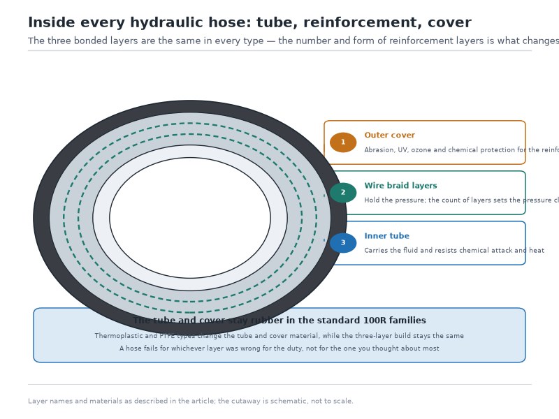
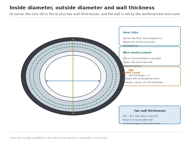
Every hydraulic hose in general hydraulic service is a three-layer composite, and each layer has one job and one characteristic failure mode. Understanding which layer does what is the fastest route to understanding why hose types differ.
Layer 1 — The Tube: Fluid Compatibility Before Pressure
The inner tube carries the fluid and must be chemically inert to it. In general hydraulic service it is a nitrile (NBR) compound, smooth-bored to keep flow restriction low. The tube is not the pressure-bearing layer, but it is the layer that decides whether the hose is legal for your fluid in the first place.
This is where most fluid mistakes happen. A standard NBR tube is excellent with mineral hydraulic oil, good with water-glycol (HFC) at reduced temperature, and unsuitable for phosphate ester (HFD-R) — which needs an EPDM or butyl tube instead. Diesel is limited to short-term use, and gasoline is not recommended at all in a standard hydraulic construction.
Experience note: in our own bench testing, the tube is also the layer that hides a problem the longest. A swelling or hardening NBR tube holds pressure perfectly well right up to the point where the cover blisters or the return-line filter starts loading with rubber crumbs. Chemical incompatibility almost never announces itself at the moment of installation.
Layer 2 — The Reinforcement: Braid or Spiral, and How Many
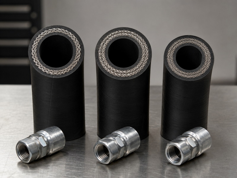
The reinforcement is the pressure-bearing element, and it is the single best predictor of what a hose can hold. Steel wire is laid over the tube in one of two geometries, and the geometry matters more than most buyers expect:
- Braided reinforcement interweaves the wire in a criss-cross pattern. It is more flexible at a given pressure, lighter, and cheaper per metre, which is why single and double braid dominate general hydraulic service.
- Spiralled reinforcement winds wire in one direction per layer, with successive layers laid in opposing directions. Spirals carry more wire per unit length, so they hold higher pressure, at the cost of stiffness and weight.
The wire is laid at a braid angle of approximately 54°44′. At that angle the reinforcement reaches neutral equilibrium under pressure: the hose neither elongates nor contracts significantly when pressurised. Depart from it and the hose will try to grow in length or pull itself shorter under load, which is why a kinked or twisted installation degrades a pressure rating even when nothing about the hose has changed.
Table 2. The three layers of a hydraulic hose, their materials, and what each one fails from
| Layer | Typical material | Function | Characteristic failure |
|---|---|---|---|
| Tube | Oil-resistant synthetic rubber (NBR), polyamide, or PTFE | Carries fluid; resists chemical attack and permeation | Swelling, hardening, cracking from an incompatible fluid or over-temperature |
| Reinforcement | One or more layers of high-tensile braided or spiralled steel wire; textile or polyester in lower-pressure types | Resists internal pressure and impulse cycling | Wire fatigue, corrosion of exposed wire, stress concentration after kinking |
| Cover | Abrasion-, weather-, ozone- and oil-resistant synthetic rubber, or an MSHA-listed compound | Protects the reinforcement from the environment and from contact with the machine | Cover cracking, blistering, and eventually abrasion through to bare wire |
Layer 3 — The Cover: AT, ST, and Why the Letters Matter
The cover is the layer you read the layline off, and its thickness is a variable you choose, not a constant. In SAE J517 designations, the letters after the 100R number describe the cover:
- AT — a thin, abrasion-resistant cover. Reduced outside diameter and weight, and more flexibility. This is the most common construction sold today; SAE 100R1AT and 100R2AT replaced the older A (non-removable cover) and B (removable cover) types.
- ST — a standard-thickness cover, offering more material for abrasion and physical protection where routing is rough and space is not tight.
- SC — the equivalent compact designation in the European EN 857 family (1SC and 2SC), which pairs a compact cover with a tighter minimum bend radius.
Both AT and ST hoses of the same family carry identical pressure ratings. The choice between them is about the environment the hose runs through, not about what it can hold — which is exactly why the layline has to distinguish them for you.
Experience note: when a customer reports that a boom hose failed “for no reason”, our first question is where it was touching steel. Cover type is not a pressure decision, but it is very often the reason a hose reached its date code without ever reaching its rating, or the reverse.
Hydraulic Hose Types: The Five Construction Families You Will Actually Meet
Hydraulic hose types are best sorted by reinforcement — reinforcement, not brand, is what sets the pressure ceiling. Five families cover the overwhelming majority of general hydraulic work, and they line up almost perfectly with a scale of increasing pressure capacity. The count depends on where the line is drawn: five pressure-ladder families (single braid, double braid, compact double braid, four-spiral and six-spiral), three specialist families (textile braid, thermoplastic and PTFE), and the wire-helix suction and return type. That is nine groups in total, which is why the same catalogue can be described as having five, six or nine — the count moves with the grouping, not with the hose. This section is the overview that sits above the specialist pages: the types of hydraulic hose construction comparison takes each family further, while the field-by-field layline decoding and the pressure rating definitions are covered here.
Single Wire Braid — SAE J517 100R1AT and EN 853 1SN
One braid of high-tensile steel wire over an oil-resistant tube. This is the workhorse for medium-pressure lines on mobile and stationary equipment, and the SAE 100R1 hydraulic hose is the construction most fleets standardise on.
Two naming notes before the numbers. First, throughout this guide R1 and R2 are hose construction designations — SAE 100R1 (one braid) and SAE 100R2 (two braids) — and they are unrelated to the R1 and R2 bend radius conventions used when measuring how tightly a hose is bent; our R1 versus R2 construction comparison covers the structural side of that question.
Second, two designations can describe the same construction and still publish different numbers. SAE 100R1AT, ISO 1436-1 1SN, EN 853 1SN and DIN 20022 1SN are nominally equivalent constructions, not identical published figures: the same 3/8 inch bore is published at 15.7 MPa (2,280 psi) on the SAE 100R1 table and 18 MPa (2,610 psi) on the EN 853 1SN table, because each figure belongs to the specification the hose was tested against. A hose built to one of those designations cannot be assumed interchangeable with another at the same dash size on pressure terms — check the figure for the standard your drawing calls up.
- Holds: 2,610 psi (18 MPa) at 3/8 inch on the EN 853 1SN table
- Good for: return lines, pilot lines, steering, medium-pressure work circuits, general industrial hydraulics
- Limits: pressure falls off quickly with bore — from 2,610 psi at 3/8 inch down to 580 psi (4 MPa) at 2 inch, on the same EN 853 1SN table
Double Wire Braid — SAE J517 100R2AT and EN 853 2SN
A second braid layer raises the working pressure by about 1.7 to 1.8 times in the common sizes on the SAE J517 tables — 15.7 MPa to 27.6 MPa at 3/8 inch, and 14 MPa to 24.1 MPa at 1/2 inch — and the step widens to about 2.4 times at 1-1/4 inch (4.3 MPa to 10.3 MPa). It is not a doubling, because the two braid layers do not carry identical loads. This is the default for main pressure lines on excavators, loaders, tractors, and most industrial hydraulics — see the SAE 100R2 hydraulic hose specification for the full size and pressure range. The same construction is published as SAE J517 100R2AT and as EN 853 2SN, and the two standards do not agree at every size, so every figure below is labelled with the standard it comes from. Our 100R1 vs 100R2 vs 100R16 by dash size comparison covers how the three constructions are chosen.
- Holds: 4,000 psi (27.6 MPa) at 3/8 inch and 3,500 psi (24.1 MPa) at 1/2 inch, on the SAE J517 100R2AT table
- Good for: boom and bucket cylinders, main pressure lines, high-cycle duty
- Limits: heavier than single braid at the same bore, and less flexible
Compact Double Braid — EN 857 2SC and SAE 100R16
A compact construction that delivers two-braid pressure in a smaller outside diameter, with a tighter bend radius. It is equivalent to SAE 100R16 and ISO 11237 2SC, and it exists because modern machines route hose through spaces that were never designed for the hose that was available when the machine was drawn.
- Holds: 4,785 psi (33 MPa) at 3/8 inch and 3,990 psi (27.5 MPa) at 1/2 inch, on the EN 857 2SC table
- Good for: tight routing, crowded manifolds, size- and weight-limited mobile equipment
- Limits: less cover material to give away to abrasion
Four- and Six-Spiral — SAE 100R12, SAE 100R13, EN 856 4SP and 4SH
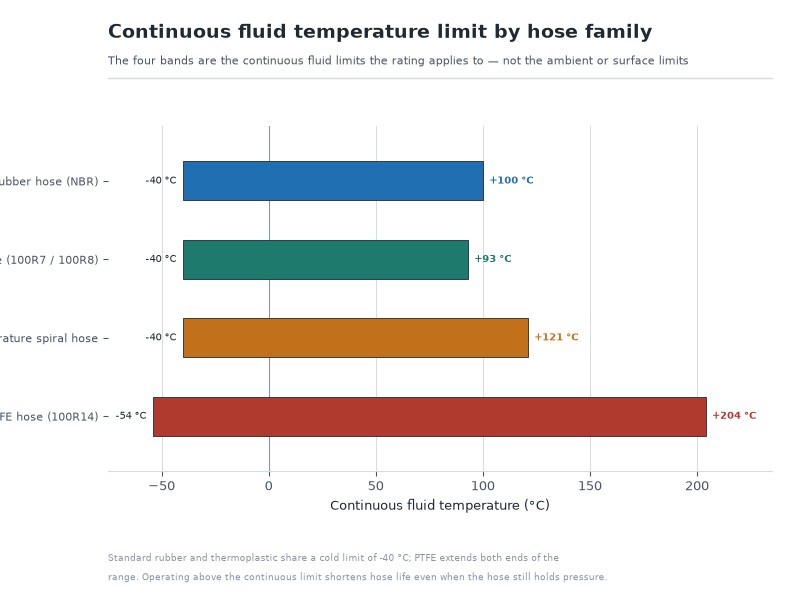
Spiral construction is where hydraulic hose becomes genuinely high pressure. Four spirals (SAE 100R12, EN 856 4SP) cover the 4,000–5,000 psi band; six spirals (SAE 100R13, EN 856 4SH) go beyond it. Both run hotter than braided hose: the standard temperature window for these families is −40°C to +121°C.
The most useful property of a six-spiral hose is that its rating does not decay with size. SAE 100R12 falls from 4,060 psi at 1 inch to 2,540 psi at 2 inch. SAE 100R13 holds 5,075 psi (35 MPa) across every size from 3/4 inch to 2 inch. For a large-bore high-pressure circuit, that flat curve is often the reason SAE 100R13 is specified at all.
Minimum bend radius is the counterweight to that flat curve: it runs from 125 mm at 3/8 inch to 640 mm at 2 inch on SAE 100R12, and from 240 mm at 3/4 inch to 640 mm at 2 inch on SAE 100R13. Spiral hose holds its pressure across the size range, and pays for it in routing space.
- Holds: 5,075 psi (35 MPa) constant on SAE 100R13 from 3/4 inch to 2 inch, and SAE 100R12 falls from 4,060 psi at 1 inch to 2,540 psi at 2 inch
- Good for: heavy-duty boom and implement circuits, mining and drilling equipment, press and injection-moulding hydraulics
- Limits: stiff, heavy (up to 7.0 kg/m at 2 inch in SAE 100R13), and more expensive per metre
Textile, Thermoplastic, and PTFE
Three specialist families sit outside the main pressure ladder:
- Textile braid (SAE 100R3, 100R6) — fibre reinforcement in place of wire, for low-pressure return and general lines where flexibility and cost matter more than pressure.
- Thermoplastic (SAE 100R7, 100R8) — a polymer core with fibre or wire reinforcement, used where electrical isolation matters. Non-conductive 100R7, 100R8 and 100R18 thermoplastic hose is commonly finished with an orange cover, but the colour is a convention rather than a requirement, so confirm non-conductivity from the marking rather than from the colour.
- PTFE (SAE 100R14) — a PTFE core with a stainless steel braid, for extreme temperature and aggressive chemistry. Type A and Type B designations apply within this family.
Suction and Return — SAE 100R4
Return and suction lines run at low pressure but are the only family that must resist collapse rather than burst. SAE 100R4 adds a wire helix to hold the bore open under vacuum, which is why it is the one family specified by collapse resistance rather than by burst pressure. Specify SAE 100R4 for any line that has to hold suction, and the wire helix inside the wall confirms it.
- Holds: vacuum rather than pressure — the helix keeps the bore open under collapse loading, so the figure that matters is collapse resistance, not working pressure
- Limits: the helix adds weight and stiffness, so a suction hose is the heavier choice wherever a plain return line would do
Table 3. Hydraulic hose types compared by reinforcement, published working pressure at 1/2 inch bore, flexibility, temperature window, and typical duty. The figure shown is the published value of the designation that publishes one for that size, and each row is labelled with the standard it is published against; a dash means no 1/2 inch rating is published for that family.
| Family | Reinforcement | Working pressure at 1/2 inch | Relative flexibility | Temperature window | Typical duty |
|---|---|---|---|---|---|
| SAE J517 100R1AT | One braid of steel wire | 2,030 psi (14 MPa) | High | −40°C to +100°C | Return, pilot, steering, medium-pressure work lines |
| EN 853 1SN | One braid of steel wire (equivalent construction) | 2,320 psi (16 MPa) | High | −40°C to +100°C | Same duty as SAE 100R1, separate published figures |
| SAE J517 100R2AT | Two braids of steel wire | 3,500 psi (24.1 MPa) | Medium-high | −40°C to +100°C | Main pressure lines, boom and bucket cylinders |
| EN 853 2SN | Two braids of steel wire (equivalent construction) | 3,500 psi (24.0 MPa) | Medium-high | −40°C to +100°C | Same duty as SAE J517 100R2AT, separate published figures |
| EN 857 2SC / SAE 100R16 | Two compact braids | 3,990 psi (27.5 MPa) | High (tight bend radius) | −40°C to +100°C | Constrained routing, crowded manifolds |
| SAE 100R12 / EN 856 4SP | Four spiralled steel wire layers | 4,060 psi (28 MPa) | Low | −40°C to +121°C | Heavy-duty high-pressure circuits |
| SAE 100R13 (published from −12, 3/4 inch) | Six spiralled steel wire layers | — | Low | −40°C to +121°C | Ultra-high-pressure, large bore, mining and drilling |
| SAE 100R3 / 100R6 | Textile braid | Not published in this table | Very high | −40°C to +100°C | Low-pressure return and general lines |
| SAE 100R7 / 100R8 / 100R18 | Thermoplastic core with fibre or wire reinforcement | Not published in this table | High | −40°C to +93°C | Non-conductive service (orange cover), compact machinery |
| SAE 100R14 | PTFE core, stainless steel braid | Not published in this table | Medium | −54°C to +204°C | Aggressive chemistry, extreme temperature |
| SAE 100R4 | Textile or wire with wire helix | Not published in this table (vacuum-rated) | Medium | −40°C to +100°C | Return lines and suction lines subject to collapse |
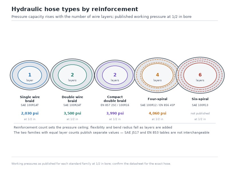
Figure 1. Hydraulic hose types arranged by reinforcement, from a single braid up to six spirals. Pressure capacity rises with the number of wire layers; flexibility and bend radius fall.
How to Read a Hydraulic Hose Layline, Field by Field
The layline is read in a fixed field order — manufacturer, standard and type, dash size, working pressure, temperature, date code — and each field decides one thing about the replacement. It is a mechanical exercise once you know that order. The string is printed repeatedly along the hose, so you can read a complete copy at almost any point along the cover. Work through the fields in the order below.
Field 1 — Manufacturer Name or Trademark
This is the first field and the one that determines what every other field means. The manufacturer’s name or trademark is required on the layline precisely because the pressure figures printed next to it belong to *that* manufacturer’s specification for *that* hose. A working pressure on a layline is a manufacturer’s declaration against a standard, not a universal law of physics.
Practical consequence: two hoses that both read “100R2AT -08” from two different factories may print slightly different working pressures, and both can be correct. Their internal pressure test data, compound choice, and tolerances differ. This is not a defect. It is why you should confirm the rating from the supplier’s own spec sheet rather than a general pressure chart found elsewhere.
Field 2 — The Standard and Type Code
This is the densest field and the most useful. Take `SAE 100R2AT-08` as an example and unpack it in three parts:
Table 4. Decoding a designation: what each part of SAE 100R2AT-08 means
| Element | Meaning |
|---|---|
100R2 | The SAE J517 hose type. R2 = double wire braid |
AT | Cover type: thin, abrasion-resistant. ST would mean a standard-thickness cover |
-08 | Dash size: nominal bore in sixteenths of an inch, so 8/16 = 1/2 inch |
The same physical hose sold under the European system would read `EN 853 2SN`, and under ISO, `ISO 1436 2SN`. Recognising the equivalences is what stops you from rejecting a perfectly interchangeable hose because the letters on the cover are unfamiliar:
Table 5. Cross-reference of the equivalent hydraulic hose designations you will meet on a layline
| Construction | SAE designation | EN designation | ISO designation |
|---|---|---|---|
| Single wire braid | SAE 100R1AT | EN 853 1SN | ISO 1436-1 1SN |
| Double wire braid | SAE 100R2AT | EN 853 2SN | ISO 1436-1 2SN |
| Compact double braid | SAE 100R16 | EN 857 2SC | ISO 11237 2SC |
| Four spiral | SAE 100R12 | EN 856 4SP | ISO 3862 R12 |
| Six spiral | SAE 100R13 | EN 856 4SH | ISO 3862 R13 |
| Suction and return | SAE 100R4 | — | ISO 6807 |
| Thermoplastic | SAE 100R7 / 100R8 | — | ISO 3949 |
| PTFE | SAE 100R14 | — | — |
If you work across both systems regularly, keep a cross-reference to hand rather than converting pressure figures from memory, and record the designation the drawing calls up rather than the one that happens to be on the shelf. The cross-reference table above is that reference: read across the row, not down a pressure chart.
Field 3 — Dash Size and Nominal Bore
The hydraulic hose dash size is the nominal bore in sixteenths of an inch. It is a *nominal* figure: an −08 hose is a 1/2 inch hose, but the actual inside diameter has a tolerance band, typically 12.3 mm to 13.5 mm on general hydraulic hose. Dash size is what fittings, crimp dies, and the machine’s design drawings are keyed to, so it is the field to record first when ordering a replacement. Our dash size to bore conversion chart carries the full dash-to-millimetre table, and the minimum bend radius by dash size figures sit on the same basis — a −08 hose has a 180 mm minimum bend radius.
Field 4 — Working Pressure in psi and MPa
Most general hydraulic hose prints working pressure in both units, for example `24.1 MPa / 3500 psi`. Where two figures appear, they are the same pressure expressed twice, not two different ratings — 24.1 MPa converts to approximately 3,500 psi.
Read this field carefully for three things:
- Unit confusion. Treating a metric figure as imperial (or the reverse) is a common and expensive error when a hose is being sourced across a metric/imperial boundary. If the two figures appear not to agree, re-check the conversion factor (1 MPa = 145.04 psi) before assuming a misprint.
- The rating belongs to the size. A working pressure figure is only valid for the dash size printed on the same line.
- It is a working pressure, not a burst pressure. The layline normally prints the working pressure only. The burst pressure lives on the spec sheet.
Field 5 — Temperature Range
Where a temperature window is printed, it defines the conditions under which the pressure rating is valid. General hydraulic rubber hose is commonly rated −40°C to +100°C, while four- and six-spiral constructions run to +121°C. Exceed either end and the printed pressure figure no longer applies, even though the number on the cover has not changed. Water-glycol fluids, for example, typically require a derated pressure and a lower temperature ceiling than mineral oil in the same hose.
Field 6 — The Date Code: Quarter and Year of Manufacture
This is the field most often misread and the one with the most direct commercial consequence. Under SAE J517, the date of manufacture may be expressed as month, day, and year (2/19/88), as month and year (2/88), or as quarter and year (1Q88), at the manufacturer’s option. Date of manufacture is optional on SAE 100R7, 100R8, and 100R18.
`3Q26` therefore means the third quarter of 2026 — not March 2026. Reading a quarter code as a month is a routine error, and it shifts the age of the hose by up to nine months. The date code is the anchor for every shelf-life and replacement decision you make afterwards, so record it as a two-part value: quarter number and year.
Field 7 — Special Markings
Beyond the core fields, some laylines carry approvals that change how the hose may be used:
- MSHA listing — required for certain underground mining service, where flame resistance is a separate qualification from pressure
- Non-conductive marking — on thermoplastic hose intended for electrically isolated service, and correlated with the orange cover reserved for 100R7, 100R8, and 100R18
- Marine approvals — type approvals such as DNV or ABS for deck machinery and marine systems
- Standard equivalence statements — where a manufacturer prints the ISO or EN equivalent alongside the SAE designation
What a Hydraulic Hose Layline Does Not Tell You
A layline is a summary, not a data sheet. It does not tell you:
- Burst pressure — read it from the spec sheet, where the standards set it at four times the maximum working pressure, or calculate it from the working pressure at that same 4 × relation
- The minimum bend radius for that specific bore
- Crimp dimensions or fitting compatibility for the assembly
- Whether the hose has been damaged since manufacture — that is an inspection task, not a reading task
- Whether it is genuine. A layline is a declaration. Verification means buying from a source that can produce test records.
Table 6. Layline field, what you do with it, and the mistake it prevents
| Field | Action it enables | Mistake it prevents |
|---|---|---|
| Manufacturer | Go to the correct spec sheet and test record | Applying another factory’s pressure chart to this hose |
| Standard and type | Confirm construction and find the equivalent in EN or ISO terms | Rejecting an interchangeable hose; accepting a lower-spec substitute |
| Dash size | Order the right hose and the right fittings and dies | Fitting an assembly that will not seal or will not flow |
| Working pressure | Compare against the system’s relief valve setting | Designing to a burst figure or to a metric/imperial mix-up |
| Temperature range | Confirm the fluid and ambient window | Using a rating that expired at a temperature you are running above |
| Date code | Start the shelf-life and replacement clock | Putting a decade-old hose back into high-cycle service |
| Special approvals | Confirm the hose is admissible for the application | Failing an inspection or an audit on a compliance technicality |
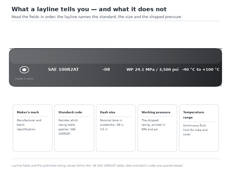
Figure 2. The parts of a layline: manufacturer, standard and type code, dash size, working pressure, temperature range, and date code. The string repeats along the full length of the cover.
Why Is There a Layline on a Hydraulic Hose?
The question reaches us in two forms — why the cover carries a printed line at all, and how to identify a hose once that print has worn away — and both answers start in the same place. A hydraulic hose is a safety-critical component that becomes anonymous the moment it leaves the factory, and marking is a requirement rather than a marketing choice. Four forces put the printing there.
Traceability. A hose that fails in service can be traced back to a production lot, a test record, and a date of cure. Without a printed identifier, an assembly that burst on a mining machine is an unattributable piece of rubber, and no one can determine whether the cause was manufacturing, installation, or application.
Reorder accuracy. A technician replacing a hose on a machine in the field has one reliable source of truth: the hose that is already there. The layline is designed so that the same string can be quoted directly to a supplier, which is the purpose it serves in most daily use.
Standard compliance. Marking is a requirement of the standards themselves, not a marketing choice. SAE J517 specifies which fields must appear and in what sequence; EN 853 and ISO 1436 specify equivalent marking requirements for their own designations. A hose that cannot be identified cannot be demonstrated to conform.
Counterfeit and substitution detection. A layline that is missing, incomplete, or inconsistent with the hose’s physical construction is a strong signal that the product is not what it claims to be. Where a hose carries a braid count, a bore, and a pressure that do not agree with each other, that mismatch is detectable at the bench before the hose is installed.
Experience note: a hose that carries a proof record can be traced from the printed date code back to its test data, which is why the date code is the field to log at installation. When a rating is queried two years after delivery, the quarter code is usually what identifies which lot the hose belongs to. That is the practical value of a field that looks like decoration until the day it matters.
Worked Example: Decoding a Layline in Five Steps
Every layline carries the same fields in the same order, so the worked example below is a sequence you can copy. The figures are illustrative of the format; the field order is the part worth memorising.
“` HENGHUA SAE 100R2AT -08 1/2 WP 24.1 MPa 3500 psi -40°C to +100°C 3Q26 “`
Step 1 — Identify the maker and the standard. `HENGHUA` plus `SAE 100R2AT` tells you this is a double wire braid hose with a thin abrasion-resistant cover, built to SAE J517. The `AT` matters: it is a thin-cover variant, so the outside diameter is smaller than a standard-cover hose at the same bore.
Step 2 — Read the size. `-08` and `1/2` agree with each other: 8 sixteenths of an inch is 1/2 inch. When the dash size and the fractional size disagree, stop. A mismatch means either a misprint or a substituted product.
Step 3 — Read the pressure and check the units agree. `24.1 MPa` and `3500 psi` are the same rating. Confirm the pair converts (24.1 × 145.04 ≈ 3,496, which rounds to the published 3,500 psi), then compare the figure against the system’s relief valve setting, not against an estimated working pressure.
Step 4 — Read the temperature window. `-40°C to +100°C`. If the machine runs water-glycol fluid or sits in a high-ambient environment, this is the field that decides whether the pressure rating above is still valid.
Step 5 — Record the date code. `3Q26` — third quarter of 2026. Log it against the machine, not against the purchase order. The date code belongs to the hose, and it is the number that will still be readable in five years when the paperwork is gone.
Table 7. Worked layline decoding, field by field
| Token on the layline | Field | Decoded value | Action |
|---|---|---|---|
| HENGHUA | Manufacturer | HENGHUA | Reference that factory’s spec sheet and test record |
| SAE 100R2AT | Standard and type | Double wire braid, thin abrasion-resistant cover (SAE J517) | Look up the R2AT specification for the dash size |
| -08 / 1/2 | Size | Nominal bore 8/16 inch = 12.5 mm nominal | Order matching -08 fittings and crimp die |
| WP 24.1 MPa 3500 psi | Working pressure | 24.1 MPa (≈3,500 psi) maximum continuous | Compare against the relief valve setting with an allowance for surge |
| -40°C to +100°C | Temperature range | Rating valid across this window only | Check fluid type and ambient extremes |
| 3Q26 | Date of manufacture | Third quarter of 2026 | Start the shelf-life and replacement clock |
What Do Hydraulic Hose Markings, Tags and Labels Tell You?
Hydraulic hose markings are not one practice but three, and the differences decide what will still be readable after two years of service.
- Layline printing (permanent). Characters are printed directly onto the cover during manufacture and repeat along the length. This is the only marking method that is genuinely permanent and the only one that survives cover abrasion in the areas that matter.
- Wrap or sleeve labels. A printed band applied over the hose. Useful for assembly identification, and useful in the warehouse — but a wrap can be abraded, peeled, or cut away.
- Metal or plastic tags. Attached with a wire or tie, often carrying test data or an assembly number. Tags survive heat and chemicals well, but they are attached rather than integral, and they are the first thing lost on a machine that moves.
The practical rule: treat the layline as the permanent record and treat tags as convenience. If you need a hose identified in five years, the answer has to be printed on the cover.
How to Identify a Hose When the Layline Has Worn Off
Hydraulic hose markings do wear away, most often exactly where the hose was chafing. When it is gone, work through these six checks in order:
- Measure the bore. Use calipers on the inside diameter, then convert it to the nearest hydraulic hose dash size. For a 1/2 inch hose, expect roughly 12.3 to 13.5 mm.
- Measure the outside diameter. The OD separates a standard-cover hose from a compact or thin-cover one at the same bore.
- Count the visible reinforcement. Cut a scrap length and count wire layers. One braid = R1 class; two braids = R2 or R16 class; four or six opposing spiral layers = R12 or R13 class.
- Check the flexibility and bend radius. A hose that resists bending into the radius the machine needs is probably a spiral, not a braid.
- Check for a helix. A wire helix visible inside or implied by the hose resisting vacuum collapse indicates a suction and return construction.
- Match the fittings. The fitting series already crimped on the assembly narrows the possible constructions, and it has to be reproduced regardless of what the hose was.
Hydraulic Hose Pressure Ratings: Working, Proof, and Burst Pressure
A hydraulic hose pressure rating is not one number. It is a set of three — working, proof and burst — and the relationship between them is fixed by the standard. Our working pressure vs burst pressure explainer takes the same three figures apart size by size.
Table 8. The three figures behind a hydraulic hose pressure rating, and what each one permits
| Figure | Definition | Typical relationship | What it means in practice |
|---|---|---|---|
| Working pressure (WP) | The maximum continuous pressure the hose is rated to operate at | Baseline figure, printed on the layline | Design to this figure, with margin above the relief valve setting. Never exceed it in continuous service |
| Proof pressure | A test pressure applied to every hose or assembly before shipment | Typically 2× working pressure, as published on the EN 853 1SN and EN 857 2SC tables | A quality gate, not an operating limit. Passing it proves integrity, not headroom |
| Minimum burst pressure | The pressure at which the hose construction is expected to rupture | Minimum burst pressure = 4 × maximum working pressure (EN 853 / EN 857 / SAE J517) | A standard requirement, not a target and not an operating allowance |
What “Four Times Working Pressure” Actually Means
The minimum burst figure in Table 8 is a standard requirement, not an operating allowance, and it is the figure in a hydraulic hose pressure rating that gets misread more than any other. The trade often calls this a “4:1 safety factor”, but the standards define it as a minimum burst pressure of four times the maximum working pressure (EN 853, EN 857 and SAE J517) — a burst relation, not reserve pressure you may use. It exists to absorb four specific things:
- Pressure spikes. A relief valve does not prevent the transient peaks that occur when a valve closes against moving fluid. The burst requirement is what keeps those spikes from being fatigue events.
- Impulse cycling. Under impulse testing to EN ISO 6803, a hose is cycled at 133% of its working pressure at 100°C, for a minimum of 200,000 cycles. The four-times minimum burst requirement is what allows a hose to survive hundreds of thousands of those pressure reversals before wire fatigue begins.
- Temperature excursions. A rating is valid inside the printed temperature window. At the top of that window, fluid and compound degradation accelerates.
- Age and installation quality. A hose that has been in service for years, or that was installed with a twist, is no longer performing at its original rating.
The correct design practice is to size the hose so the working pressure exceeds the relief valve setting with an allowance for surge, then confirm the temperature and fluid are inside the printed window. Designing to the burst figure removes every one of these protections.
Safety note: never run a hand along a pressurised hose to trace a leak. Use cardboard or detection dye, and treat any fluid-injection injury as a surgical emergency — hydraulic fluid forced under the skin is a medical emergency, not a cut. It is the one rule in this section that has nothing to do with the numbers printed on the cover.
Does a Hydraulic Hose Pressure Rating Drop as Hose Size Increases?
For braided hose, yes — and sharply. Bore area rises with the square of the diameter — a 1 inch bore carries sixteen times the area of a 1/4 inch bore (π/4 × 1² ÷ (π/4 × 0.25²) = 16) — so hoop stress at a given pressure rises with the bore, and a single braid layer cannot hold the same rating as the size grows. The same area ratio works the other way for flow: the larger bore moves the same volume at a much lower velocity, which is why a big bore is chosen for return lines where pressure drop and heat matter. Pressure capacity is set by hoop stress, and that is what falls. A single-braid hose loses about 88 percent of its working pressure between 3/16 inch and 2 inch on the SAE 100R1 table — 3,045 psi down to 380 psi — and about 84 percent on the EN 853 1SN table, where the same span runs from 3,625 psi to 580 psi.
For spiral hose, it depends on the family. Four-spiral SAE 100R12 holds a flat 28 MPa from 3/8 inch through 1 inch and only then falls. Six-spiral SAE 100R13 maintains a constant 35 MPa across every size from 3/4 inch to 2 inch.
Table 9. Published working pressure by hose type and size, in MPa. Bracketed values are the equivalent psi figure. The dash indicates the size is not published for that family. Each row is published against the standard named in that row.
| Hose type | −6 (3/8″) | −8 (1/2″) | −12 (3/4″) | −16 (1″) | −20 (1¼″) | −32 (2″) |
|---|---|---|---|---|---|---|
| SAE J517 100R1AT (1 braid) | 15.7 (2,280) | 14 (2,030) | 8.7 (1,260) | 7 (1,015) | 4.3 (620) | 2.6 (380) |
| SAE J517 100R2AT (2 braids) | 27.6 (4,000) | 24.1 (3,500) | 17.2 (2,500) | 13.8 (2,000) | 10.3 (1,500) | 6.9 (1,000) |
| EN 853 2SN (2 braids) | 27.5 (4,000) | 24 (3,500) | 19 (2,750) | 15.5 (2,250) | 11.2 (1,625) | 8.6 (1,250) |
| EN 853 1SN | 18 (2,610) | 16 (2,320) | 10.5 (1,520) | 8.8 (1,280) | 6.3 (910) | 4 (580) |
| EN 857 2SC (compact) | 33 (4,785) | 27.5 (3,990) | 21.5 (3,120) | 16.5 (2,390) | — | — |
| SAE 100R12 (4 spiral) | 28 (4,060) | 28 (4,060) | 28 (4,060) | 28 (4,060) | 21 (3,045) | 17.5 (2,540) |
| SAE 100R13 (6 spiral) | — | — | 35 (5,075) | 35 (5,075) | 35 (5,075) | 35 (5,075) |
One point about that table deserves to be stated plainly, because it is the clearest argument for reading the layline rather than a chart: SAE 100R1 and EN 853 1SN are nominally equivalent constructions, but the published working pressures differ — 15.7 MPa against 18 MPa at 3/8 inch, from the same factory. Both figures are published against their own specification and both are correct for the hose they describe. If you substitute one for the other on the basis of a generic conversion chart, you have chosen a rating rather than read one. Where two pages of the same catalogue publish different figures for the same 3/8 inch size, treat the datasheet of the hose you are holding as the authority and ask the manufacturer to reconcile the two. The two-line-braid pair behaves the same way: SAE J517 100R2AT and EN 853 2SN publish the same working pressure through 1/2 inch and diverge from 3/4 inch upward, so the standard named on the layline decides which figure applies to the hose in your hand.
Pressure Rating Tables by Size
SAE 100R1 and SAE 100R2 are the two families most general hydraulic work uses, and their published figures sit in a fixed ratio at every size: proof pressure is twice the working pressure, and minimum burst pressure is four times it. Proof pressure is the test every production length is subjected to; minimum burst pressure is the lowest pressure at which rupture is expected. Both relations are named in the standards these tables are published against — the requirement that minimum burst pressure be four times the maximum working pressure is stated in EN 853 1SN and EN 857 2SC, and applies across the SAE J517 designations.
Table 10. SAE J517 100R1AT single wire braid — published working, proof, and minimum burst pressure by size. Basis: the manufacturer’s published specification table for this designation; the equivalent EN 853 1SN table publishes different figures at some sizes.
| Dash size | Inch size | ID (mm) | Working pressure (MPa / psi) | Proof pressure (MPa / psi) | Minimum burst pressure, 4 × WP (MPa / psi) | Min bend radius (mm) |
|---|---|---|---|---|---|---|
| −3 | 3/16 | 4.6 – 5.4 | 21 / 3,045 | 42 / 6,090 | 84 / 12,810 | 90 |
| −4 | 1/4 | 6.2 – 7.0 | 19.2 / 2,780 | 38.5 / 5,580 | 77 / 11,165 | 100 |
| −5 | 5/16 | 7.7 – 8.5 | 17.5 / 2,540 | 35 / 5,075 | 70 / 10,150 | 115 |
| −6 | 3/8 | 9.3 – 10.1 | 15.7 / 2,280 | 31.5 / 4,570 | 63 / 9,135 | 125 |
| −8 | 1/2 | 12.3 – 13.5 | 14 / 2,030 | 28 / 4,060 | 56 / 8,120 | 180 |
| −10 | 5/8 | 15.5 – 16.7 | 10.5 / 1,520 | 21 / 3,045 | 42 / 6,090 | 205 |
| −12 | 3/4 | 18.6 – 19.8 | 8.7 / 1,260 | 17.5 / 2,540 | 35 / 5,075 | 240 |
| −16 | 1 | 25.0 – 26.4 | 7 / 1,015 | 14 / 2,030 | 28 / 4,060 | 300 |
| −20 | 1-1/4 | 31.4 – 33.0 | 4.3 / 620 | 8.7 / 1,260 | 17.5 / 2,540 | 420 |
| −24 | 1-1/2 | 37.7 – 39.3 | 3.5 / 510 | 7 / 1,015 | 14 / 2,030 | 500 |
| −32 | 2 | 50.4 – 52.0 | 2.6 / 380 | 5.2 / 750 | 10.5 / 1,520 | 630 |
Table 11. SAE J517 100R2AT double wire braid — published working pressure by size, with proof pressure and minimum burst pressure shown at the relations the standard sets (2 × WP and 4 × WP). The equivalent EN 853 2SN table publishes different figures from 3/4 inch upward, as Table 9 shows. A dash means the designation is not published at that size. Inside-diameter tolerance and minimum bend radius are the published dimensions for the same dash size.
| Dash size | Inch size | ID (mm) | Working pressure (MPa / psi) | Proof pressure (MPa / psi) | Minimum burst pressure, 4 × WP (MPa / psi) | Min bend radius (mm) |
|---|---|---|---|---|---|---|
| −3 | 3/16 | 4.6 – 5.4 | — | — | — | — |
| −4 | 1/4 | 6.2 – 7.0 | 34.5 / 5,000 | 69 / 10,000 | 138 / 20,000 | 100 |
| −5 | 5/16 | 7.7 – 8.5 | — | — | — | — |
| −6 | 3/8 | 9.3 – 10.1 | 27.6 / 4,000 | 55.2 / 8,000 | 110.4 / 16,000 | 125 |
| −8 | 1/2 | 12.3 – 13.5 | 24.1 / 3,500 | 48.2 / 7,000 | 96.4 / 14,000 | 180 |
| −10 | 5/8 | 15.5 – 16.7 | 20.7 / 3,000 | 41.4 / 6,000 | 82.8 / 12,000 | 205 |
| −12 | 3/4 | 18.6 – 19.8 | 17.2 / 2,500 | 34.4 / 5,000 | 68.8 / 10,000 | 240 |
| −16 | 1 | 25.0 – 26.4 | 13.8 / 2,000 | 27.6 / 4,000 | 55.2 / 8,000 | 300 |
| −20 | 1-1/4 | 31.4 – 33.0 | 10.3 / 1,500 | 20.6 / 3,000 | 41.2 / 6,000 | 420 |
| −24 | 1-1/2 | 37.7 – 39.3 | 8.6 / 1,250 | 17.2 / 2,500 | 34.4 / 5,000 | 500 |
| −32 | 2 | 50.4 – 52.0 | 6.9 / 1,000 | 13.8 / 2,000 | 27.6 / 4,000 | 630 |
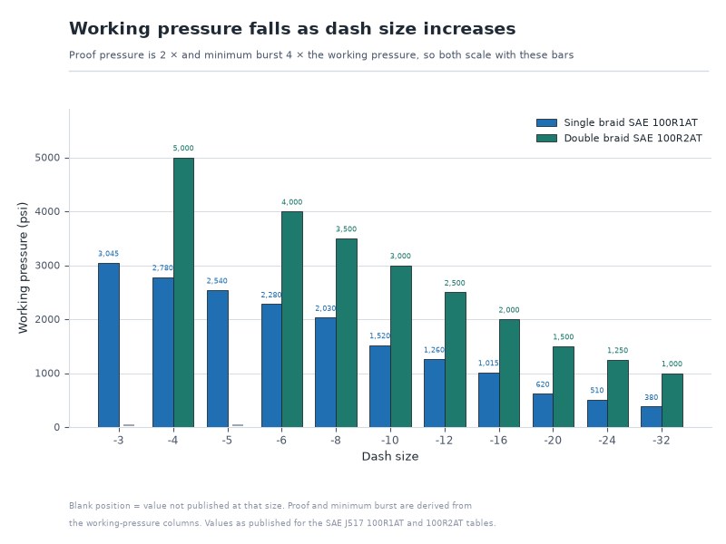
Figure 3. Working, proof, and burst pressure fall as bore rises on braided hose. Proof pressure is twice the working pressure and minimum burst pressure is four times it, at every size.
Hydraulic Hose Size Chart: How Do You Convert Dash Size to Bore and Flow?
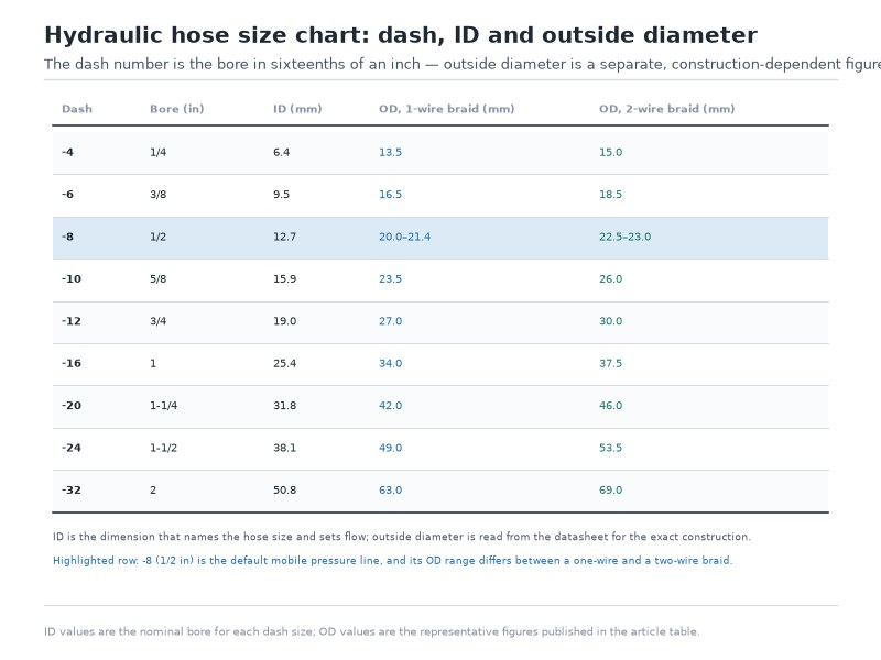
A hydraulic hose size chart is the bridge between the four ways the same hose size is written, and it is the shared language between the hose, the fittings, the crimp die, and the machine drawing. The table below converts dash size to inch and metric bore, and adds the minimum bend radius and an indicative flow figure. The hydraulic hose dash size is the single value that connects all four.
Table 12. Hydraulic hose dash size converted to inch and metric bore, with ID tolerance, published minimum bend radius (SAE 100R1 / SAE J517 100R2AT basis; other families publish different radii), and calculated flow at 20 ft/s. The nominal column is the commercial call-out used in catalogues and on drawings; the tolerance column is the manufactured range. Flow uses the exact inch bore, not the nominal column: Q (gpm) = V (ft/s) × A (in²) × 3.117, where A is π/4 × ID², equivalently v = 0.4085 × Q ÷ d². Flow figures are rounded to one decimal place.
| Dash size | Inch size | Nominal bore (mm, commercial call-out) | ID tolerance (mm) | Min bend radius (mm) | Flow at 20 ft/s (gpm) |
|---|---|---|---|---|---|
| −3 | 3/16 | 5 | 4.6 – 5.4 | 90 | 1.7 |
| −4 | 1/4 | 6.3 | 6.2 – 7.0 | 100 | 3.1 |
| −5 | 5/16 | 8 | 7.7 – 8.5 | 115 | 4.8 |
| −6 | 3/8 | 10 | 9.3 – 10.1 | 125 | 6.9 |
| −8 | 1/2 | 12.5 | 12.3 – 13.5 | 180 | 12.2 |
| −10 | 5/8 | 16 | 15.5 – 16.7 | 205 | 19.1 |
| −12 | 3/4 | 19 | 18.6 – 19.8 | 240 | 27.5 |
| −16 | 1 | 25 | 25.0 – 26.4 | 300 | 49.0 |
| −20 | 1-1/4 | 31.5 | 31.4 – 33.0 | 420 | 76.5 |
| −24 | 1-1/2 | 38 | 37.7 – 39.3 | 500 | 110.2 |
| −32 | 2 | 51 | 50.4 – 52.0 | 630 | 195.8 |
The flow figures are a sizing guide, not a specification, and they are reproducible: Q (gpm) = V (ft/s) × A (in²) × 3.117, where A is π/4 × ID² — equivalently v = 0.4085 × Q ÷ d². They assume the exact nominal bore of each dash size — 12.7 mm for a −08 (1/2 inch) hose, rather than the rounded 12.5 mm shown in the bore column — at a target fluid velocity of 20 ft/s, and are rounded to one decimal place. Real pressure drop also depends on fluid viscosity, temperature and hose length. Velocity is a choice, not a constant: lower velocities reduce pressure drop and heat generation but require a larger, heavier hose. On suction lines the constraint reverses entirely, and the hose is selected for vacuum collapse resistance before flow is considered at all.
Replacing a hose from a worn layline? Send us the string you can still read, the bore and length you measured, and a photo of the fitting at each end — our engineers will confirm the construction and the rating before anything is crimped.
How Long Is a Hydraulic Hose Good For? Date Codes and Shelf Life
The date code on a layline is not a manufacturing curiosity. It is the starting point of two different clocks, and they run at different speeds.
Storage clock (unused hose). An unused hose in a dark, dry store degrades slowly. The serviceable storage expectation for rubber hydraulic hose is commonly measured in years, not months, and it shortens sharply with UV exposure, ozone, heat, and humidity. Because the date code is printed at cure, you can verify the age of a “new” hose on delivery — which is its own reason to read the layline before accepting a shipment.
Service clock (installed hose). In service, life is governed by impulse cycles, temperature, and routing rather than by calendar age. A hose on a high-cycle pressure line at the top of its temperature window can reach end of life in a fraction of the time a low-pressure return line takes.
Replacement Triggers You Can Actually Observe
Replace rather than inspect when you find any of the following:
- Exposed or corroded wire reinforcement — the pressure-bearing layer is already compromised
- Cover cracks that reach the reinforcement, or blistering and soft spots that indicate tube degradation
- Fitting movement, weeping, or a pulled ferrule — the assembly, not the hose, has failed
- A kinked section, which has permanently damaged the braid angle at that point
- Any hose that has been in high-cycle service for an extended period, regardless of appearance
Experience note: our strongest recommendation to maintenance teams is to log the date code at installation rather than at purchase. It costs one field on a spreadsheet and it converts “this hose looks fine” into a defensible replacement decision — which is what an auditor or an insurer will ask for after a failure.
Five Mistakes That Make a Layline Useless
Reading a hydraulic hose layline correctly is easy. These five errors happen after the reading, and each one discards the information the layline just gave you.
1. Designing to the burst pressure. The four-times burst requirement is a design rule against spikes and fatigue, not a licence to run a hose at four times its rating. If a system’s relief valve is set above the printed working pressure, the hose is undersized regardless of what the burst figure says. Most burst failures trace back to a known, inspectable cause — a cover that has reached the wire, a kink, a pulled ferrule — rather than to a manufacturing defect in a hose that was correctly specified.
2. Ignoring the temperature field. A hydraulic hose pressure rating is conditional on the temperature window. Run above it and the printed figure is stale, even though it is still perfectly legible.
3. Mixing units. `24.1 MPa` and `3500 psi` describe the same hose. Treating the metric figure as a different scale is a routine and costly error when sourcing across metric and imperial markets.
4. Reading the quarter code as a month. `3Q26` is the third quarter of 2026, not March. Every shelf-life and warranty calculation downstream inherits that mistake.
5. Substituting on a generic chart. Two hoses can carry the same designation and different tested ratings, as the SAE 100R1 and EN 853 1SN figures above demonstrate. The layline names the manufacturer for a reason.
Applications: Which Type Goes Where
Choosing a construction is easier once the hydraulic hose basics are settled: the reinforcement sets the pressure ceiling, and the application sets the construction. Confirm the bore and the minimum bend radius from the dash size on the hydraulic hose size chart before ordering — a −08 hose is 1/2 inch nominal bore, 12.3 to 13.5 mm inside, with a 180 mm minimum bend radius.
Table 13. Hydraulic hose types mapped to typical applications and the constraint that decides the choice
| Application | Common construction | Deciding constraint |
|---|---|---|
| Excavator boom and bucket cylinders | Double braid (SAE J517 100R2AT / EN 853 2SN) | Pressure plus constant flexing and abrasion against the boom |
| Excavator pilot and return lines | Single braid (SAE J517 100R1AT / EN 853 1SN) | Lower pressure, high flexibility, low cost |
| Constrained routing and crowded manifolds | Compact double braid (EN 857 2SC / SAE 100R16) | Tight bend radius in limited space |
| Large-bore ultra-high-pressure circuits | Six spiral (SAE 100R13 / EN 856 4SH) | Constant 35 MPa rating across bore sizes |
| Mining and drilling equipment | Four or six spiral, MSHA-listed where required | Pressure, impulse life, flame resistance |
| Return and suction lines | SAE 100R4 with wire helix | Resistance to vacuum collapse, not burst pressure |
| Electrically isolated service | Thermoplastic SAE 100R7 / 100R8, orange cover | Non-conductive requirement (colour is a convention, not a rating) |
| Aggressive chemistry and extreme temperature | PTFE SAE 100R14 with stainless braid | Chemical compatibility beyond rubber compounds |
For a machine-specific view of how these choices play out in practice — including how mixed constructions are routed along a single boom — tell us the circuit and the machine, and we will name the construction and the dash size that fit it. The six details listed in the last FAQ below are all we need.
Frequently Asked Questions
These are the sixteen questions installers, buyers and maintenance teams ask about reading a layline and rating a hose, with the short answer first.
What is a hydraulic hose layline?
A hydraulic hose layline is the printed line on the outer cover identifying the manufacturer, standard and type code, dash size, working pressure, temperature range and date of manufacture. It is printed on rather than attached, which is why it outlasts tags — and it is where hydraulic hose basics start.
Why is there hydraulic hose layline printed on the cover?
Marking is a requirement of the hose standards themselves, not a decision left to the factory. It provides traceability from a failed hose back to its production lot and test record, lets a technician reorder from the machine standing in front of them, and makes substitution and counterfeit product detectable. SAE J517 specifies which fields must appear and in what sequence; EN 853 and ISO 1436 specify equivalent requirements for their own designations, which is why the same information appears on a European-built hose in a different order.
What do the numbers on a hydraulic hose mean?
The numbers fall into three groups. The designation — for example `100R2AT-08` — gives the construction family, the cover type, and the dash size, where the dash size is the nominal bore in sixteenths of an inch. The pressure figures give the working pressure in MPa and psi. The date code gives the quarter and year of cure.
What does hydraulic hose dash size refer to?
The hydraulic hose dash size is the nominal inside diameter expressed in sixteenths of an inch, so a -8 hose is 8/16 inch, or 1/2 inch. It is a nominal figure with a tolerance band — a 1/2 inch hose typically measures 12.3 to 13.5 mm inside. Dash size is the number that fittings, crimp dies, and machine drawings are keyed to, which is why it is the first field to record when ordering a replacement.
How do I read a hydraulic hose date code?
The date of manufacture may be printed as month, day, and year (2/19/88), as month and year (2/88), or as quarter and year (1Q88), at the manufacturer’s option. Where a quarter code is used, `3Q26` means the third quarter of 2026 — not March 2026. Date of manufacture is optional on SAE 100R7, 100R8, and 100R18.
What hydraulic hose markings are required on an imported hose?
The hydraulic hose markings required by SAE J517 are the manufacturer’s name or trademark, the hose type and dash size, and the working pressure, plus a date of manufacture on most types. A hose built for a European market carries the same fields under EN 853 or EN 857. Temperature range, approvals such as MSHA, and batch codes are commonly printed but are not required fields, so their absence is not a defect.
What is the difference between working, proof, and burst pressure?
Three pressure figures, not one. Working pressure is the maximum continuous pressure you design to; proof pressure is a shipment test at twice the working pressure and is a quality gate rather than an operating limit; minimum burst pressure is the rupture point, which the standards set at four times the maximum working pressure. The three always sit in the same 1 : 2 : 4 relationship.
What does a minimum burst pressure four times the working pressure actually mean?
It means the standards set minimum burst pressure at four times the maximum working pressure, so a hose published at 16 MPa (2,320 psi) working pressure is proof-tested at 32 MPa (4,640 psi) and carries a minimum burst pressure of 64 MPa (9,280 psi) — the figures published for EN 853 1SN at 1/2 inch. None of that four-times figure is usable working pressure. It absorbs the pressure spikes a relief valve cannot remove, the fatigue effect of impulse cycling tested at 133% of working pressure for at least 200,000 cycles, temperature excursions, and the degradation that comes with age and installation quality.
Do the type families on a layline tell you what pressure the hose can hold?
Part of the way. The hydraulic hose types designation on the cover tells you the construction, and the construction sets the pressure ceiling, but the figure itself belongs to the standard named beside it: SAE J517 100R1AT, EN 853 1SN, SAE J517 100R2AT, EN 853 2SN, EN 857 2SC, SAE 100R12 and SAE 100R13 each publish their own table, and the two standards for two-wire braid disagree from 3/4 inch upward. Read the designation, then the standard, then the number.
How do I choose between SAE 100R1 and SAE 100R2?
Choose on the circuit’s pressure, not on the price difference. SAE 100R1 carries one braid and is published at 15.7 MPa (2,280 psi) at 3/8 inch; SAE J517 100R2AT carries two and is published at 27.6 MPa (4,000 psi) at the same size. If the relief valve setting plus an allowance for surge sits above the single-braid figure at that bore, specify the two-braid hose. Above about 27.6 MPa (4,000 psi) at medium bore, the spiral families take over.
What does AT mean on a hydraulic hose layline?
The letters after the 100R number describe the cover. `AT` indicates a thin, abrasion-resistant cover with reduced outside diameter and weight, and it is the most common construction sold today. `ST` indicates a standard-thickness cover with more material for physical protection. Both carry identical pressure ratings at the same bore, so the choice is about the environment the hose runs through rather than the pressure it holds.
How do I identify a hydraulic hose if the layline has worn off?
Measure the inside diameter with calipers and convert it to the nearest hydraulic hose dash size on a hydraulic hose size chart, measure the outside diameter to separate a thin cover from a standard one, cut a scrap length and count the reinforcement layers, check the flexibility against the bend radius the machine needs, look for a wire helix if the hose runs on suction, and match the fittings already crimped onto the assembly. The last check matters most, because the fitting has to be reproduced whatever the hose was. Work through them in that order whenever hydraulic hose markings have become unreadable.
Does the pressure rating drop as hose size increases?
For braided hose it does, and the published tables show how large the effect is: a single-braid hose falls from 3,045 psi at 3/16 inch to 380 psi at 2 inch on the SAE 100R1 table. Spiral families hold their ratings much further. SAE 100R12 holds 28 MPa through 1 inch, and SAE 100R13 holds a constant 35 MPa from 3/4 inch to 2 inch. Compare ratings at the dash size you actually need, confirm that size on a hydraulic hose size chart, and never read a rating off the headline size on a datasheet.
Can a hose marked SAE 100R2AT be used on air or steam?
Use it for hydraulic fluid at its published pressure and temperature; for air or steam specify a hose built to that service instead. A gas application changes the stored energy in the system fundamentally, and a compressed-gas failure releases far more energy than a liquid failure at the same pressure, which is why the construction, the cover and the fittings all change with the service.
Does the date code expire?
The date code does not expire on a fixed date, but it starts two clocks that matter. On an unused hose in a dark, dry store the clock runs in years and shortens sharply with UV exposure, ozone, heat and humidity; on an installed hose the governing clock is impulse cycles, temperature and routing rather than calendar age. The practical use of the code is to verify the age of a hose on delivery and to log it against the machine at installation.
What information does a supplier need to quote a replacement hydraulic hose?
Send the full layline string you can still read, plus these six values, and a supplier can confirm the correct construction before anything is crimped.
- Working pressure of the circuit, including the relief valve setting
- Bore and length, measured rather than assumed
- Fluid type and maximum temperature
- Minimum bend radius available at the routing
- Fitting type and thread at each end
- Quantity and required delivery date
Final Verdict: Read the Hydraulic Hose Layline, Then Verify the Manufacturer
Types decide which construction can hold the pressure, the printed layline tells you what the hose in your hand actually is — manufacturer, construction, size, rating, and age — and the pressure rating tells you whether the margin between your system and that hose is real or assumed. Confirm the bore on the hydraulic hose size chart, read the date code, and check the rating against the relief valve setting. Those three steps are the hydraulic hose basics that turn a replacement part into a specification — and all of it is readable on the cover in front of you.
The step most buyers skip is the last one. A layline is a declaration, and the only way to verify it is to buy from a manufacturer who can produce the test record behind the numbers. That is where the difference between two hoses with identical laylines actually lives.
About HENGHUA
HENGHUA manufactures hydraulic hose and hose assemblies in the constructions this guide covers — single wire braid, double wire braid, compact double braid, and four- and six-spiral — alongside thermoplastic, PTFE, textile, and wire-helix suction and return types. Production runs from 3/16 inch to 2 inch bore, built to SAE J517, EN 853, EN 857, EN 856, ISO 1436, ISO 11237, and ISO 3862, with crimped JIC, ORFS, NPT, BSP, and SAE flange fittings in every dash size.
Because we compound the tube and cover, braid and spiral the wire, and crimp the assemblies in-house, the pressure figures on our laylines are traceable to our own test data. Every production length and every finished assembly is proof-tested before shipment, we impulse-test to EN ISO 6803 at 133% of working pressure at 100°C, and our quality management system is certified to ISO 9001:2015. Temperature capability runs to +100°C on braided rubber hose and +121°C on spiral constructions, and we can match the tube compound to mineral oil, water-glycol, biodegradable ester, or PAO fluids where a standard NBR tube is not the right answer. DNV and ABS type approvals are available for marine work, and MSHA-listed constructions are available for underground mining.
If you are replacing a failed hose from a layline, building a fleet replacement programme, or sourcing for an OEM line, send us the layline string and the six selection details above. Our engineers will confirm the correct construction against our published specification tables and quote it — and if a documented rating is what you need, we can supply the test report with the shipment rather than on request. Request a quote and free samples.
Every construction named in this guide is built in house, from single wire braid through to six-spiral. Start with the EN 853 1SN hydraulic hose, the family most general hydraulic work standardises on, and ask us for the SAE 100R1, SAE 100R2, SAE 100R12 or SAE 100R13 equivalent in your dash size.
 English
  Spanish
  Portuguese
  French
  German
  Arabic
  Russian