
The difference between hydraulic hose R1 vs R2 comes down to one thing: R1 is built with a single braided layer of steel wire, and R2 with two.
At the most-specified size, -08 (1/2 inch), an SAE 100R1 is rated 16.0 MPa (2,320 psi) and an SAE 100R2 in the same bore 24.0 MPa (3,500 psi) — about 1.5 times, on the two published tables used in this guide. That second braid also adds about 33 to 70 percent to the mass per metre depending on size, and makes the hose stiffer and harder to route into a tight space.
This guide gives you three things:
- published working pressure, minimum burst, outside diameter and mass for both constructions, dash size by dash size
- the differences that really decide which hose fails first on a given line
- the two-minute field method for telling an SAE 100R1 from an SAE 100R2 on a machine
Note on terminology: in this guide R1 and R2 always mean the SAE 100R1 and SAE 100R2 hose designations — one braid layer and two. They are unrelated to the R1 and R2 bend radius conventions, which describe whether a curve is measured to the inside surface or to the hose centerline.
The Short Answer: Hydraulic Hose R1 vs R2 at a Glance
Choose the lightest construction that meets the pressure, temperature, fluid and impulse duty of the line. If the circuit’s maximum pressure including surge stays inside R1’s published rating at the bore you need, R1 is the lighter, cheaper and more flexible answer. Step up to R2 when that rating is too low, when the line sees frequent pressure spikes, or when the hose has to survive abrasion and kinking in a harsh environment. R2 is not a better hose — it is a heavier hose with a higher pressure ceiling, and on a low-pressure return line it buys nothing except weight, stiffness and side load on the port.
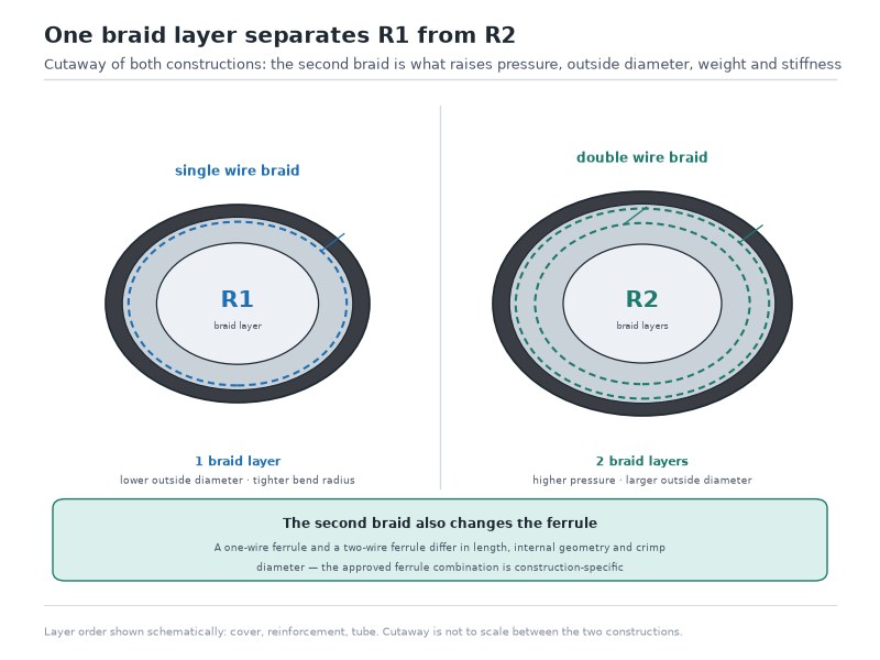
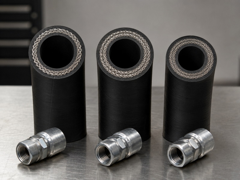
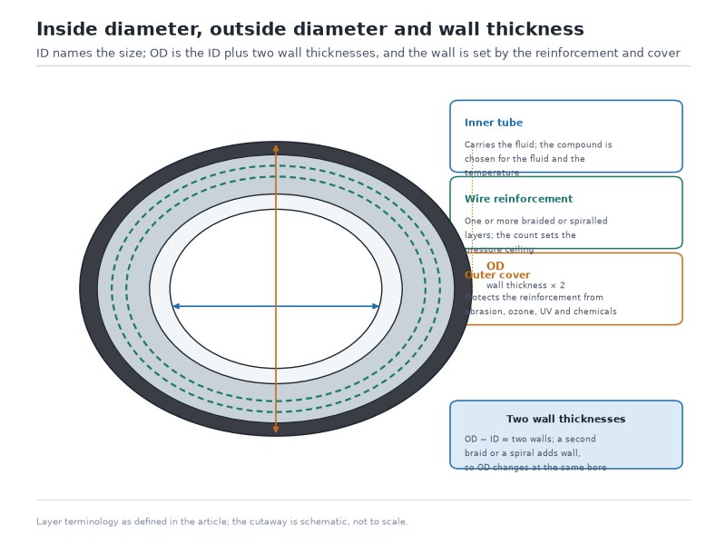
Figure 1. One braid layer separates R1 from R2. The second braid is what raises working pressure, outside diameter, weight and stiffness — and it is the reason the two hoses take different ferrules.
Table 1. R1 vs R2 in one table: published values at 1/2 inch (-08) bore. Both columns are published values for the same standard family — the R1 column from the EN 853 1SN table and the R2 column from the EN 853 2SN table — so the comparison is like for like.
| Property | SAE 100R1 (single wire braid — EN 853 1SN) | SAE 100R2 (double wire braid — EN 853 2SN) | Practical effect |
|---|---|---|---|
| Reinforcement | One braided high-tensile steel wire layer | Two braided high-tensile steel wire layers | Sets every other number in this table |
| Working pressure at -08 (1/2 in) | 16.0 MPa / 2,320 psi | 24.0 MPa / 3,500 psi | SAE 100R2 carries about 1.5 times the pressure at this size |
| Minimum burst pressure at -08 | 64 MPa / 9,280 psi | 96.5 MPa / 14,000 psi | Minimum burst is specified at four times the working pressure (EN 853 / SAE J517); the published R1 figures round to 3.95–4.00 times its own rating |
| Outside diameter at -08 | 21.4 mm max | 23.0 mm max | R2 needs 1.6 mm more clearance in clamps and guards |
| Mass at -08 | 0.45 kg/m | 0.640 kg/m | SAE 100R2 is about 42 percent heavier per metre at -08 — 0.640 kg/m against 0.45 kg/m |
| Minimum bend radius at -08 | 180 mm | 180 mm | Identical on paper, but the two-braid hose is stiffer: reaching that radius takes more force and transmits side load into the ferrule and the port |
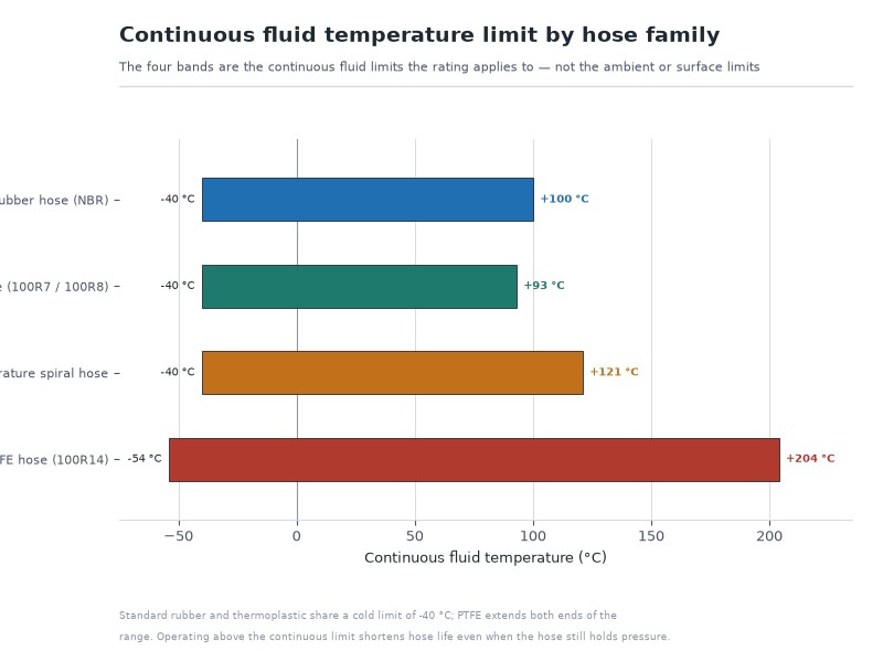
| Temperature range | -40 °C to +100 °C | -40 °C to +100 °C | Intermittent service to about +120 °C on both |
| Fittings and ferrules | Ferrule approved for one braid layer | Ferrule approved for two braid layers | Not interchangeable — the most common field error |
| Typical duty | Return, pilot, drain and light pressure lines | Main pressure lines on mobile and industrial machines | R2 is the default above roughly 2,000 psi |
The figures above are published catalogue values at 1/2 inch bore: the R1 column is read from the EN 853 1SN table and the R2 column from the EN 853 2SN table. Equivalent constructions do not always publish identical values — the same 3/8 inch bore is published at 15.7 MPa (2,280 psi) on the SAE 100R1 table and 18 MPa (2,610 psi) on the EN 853 1SN table, because each number belongs to the specification the hose was tested against. Treat any general table as the shape of the difference rather than as a substitute for the datasheet of the exact hose you are buying.
What Is R1 Hydraulic Hose, and What Is It Rated For?
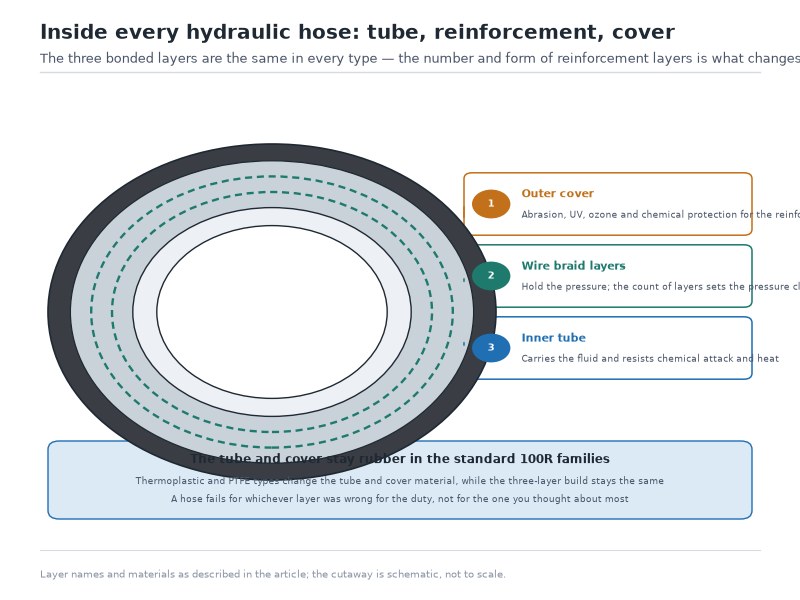
R1 hydraulic hose is a three-layer rubber hose: an oil-resistant synthetic rubber tube, one braided layer of high-tensile steel wire, and an oil-, weather- and abrasion-resistant cover. It is the medium-pressure workhorse of the SAE 100R1 and EN 853 1SN families, and on the EN 853 1SN table the 1/4 inch bore is published at 22.5 MPa (3,260 psi), falling to 4 MPa (580 psi) at 2 inch bore. The fall is not a defect — it is the direct consequence of sharing one wire layer across an ever-larger diameter.
Two properties make R1 attractive beyond its price. It is the more flexible of the two constructions, which matters on short assemblies and cramped routing, and it is lighter, so a long line puts less load on its own end fittings and on the ports it connects to. A thin, single-braid hose also bends with less force, which makes it easier to install without twisting — and twist behind the ferrule is a genuine failure cause, not a cosmetic one.
Its limitation is headroom. One braid layer spreads pressure load over fewer wires, so at a given pressure the wire sees more stress than it would in an R2, and the hose has less reserve for pressure spikes and fatigue cycling. R1 is the right choice when its published rating clears your maximum system pressure with margin; it is the wrong choice when you are relying on it to absorb shock.
What Is R2 Hydraulic Hose, and Where Does It Belong?
R2 hydraulic hose is the same three-layer build with a second braided steel wire layer added over the first. It is the SAE 100R2 / EN 853 2SN family, and it is the default hose on the pressure lines of most mobile and industrial machines. On the published EN 853 2SN table the 1/2 inch bore is rated 24.0 MPa (3,500 psi), and the family runs from 40 MPa (5,800 psi) at 1/4 inch down to 8.6 MPa (1,250 psi) at 2 inch bore.
The second braid does three things at once. It raises the shipped pressure ceiling to roughly 1.5 to 2.2 times the single-braid figure at the same bore, depending on which standard’s tables are compared. It raises impulse resistance, because the pressure load is shared across twice as many wires and the braid angles can be optimised for fatigue rather than for burst alone. And it raises kink and abrasion resistance, because the hose wall is heavier and less willing to collapse when the line is pulled around a corner or dragged over structure.
The costs are equally concrete. R2 measures slightly larger outside, is about 33 to 70 percent heavier per metre depending on size, and resists bending more, so it takes more effort to route and can push back against the fitting if the ports are misaligned. That push-back is not harmless: a stiff hose forced into position applies continuous side load to valve blocks, adapters and pump housings, and it can fatigue the hose immediately behind the ferrule where bending stress concentrates.
Hydraulic Hose R1 vs R2: Seven Differences That Matter
Once you accept that R1 has one braid layer and R2 has two, the rest of the comparison writes itself. Seven differences decide real installations, and only the first one is structural — the other six are consequences you have to live with on the machine.
1. How Many Braid Layers Does Each Hose Have?
R1 carries a single braided layer of high-tensile steel wire over the tube. R2 carries two, one wound over the other, normally braided in opposite directions. Braiding crosses the wires rather than laying them in parallel, which is what gives a braided hose its flexibility — and also what creates crossover points where wires fret against each other under repeated pressure cycling. A second layer divides that load across more wires, which is the mechanical reason R2 survives more pressure cycles at the same stress level.
2. Working Pressure: About 1.5 to 2.2 Times at the Same Bore
Working pressure is the figure printed on the cover and the first number that decides whether a hose is eligible for your line. The hydraulic hose pressure rating that matters is the one published for your exact dash size, so read it size by size rather than from a family figure. Across the standard dash sizes, R2’s published working pressure is about 1.5 to 2.2 times R1’s at the same bore — narrowest in the mid sizes at around 1.5, and reaching about 2.2 at 2 inch bore. The ratio moves with the bore because the two constructions lose pressure at different rates, and because the two published tables are drawn from different standards.
Read that ratio as capacity, not as safety: the R2 advantage is a higher pressure ceiling at the same bore, which a low-pressure return line never reaches. The practical consequence is that a system running at 2,000 psi cannot use R1 hydraulic hose in any bore larger than 1/2 inch, because its rating drops below the requirement at the next size up — while the same system can use R2 up to 1 inch bore, where the published rating is 2,250 psi; from 1-1/4 inch upward the R2 rating falls below 2,000 psi and the next step is a spiral construction. If you are replacing a hose and the only thing that changed is size, verify the rating at the new size rather than at the old one.
3. Burst Pressure: Four Times Working Pressure
Both families are built so that the standard specifies a minimum burst pressure of four times the maximum working pressure — four times the published working pressure of the hose in your hand. The familiar “4:1 safety factor” of the trade is the same ratio read the other way; EN 853 and SAE J517 themselves define a minimum burst pressure, not a margin to spend. At 1/2 inch bore the published minimum burst figures are 64 MPa (9,280 psi) for the EN 853 1SN R1 and 96.5 MPa (14,000 psi) for the EN 853 2SN R2 — each four times its own rating, not four times some shared number. Because published figures are rounded to whole megapascals, the R1 column of Table 3 computes to exactly 4.00 times at seven sizes, 4.01 at -12, and to 3.95, 3.96 and 3.98 at -05, -16 and -20; the R2 column computes to 4.00 at every size where it is published.
Surge pressure, fatigue cycling, temperature, abrasion and routing abuse all shorten the service life the hose can deliver, and a hose that has been kinked or bent below its minimum radius is already at higher risk of failure.
4. Outside Diameter and Mass: The Hidden Cost of the Second Braid
R2 measures roughly 1.6 mm larger outside in the small and mid sizes and up to about 4.7 mm larger at 1-1/4 inch, and it is heavier per metre in every size — by about 41 percent at 5/8 inch, about 49 percent at 1 inch and up to about 70 percent in the smallest bores. Table 4 gives the outside diameter, and Table 5 the mass penalty, of the second braid at every dash size from -03 to -32.
That difference sounds small until it lands in the real installation: larger outside diameter may not fit the existing clamp, guard, spiral guard or bulkhead grommet, and additional mass on a long unsupported run is mass the end fittings and ports have to carry. A long, heavy, stiff hose that is forced into an existing route is a fatigue failure waiting for its hour, not a maintenance upgrade.
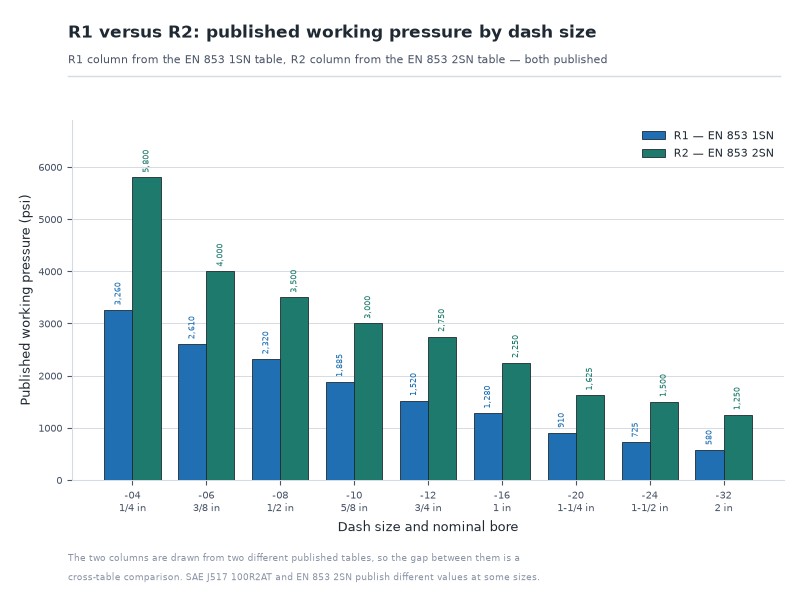
Figure 2. Published working pressure by dash size for the R1 and R2 families, computed from the two tables in this guide. The R2 ÷ R1 ratio runs about 1.5 to 1.8 from 1/4 inch to 1-1/4 inch, then rises to 2.07 at 1-1/2 inch and 2.16 at 2 inch. The ratio is a cross-table value: R2 read from the EN 853 2SN table, R1 from the EN 853 1SN table.
5. Bend Radius: The Same Number on Paper, a Different Hose in Your Hand
The published minimum bend radius for R1 and R2 is nominally the same at every dash size in the EN 853 family — 90 mm at 3/16 inch, 130 mm at 3/8 inch, 180 mm at 1/2 inch, 300 mm at 1 inch, rising to 630 mm at 2 inch. On paper, both hoses bend to the same limit.
In service the two constructions feel different: a two-braid R2 resists bending harder, so reaching the same nominal radius needs more force and the hose keeps the set it is bent into. That produces two installation risks a single-braid hose rarely shows: a twisting load transmitted into the ferrule, and continuous side load against the port when the hose is pushed into alignment. The routing habits that handle both are set out in the bend radius and routing section below.
6. Impulse Life Under Pressure Spikes
Impulse testing is the fatigue test that separates a hose that survives on a machine from one that survives on a shelf. The hose is cycled between low pressure and a square-wave impulse at 133 percent of its working pressure at elevated fluid temperature, and the number of cycles before failure is its impulse rating.
R2 is stronger here for a structural reason: two braid layers mean each wire carries roughly half the load, and the fretting at crossover points is spread across more wire. Where a circuit spikes repeatedly — a boom that stalls under load, a breaker, a press decompression, a rock drill — that difference decides how long the line lasts, and it is why the standard advice is to select on pulse profile rather than on steady pressure alone.
Two honest caveats belong here. First, SAE issues no approval lists or certificates; compliance is voluntary, and a supplier’s claim that a hose “meets 100R2” is a self-declaration until a test report says otherwise. Second, impulse life is not a simple multiple of the working-pressure ratio — it depends on braid angle, wire grade, tube compound, temperature and routing. Ask for the impulse life testing data behind the hose you are buying, not just the pressure rating.
7. Can You Use the Same Fittings on R1 and R2?
A ferrule is matched to the number of braid layers it has to grip, and it is not a generic part. The ferrule for a single-braid hose and the ferrule for a two-braid hose differ in length, in internal geometry and in the crimp diameter that seats them, and the hose manufacturer’s approved combination is the only valid one. A one-wire ferrule crimped onto two-braid hose can hold pressure on a bench test and still fail in service, because the grip is not distributed across both layers. The four rules that prevent those failures are set out under “Are R1 and R2 Fittings Interchangeable?” below.
Hydraulic Hose R1 vs R2: Pressure Ratings by Dash Size
At 1/2 inch bore, the R1 single-braid pressure rating is 16.0 MPa (2,320 psi) and the R2 double-braid rating is 24.0 MPa (3,500 psi) — about 1.5 times the R1 figure. At 1/4 inch the same two constructions are rated 22.5 MPa (3,260 psi) and 40 MPa (5,800 psi). Read these as the published EN 853 1SN and EN 853 2SN figures for the same number of braid layers, and confirm on the datasheet of the exact hose.
The rule this table enforces is simple: at a given bore R2 is rated about 1.5 to 2.2 times R1 — 1.78 at 1/4 inch, 1.51 at 1/2 inch, 2.16 at 2 inch — so a system running 2,000 psi is inside R1 up to 1/2 inch and outside it from 5/8 inch upward, while R2 covers that pressure only up to 1 inch bore (2,250 psi); at 1-1/4 inch the published rating drops to 1,625 psi. A rating figure is only valid at the bore it was published for, which is why the table is arranged by dash size rather than by family.
The R1 column is read from the published EN 853 1SN table and the R2 column from the published EN 853 2SN table, because those are the two tables suppliers and drawings cross-reference most often. SAE J517 100R2AT and EN 853 2SN describe the same two-wire braid construction, but the two standards publish different working pressures at some dash sizes; a DIN 20022 1SN or GB/T 10544 equivalent differs again. Order to the standard your drawing names, and confirm the figure for the exact dash size and standard on the datasheet before ordering. For the 100R-code view, see the SAE 100 series hydraulic hose specifications; for DIN, ISO and GB equivalents see the hydraulic hose standards guide. For the three-way 100R1, 100R2 and 100R16 decision — including the compact construction that bends to roughly half these radii — see the 100R1 vs 100R2 vs 100R16 comparison.
Table 2. Published working pressure by dash size. The R1 hydraulic hose column is read from the EN 853 1SN table and the R2 hydraulic hose column from the EN 853 2SN table. Both columns are hydraulic hose pressure ratings at the same bore, published to two different standards. The R2 / R1 ratio is a cross-table ratio — the two columns are drawn from different published tables, so read it as indicative rather than as a same-standard comparison.
| Dash size | Nominal bore | R1 working pressure (EN 853 1SN) | R2 working pressure (EN 853 2SN) | R2 / R1 ratio |
|---|---|---|---|---|
| -03 | 3/16 in | 25.0 MPa / 3,625 psi | — | — |
| -04 | 1/4 in | 22.5 MPa / 3,260 psi | 40.0 MPa / 5,800 psi | 1.78 |
| -05 | 5/16 in | 21.5 MPa / 3,120 psi | — | — |
| -06 | 3/8 in | 18.0 MPa / 2,610 psi | 27.5 MPa / 4,000 psi | 1.53 |
| -08 | 1/2 in | 16.0 MPa / 2,320 psi | 24.0 MPa / 3,500 psi | 1.51 |
| -10 | 5/8 in | 13.0 MPa / 1,885 psi | 20.7 MPa / 3,000 psi | 1.59 |
| -12 | 3/4 in | 10.5 MPa / 1,520 psi | 19.0 MPa / 2,750 psi | 1.81 |
| -16 | 1 in | 8.8 MPa / 1,280 psi | 15.5 MPa / 2,250 psi | 1.76 |
| -20 | 1-1/4 in | 6.3 MPa / 910 psi | 11.2 MPa / 1,625 psi | 1.79 |
| -24 | 1-1/2 in | 5.0 MPa / 725 psi | 10.3 MPa / 1,500 psi | 2.07 |
| -32 | 2 in | 4.0 MPa / 580 psi | 8.6 MPa / 1,250 psi | 2.16 |
Table 3. Published minimum burst pressure by dash size, with the ratio each published value computes to against its own column’s working pressure. Minimum burst is specified at four times the working pressure (EN 853 / SAE J517); the R1 hydraulic hose values that fall below 4.00 do so because published figures are rounded to whole megapascals.
| Dash size | R1 minimum burst (EN 853 1SN) | R1 burst ÷ R1 working pressure | R2 minimum burst (EN 853 2SN) | R2 burst ÷ R2 working pressure |
|---|---|---|---|---|
| -03 | 14,500 psi | 4.00 | — | — |
| -04 | 13,050 psi | 4.00 | 23,200 psi | 4.00 |
| -05 | 12,325 psi | 3.95 | — | — |
| -06 | 10,440 psi | 4.00 | 16,000 psi | 4.00 |
| -08 | 9,280 psi | 4.00 | 14,000 psi | 4.00 |
| -10 | 7,540 psi | 4.00 | 12,000 psi | 4.00 |
| -12 | 6,090 psi | 4.01 | 11,000 psi | 4.00 |
| -16 | 5,075 psi | 3.96 | 9,000 psi | 4.00 |
| -20 | 3,625 psi | 3.98 | 6,500 psi | 4.00 |
| -24 | 2,900 psi | 4.00 | 6,000 psi | 4.00 |
| -32 | 2,320 psi | 4.00 | 5,000 psi | 4.00 |
Table 2 reads published working pressure; Table 3 reads published minimum burst pressure and shows what each value computes to against that column’s own working pressure. Minimum burst is specified at four times the working pressure. Because published figures are rounded to whole megapascals, the R1 values in Table 3 compute to exactly 4.00 times at seven sizes, 4.01 at -12, and to 3.95, 3.96 and 3.98 at -05, -16 and -20; the R2 column computes to 4.00 at every size where it is published.
The R2 column follows the published EN 853 2SN table, which is also published in bar as 400 / 275 / 240 / 207 / 190 / 155 / 112 / 103 / 86 bar from -04 to -32 — the 1-1/2 inch figure being 1,500 psi / 103 bar. The bar values are the published metric column and the psi values are read from the same table. That table begins at -04, so the -03 and -05 R2 cells carry a dash: whether a 3/16 or 5/16 inch two-wire braid is published in your standard is a question for the datasheet, not for this table.
The R2 / R1 ratio is therefore a cross-table ratio, and the width of the R2 advantage in the mid sizes is smaller than the two-layer construction alone would suggest. Read it as the fastest line in this comparison, but not as a substitute for the datasheet of the hose in front of you.
Table 4. Outside diameter by dash size. R1 column: EN 853 1SN published table. R2 column: EN 853 2SN published table. Outside diameter also sets the hydraulic hose bend radius a route can achieve, because the two move together in this family. The difference column is the R2 diameter minus the R1 diameter at the same dash size, and it is what decides whether an existing clamp, guard or bulkhead grommet still fits.
| Dash size | Nominal bore | R1 outside diameter | R2 outside diameter | R2 − R1 |
|---|---|---|---|---|
| -03 | 3/16 in | 12.5 mm max | 14.1 mm max | +1.6 mm |
| -04 | 1/4 in | 14.1 mm max | 15.7 mm max | +1.6 mm |
| -05 | 5/16 in | 15.7 mm max | 17.3 mm max | +1.6 mm |
| -06 | 3/8 in | 18.1 mm max | 19.7 mm max | +1.6 mm |
| -08 | 1/2 in | 21.4 mm max | 23.0 mm max | +1.6 mm |
| -10 | 5/8 in | 24.5 mm max | 26.2 mm max | +1.7 mm |
| -12 | 3/4 in | 28.5 mm max | 30.1 mm max | +1.6 mm |
| -16 | 1 in | 36.6 mm max | 38.9 mm max | +2.3 mm |
| -20 | 1-1/4 in | 44.8 mm max | 49.5 mm max | +4.7 mm |
| -24 | 1-1/2 in | 52.1 mm max | 55.9 mm max | +3.8 mm |
| -32 | 2 in | 65.5 mm max | 68.6 mm max | +3.1 mm |
Table 5. Mass per metre by dash size. R1 column: EN 853 1SN published table. The R2 hydraulic hose column carries catalogue values for the two-wire braid class — confirm against the datasheet for the exact hose. The “R2 heavier by” column is computed by dividing the two mass columns.
| Dash size | Nominal bore | R1 mass | R2 mass | R2 heavier by |
|---|---|---|---|---|
| -03 | 3/16 in | 0.20 kg/m | 0.340 kg/m | 70% |
| -04 | 1/4 in | 0.25 kg/m | 0.372 kg/m | 49% |
| -05 | 5/16 in | 0.31 kg/m | 0.430 kg/m | 39% |
| -06 | 3/8 in | 0.36 kg/m | 0.560 kg/m | 56% |
| -08 | 1/2 in | 0.45 kg/m | 0.640 kg/m | 42% |
| -10 | 5/8 in | 0.52 kg/m | 0.732 kg/m | 41% |
| -12 | 3/4 in | 0.65 kg/m | 0.930 kg/m | 43% |
| -16 | 1 in | 0.91 kg/m | 1.360 kg/m | 49% |
| -20 | 1-1/4 in | 1.30 kg/m | 1.850 kg/m | 42% |
| -24 | 1-1/2 in | 1.70 kg/m | 2.300 kg/m | 35% |
| -32 | 2 in | 2.00 kg/m | 2.650 kg/m | 33% |
Read the two tables together and a pattern appears: the pressure advantage of R2 grows with bore size, while the mass penalty does not fall. At 2 inch bore an R2 hose carries 2.16 times the working pressure of an R1 for 33 percent more mass per metre, which is a trade most people would take. At 3/16 inch the same comparison reads 70 percent more mass, which is not a trade anybody needs to make. Where R2 becomes the wrong answer is not a matter of ratio at all — it is the three cases in the next section: return and drain lines, short assemblies between misaligned ports, and installations limited by outside diameter or weight. Not sure which dash size your circuit needs? Send us the flow and the relief setting and we will return the eligible sizes for both constructions.
The Bore at Which the Cheaper Hose Stops Qualifying
Given a target working pressure, the tables above settle the question fast. Compare the surge-inclusive requirement against the hydraulic hose pressure rating in Table 2 before reading across. What is the largest bore in which each construction still qualifies? Read down the R1 hydraulic hose column and the R2 column and the answer is a single dash size — and that answer is usually what decides whether the lighter hose is still available at the bore the flow requires.
Table 6. Largest dash size that still meets a target working pressure, read from Table 2 at the R1 (EN 853 1SN) column and the R2 (EN 853 2SN) column.
| Target working pressure | Largest R1 dash size that qualifies | Largest R2 dash size that qualifies | What it means in practice |
|---|---|---|---|
| 1,500 psi | -12 (3/4 in), 1,520 psi | -24 (1-1/2 in), 1,500 psi | R1 covers most of the range; the second braid buys bore rather than extra protection |
| 2,000 psi | -08 (1/2 in), 2,320 psi | -16 (1 in), 2,250 psi | The most common boundary: one dash size of R1 is worth two dash sizes of R2 in bore terms |
| 2,500 psi | -06 (3/8 in), 2,610 psi | -12 (3/4 in), 2,750 psi | R1 is limited to the small bores; check that the flow the circuit needs still fits |
| 3,000 psi | -04 (1/4 in), 3,260 psi | -10 (5/8 in), 3,000 psi | R1 is at its practical limit; from here the decision is between a two-braid and a spiral hose |
| 5,000 psi | No dash size | -04 (1/4 in), 5,800 psi | Above the R1 range entirely; from 3/4 inch upward this pressure needs a four-spiral construction |
The table is also the quickest way to answer the question buyers actually ask — can I drop to R1 and save weight? — because it converts a pressure requirement into a bore limit in one step. If a circuit runs at 2,500 psi and needs 3/4 inch bore for flow, R1 is out of the question at that size and R2 is the lightest construction that qualifies.
What the Second Braid Adds to the Machine: Mass, Stiffness and Side Load
The pressure advantage is the headline; the installation consequences decide whether the swap actually works. In a comparison of the two braid classes the mass and stiffness half of the decision is the half that drawings hide, so Tables 4 and 5 give the outside diameter and the mass penalty of the second braid at every dash size.
- 1.6 mm of extra outside diameter at the small and mid sizes, and 4.7 mm at 1-1/4 inch. That is enough to change whether an existing clamp, guard, spiral wrap or bulkhead grommet still fits. If it does not, the redesign is part of the change.
- About 33 to 70 percent more mass per metre, with the largest percentages in the small bores — 70 percent at 3/16 inch, 42 percent at 1/2 inch, 49 percent at 1 inch. On a long unsupported run that mass is carried by the end fittings, the adapters and the port threads.
- A stiffer hose in the same route. The published hydraulic hose bend radius is identical, but the force needed to reach it is not, and a two-braid hose keeps the set it is bent into. Pushed into alignment, it goes on loading the port.
Read together, those three numbers explain most repeat failures on machines where a single-braid hose was replaced with a two-braid hose without changing the routing.
Hydraulic Hose R1 vs R2: How to Handle Bend Radius and Routing
Because both families publish the same hydraulic hose bend radius figure at a given size, the routing rules are the same on paper — and experience shows they bite harder on R2. Three habits keep a two-braid hose out of trouble:
- Never bend closer than the published minimum, measured to the inside of the curve. Support the bend with a clamp or a formed bracket rather than letting the hose find its own line under gravity.
- Leave a straight length of at least one and a half hose diameters immediately behind the ferrule before any bend begins. This is where bending stress concentrates, and where a stiff hose cracks its cover and fatigues its reinforcement first.
- Let the hose take its natural path, then align the port to it — not the other way round. If the hose has to be forced into position, the assembly is applying permanent side load to a valve block, adapter or pump housing.
The published hydraulic hose bend radius figure is also a minimum for static installation, not an operating target. Where a hose flexes continuously — a boom line, a steering line, a hose following a moving cylinder — the working hydraulic hose bend radius should be several times larger than the static minimum, and the hose should be routed so the flexing happens along its length rather than at one point. Our hydraulic hose bend radius calculation guide covers how to read the published value, convert it into the hose length a bend consumes, and measure a radius that is already installed. That guide uses R1 and R2 for bend radius measurement conventions — inside surface and centerline — which is a different use of the letters from the hose construction codes used here.
If the tight radius is what forces the decision, the practical step is often a compact construction rather than a forced bend. Send us five items — line function; maximum pressure including surge; bore or dash size; fluid and normal plus peak temperature; routing constraints and end connections at both ends — and our engineers will confirm which construction reaches the radius your routing allows.
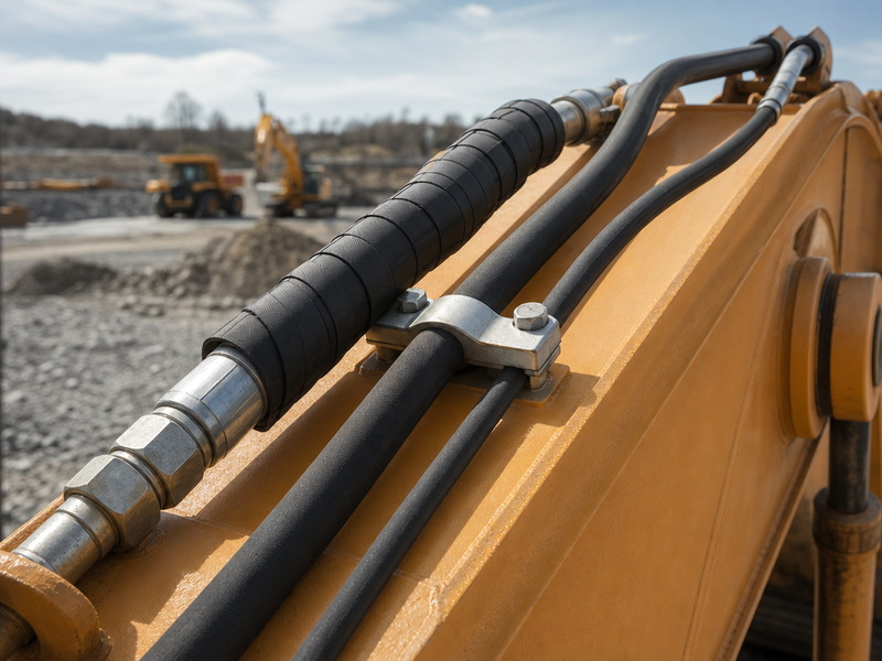
Figure 3. Route the two-braid hose the way it wants to lie. A stiffer R2 that is forced into a tight radius transmits that force into the fitting and the port instead of absorbing it.
Are R1 and R2 Fittings Interchangeable?
No. The crimp die and crimp diameter selection for a two-braid hose is a different specification from the one-braid equivalent, and the two cannot be swapped: the ferrule and insert that terminate a two-braid hose are different parts from the one-braid equivalents. A hose assembly is a system of four matched parts: hose, insert, ferrule and crimp specification. Mixing a ferrule from one series onto hose from another voids the assembly’s rating even when the parts appear to fit.
Four rules prevent the most common fitting failures.
- Use the hose manufacturer’s approved ferrule for that hose and dash size. A ferrule is matched to the number of braid layers it grips, not to the inside diameter alone.
- Read the crimp value for your hose, not for a similar-looking one. Crimp diameter, insertion depth and ferrule position come from the coupling manufacturer’s published table for that exact hose and series, so use the value published for your hose instead of copying one from a series whose outside diameter looks close.
- Match the fitting series to the pressure class. A fitting rated below the hose’s working pressure becomes the weak point, because the assembly’s rating is the lowest rating of its components.
- Check the flow path, not just the thread. Insert bore, elbow radius, adapter bore and quick-coupling bore can restrict flow even when the thread is correct, and a local restriction shows up as pressure drop and heat long before it shows up as a leak.
Which Are You? Three Ways to Use This Guide
- Specifying a new line: work the five questions under “How to Choose in Five Steps”, then read the rating at your exact dash size in Table 2.
- Replacing a failed hose: use the two-minute identification method under “How to Identify R1 and R2 on a Hose You Already Have”, then replace by specification and dash size — never by outside diameter.
- Buying for a fleet or a store: normalise the quote scope before comparing totals, and hold one two-braid series as the default.
- Diagnosing a repeat failure: a hose that fails again in the same position usually has a routing or fitting problem, not a pressure problem.
Marking
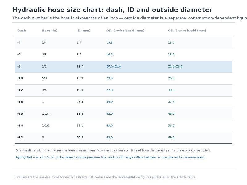
A layline gives you the construction and the bore; only the datasheet gives you the hydraulic hose pressure rating at that size. Every compliant assembly carries a marking on the cover — manufacturer, standard, bore, working pressure and a traceable identity. The dash size is the number after the hyphen, read in sixteenths of an inch, so the -8 in a 100R2AT-8 string is 8/16 inch, or 1/2 inch nominal bore — the conversion most buyers are looking for when they open a hydraulic hose dash size chart. Read the layline at receipt and record it, because marking is what links the physical hose to the certificate in your file. Our how to read a hydraulic hose layline guide explains each field printed on the cover, and the broader hydraulic hose basics guide covers layline field decoding, the quarter-year date code and the working, proof and burst pressure definitions behind the numbers.
Does R2 Always Beat R1? Three Cases Where It Does Not
The reflex answer — “two wires are safer than one” — is the most expensive half-truth in hose selection. A higher pressure ceiling does nothing for a line that never approaches it, and R2’s extra stiffness can actively cause the failure it was bought to prevent. Three situations argue for staying with R1.
Case 1: Return, drain and pilot lines. These lines sit at low pressure but often carry high flow, and their job is to keep backpressure down. Neither construction is pressure-limited here, so the choice is decided by flexibility, weight and cost — and R1 wins all three. Fitting R2 to a return line adds stiffness, mass and price for zero pressure benefit.
Case 2: Short assemblies between misaligned ports. On compact machines, a short hose between two ports that do not line up has almost no length to absorb misalignment. A flexible single-braid hose twists and bows; a stiff two-braid hose pushes back into the fitting, adapter or valve block, and that constant side load is what eventually cracks the cover and fatigues the reinforcement directly behind the ferrule.
Case 3: Space and weight limits. If the larger outside diameter of R2 does not clear the existing clamp, guard or bulkhead, the installation needs redesign, not a heavier hose. Additional mass on a long unsupported run also has to be carried by the end fittings and ports.
There is a fourth case that matters more than any of these: neither R1 nor R2 is the answer to severe impulse duty. A circuit with sharp, frequent pressure spikes — an excavator boom crowd cycle, a breaker, a press decompression, a rock drill — is the territory of four-spiral (100R12) and constant-pressure compact constructions (100R16, 100R17), which trade flexibility for far longer fatigue life. Moving from R1 to R2 in that service delays the failure without solving it.
How to Verify a 100R2 Claim When There Is No Approval List
SAE issues no approval lists and no certificates for 100R2, so “meets SAE 100R2” is a supplier’s self-declaration until documentation says otherwise. That matters most when the choice between the single-braid hose and the double-braid hose is being made on a data sheet rather than on a test bench, because a hydraulic hose pressure rating on its own says nothing about how the assembly was built or tested. Three documents move that claim from marketing to verifiable, and all three are obtainable on request without a third-party audit:
- A proof test record for the batch. The standard’s proof pressure is twice the maximum working pressure, so a record showing the assembly held it is the cheapest sanity check available.
- An impulse test report at your dash size. EN ISO 6803, at 133 percent of working pressure, at +100 °C, for a minimum of 200,000 cycles. Ask for the size and the fluid as well, because an impulse figure quoted for one size does not transfer to another.
- A ferrule-to-hose match table. The coupling manufacturer’s published combination for that exact hose and dash size, which is what makes the crimp reproducible from batch to batch.
None of the three on its own proves a hose is good; together they show that the parts were built and tested as an assembly, which is the part of a supply claim that a pressure rating alone never covers.
How to Choose in Five Steps
Any hydraulic hose R1 vs R2 decision is settled by five questions in a fixed order. Answer them out of order and you will buy a hose that meets the pressure requirement and still fails.
Step 1: Identify the line function. Establish whether the hose is a pressure line, return line, pilot line, case-drain line or suction line. The function sets the pressure and flow logic. R1 and R2 are pressure-service hoses, so for suction and return service specify a 100R4 construction with a wire helix — a high positive-pressure rating says nothing about vacuum collapse resistance.
Step 2: Establish the real maximum pressure, including surge. Use the relief valve setting, transient peaks and measured system pressure, not the reading you see during light operation. If you do not know the surge, measure it: surge is how braided hoses fail.
Step 3: Size the bore from flow, then check the hydraulic hose pressure rating at that exact size. This is the step where the decision is usually made. R1 and R2 ratings both fall as bore rises, so a construction that is comfortably adequate at 1/2 inch may be ineligible at 3/4 inch. Confirm the published rating for the R1 hydraulic hose and for the R2 construction at the size you actually need, in both pressure units your team uses.
Step 4: Confirm temperature and fluid compatibility. Both families are typically rated -40 °C to +100 °C with petroleum-based hydraulic fluid and about +120 °C intermittent. Water-based, biodegradable and phosphate-ester fluids, and sustained temperatures outside that band, may require a different tube compound or a different hose family entirely.
Step 5: Verify routing space and the fitting system. Check that the hose can follow its natural path without bending below the published minimum radius, that clamps and guards accept the outside diameter, and that the fittings, ferrules and crimp data come from the manufacturer’s approved combination for that exact hose. The assembly’s rating is the lowest rating of its components.
Selection checklist: what to send a supplier
- Line function (pressure, return, pilot, drain or suction)
- Maximum working pressure, relief setting and surge pressure
- Bore or dash size, and whether a slim OD is needed for a compact machine
- Fluid type and normal plus peak temperature
- Length, plus the ports and threads at each end
Then the four commercial and file items that decide the quote rather than the hose:
- Routing constraints: available space, minimum bend radius, clamps and abrasion protection
- Whether the line flexes in service, and how often it is connected and disconnected
- Documentation needed: proof test report, impulse test data, material certificates
- Volume, delivery schedule and whether samples are wanted for qualification
How to Identify R1 and R2 on a Hose You Already Have
Settling the question on a hose that is already in service is normally a two-minute job, and it matters before you order a replacement.
- Read the layline first. Look for `100R1`, `100R1AT`, `1SN` or `100R2`, `100R2AT`, `2SN` printed along the cover. The standard code is definitive.
- If the marking is worn, cut a clean cross-section and count the braid layers. One steel wire braid means R1; two means R2. Count layers, not thickness — a thick cover and a thin cover can hide the difference from the outside.
- Measure the bore in sixteenths of an inch to establish the dash size, and measure the outside diameter to compare against the datasheet for that size.
- Identify the hose by its layline code first, then confirm with bore and reinforcement count. Outside diameter is a cross-check: two constructions at the same dash size differ in OD, and different manufacturers differ again.
If a hose cannot be identified, treat it as unrated for pressure service. Ordering a higher-pressure replacement is not a fix if the fitting system, bore and routing are wrong — that substitution is exactly how a hydraulic hose r2 fitting ends up crimped onto the wrong hose.
What Does the Price Difference Actually Buy?
R2 costs more per metre than R1 in the same bore, and the premium is explained by what is physically in the hose: a second braid layer of high-tensile steel wire, more wire-winding time, a heavier coupling and ferrule, and a heavier assembly to test, pack and ship. What that premium buys is pressure capacity, impulse life and kink resistance — and nothing else. It does not buy a longer life on a low-pressure line.
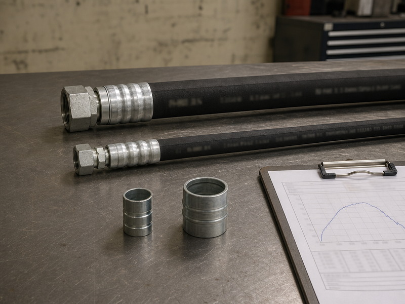
Figure 4. What a hydraulic hose quote actually covers: hose body, fitting, ferrule, crimping, proof testing, documentation, packing and lead time. Comparing headline prices without normalising the scope compares nothing.
There is no universal price per metre for either family, and any quotation that leads with one is pricing an incomplete scope. Cost is driven by factors that have nothing to do with the number of braids: bore and length, pressure class, tube and cover compound, end connections, testing, documentation, quantity and schedule. A 15,000 psi assembly and a 1,500 psi assembly of the same bore share a nominal diameter and nothing else.
Control cost by normalising scope: build one row per requirement — hose body, fittings, crimping, proof testing, documentation, packing and lead time — and mark each offer as included, excluded, optional or not stated before comparing totals. Two mistakes cost money in opposite directions: underspecifying is unsafe, while over-specifying every line to R2 pushes mass, stiffness and cost into circuits that never needed them. Repeat approved constructions and document formats where the system allows it, and ask for spares to be priced as a separate line so the decision is visible.
If you are comparing suppliers on price, send us those same five items — line function; maximum pressure including surge; bore or dash size; fluid and normal plus peak temperature; routing constraints and end connections at both ends — and we will quote hose, fittings, crimping, testing and documentation as separate lines, so the offers can be compared on the same basis.
For context on why this matters at scale: industry market research published in 2026 put the global hydraulic hose market at roughly USD 12.9 billion, rising toward USD 20 billion by 2035, according to third-party research summaries circulated in the trade press. On that volume, small specification errors on paper are large costs in the field.
Frequently Asked Questions
What is the difference between hydraulic hose R1 vs R2?
R1 has one braided layer of high-tensile steel wire reinforcement; R2 has two. That single structural difference gives R2 roughly 1.5 to 2.2 times the published working pressure of R1 at the same bore on the tables in this guide, more impulse resistance, better kink resistance, a slightly larger outside diameter, about 33 to 70 percent more mass per metre, and a higher price. Both are three-layer rubber hoses with an oil-resistant tube and a weather- and abrasion-resistant cover, and both are built so that the standard specifies a minimum burst pressure of four times the maximum working pressure (EN 853 / SAE J517).
Which is better, hydraulic hose R1 vs R2?
Neither is better in the abstract — the right one is the lightest construction that satisfies the line’s real requirements. R2 is better wherever its pressure capacity, impulse resistance or kink resistance is needed, which is most main pressure lines on mobile and industrial machines. R1 is better on return, drain and pilot lines, on short assemblies between misaligned ports, and wherever weight, outside diameter or flexibility decides the installation. Choosing R2 everywhere adds weight, stiffness and cost without adding safety.
What is the hydraulic hose pressure rating of R1 and R2 at 1/2 inch?
At 1/2 inch (-08) bore the published EN 853 1SN single-braid figure is 16.0 MPa (2,320 psi) working pressure with 64 MPa (9,280 psi) minimum burst, and the published EN 853 2SN double-braid figure is 24.0 MPa (3,500 psi) working pressure with 96.5 MPa (14,000 psi) minimum burst — a ratio of 1.51. Those figures belong to those two tables. If your drawing names SAE J517 100R2AT, or the hose in your hand carries a marking from another factory, the datasheet for that hose is the value to design to.
How do I tell an R1 hose from an R2 hose on the shelf?
Read the layline first: 100R1, 100R1AT or 1SN means one braid layer, while 100R2, 100R2AT or 2SN means two. If the print has worn off, cut a clean cross-section and count the steel wire layers instead of measuring wall thickness, then confirm the bore in sixteenths of an inch. Outside diameter is only a cross-check, because a thin-cover AT hose and a compact 100R16 both sit closer to a single-braid envelope than a standard two-braid hose does.
Is R1 or R2 the right hose for a pilot line?
R1, in almost every case. Pilot and control lines sit at low pressure relative to their bore and are valued for response and tidy routing, so the lighter and more flexible construction wins on every criterion except abrasion margin. Step up to R2 only where a pilot line is exposed to shock loading, or where a fleet standardises on one construction across the whole machine. Where the real requirement is one predictable rating in every size rather than maximum pressure, a compact constant-pressure hose such as 100R17 is the more usual answer.
What do 100R1AT and 100R2AT mean on the cover?
The 100R number is the SAE J517 hose type — one braid layer for 100R1, two for 100R2 — and the letters describe the cover rather than the pressure class. AT means a thin, abrasion-resistant cover that a crimp ferrule is pressed straight over without skiving; ST means a standard-thickness cover. A 100R1AT and a 100R1 ST hold the same pressure class but differ in outside diameter and in crimp specification, which is why the ferrule has to match the full marking and not the dash size alone.
Are R1 and R2 hydraulic hose fittings the same?
No. The ferrule and insert are matched to the number of braid layers the ferrule has to grip, and the crimp diameter, insertion depth and ferrule length differ between the two. A hydraulic hose r2 fitting crimped onto a single-braid hose, or a one-braid ferrule used on a two-braid hose, can hold pressure on a bench test and still fail in service because the grip is not distributed correctly across the reinforcement.
Do R1 and R2 have different bend radii?
In the EN 853 family the published minimum bend radius is nominally identical at each dash size — 130 mm at 3/8 inch, 180 mm at 1/2 inch, 300 mm at 1 inch, 630 mm at 2 inch. In practice R2 is stiffer and resists bending harder, so reaching that radius takes more force, the hose holds the set it is bent into, and any misalignment becomes side load on the fitting and port. Treat the hydraulic hose bend radius figure as a static minimum, and allow a working radius several times larger on hoses that flex in service.
When should I move from R2 to a four-spiral hose?
When the pressure ceiling or the pulse profile has outgrown a braided construction. At 3/4 inch bore and above, a circuit running above roughly 5,000 psi is outside the braided range altogether and needs a four-spiral 100R12 or 100R13 assembly. The same step applies at lower pressure where spikes are sharp and frequent — a boom crowd cycle, a breaker, a press decompression, a rock drill — because a braided hose reaches its impulse limit long before it reaches its working-pressure limit, and R2 only delays that outcome.
Does R2 weigh more than R1 at the same size?
Yes, at every dash size, and the penalty is proportionally largest in the small bores: about 70 percent at 3/16 inch, 42 percent at 1/2 inch, 49 percent at 1 inch and 33 percent at 2 inch on the published tables in this guide. On a long unsupported run that extra mass is carried by the end fittings and the ports, and where clamps and guards were sized for a single-braid hose it is also the reason the assembly no longer fits.
Final Verdict: Match the Braid to the Duty, Then Verify It
The hydraulic hose R1 vs R2 question has a short answer and a long tail. The short answer is that R2 carries roughly 1.5 to 2.2 times the published working pressure of R1 at the same bore, at the cost of about 33 to 70 percent more mass per metre, a slightly larger outside diameter, more stiffness and a higher price per metre. The long tail is everything that decides whether that trade is worth taking: the line function, the surge pressure you actually measured, the bore the flow requires, the fluid and temperature, the routing space, the pulse profile, and the fitting system the hose was approved to use.
Work the five steps in order and the choice usually makes itself: R1 where it is pressure-adequate and flexibility matters, R2 for main pressure lines and moderate pulsing, and something heavier than both when the circuit spikes hard and often. Then verify rather than assume — read the rating at your exact dash size, check the impulse data, and use only the hose manufacturer’s approved fitting and crimp combination for the hose you bought.
HENGHUA manufactures hydraulic hose assemblies in both constructions — single wire braid R1 and double wire braid R2 — from 1/4 to 2 inch bore, with crimped end fittings in every dash size, and with the fitting, ferrule and crimp specification approved per hose rather than assembled from mixed parts. Send us five items and our engineers will confirm the construction and quote line by line, so the offer compares with any other supplier on the same basis:
- line function
- maximum pressure including surge
- bore or dash size
- fluid and normal plus peak temperature
- routing constraints and end connections at both ends
That is how the choice between an SAE 100R1 and an SAE 100R2 assembly rests on test data rather than habit. Request a quote and free samples.
 English
  Spanish
  Portuguese
  French
  German
  Arabic
  Russian