
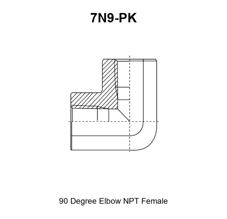
The 7N9-PK adapter is a 90° elbow hydraulic adapter with an internal NPT taper thread tapped into each end, so it presents a female pipe thread on the run and a female pipe thread on the branch. There is no male thread, no cone and no O-ring: the part is a tapped elbow that joins two male NPT pipe threads at a right angle. Its duties are the same as the straight version of the family, with one addition: it turns the connection through 90° so a line leaves a port sideways or upward instead of straight ahead.
Both tapped ends must match the mating male threads exactly in thread form, nominal size and pitch, because that match is the precondition for eliminating leakage at the conversion point. A 7N9-PK adapter with the wrong taper thread family will start on the mating thread and still weep under pressure.
Sealing principle of this series: pressure tightness is made on the thread flanks as each male taper is drawn into the tapped taper of the elbow. The joint needs a sealant applied to the male thread, or an NPTF dryseal thread pair per SAE J476. This series does not seal on a 37° flare, on a 74° cone, on an O-ring face, on an elastomeric seat or on a four-bolt flange.
Core Advantages
- 90° elbow body that changes the direction of a connection by a right angle, so a line leaves a crowded port sideways or upward.
- Internal NPT thread at both ends, so the part is used where both mating connections are male pipe threads.
- Tapped elbow with no male thread and no elastomer, so there is no cone, face or seal to crush in service.
- Port extender and swivel-free port change in one part: the elbow is turned onto the first male thread and the second male part screws in without rotating.
- 14 printed rows, Z1/8″X27 through Z2″X11.5, in equal and unequal combinations.
- Carbon steel with trivalent chromium zinc plating, or 304 / 316 stainless steel for corrosive service.
1. What a 7N9-PK Adapter Does
A 7N9-PK adapter joins two male NPT pipe ends at a right angle. One tapped thread sits on the horizontal run, marked E on the drawing, and the second sits on the vertical branch, marked F. What enters the E end leaves the F end 90° away, so the part changes direction, size and position of a connection at the same time.
The female end is a tapped thread. That means the thread is cut inside the body: the male pipe thread of the mating part is screwed into it, and the seal is formed on the flanks of that male thread as it is drawn into the taper. Nothing on the outside of the elbow seals, which is why the sealant is applied to the mating male thread. The adapter supplies the thread, the mating male part supplies the seal.
The first duty of the elbow is to move a connection out of a crowded place. A port that faces a wall, a frame or another fitting is difficult to reach with a hose tail, and the line that leaves it has to bend immediately. An elbow hydraulic adapter is screwed onto that port and presents its free tapped end in a new direction, in clear space, where the hose tail can be started squarely and the wrench has room to swing.
The second duty is a direction change with no swivel. With a tapped end at each side, the elbow is turned onto the first male thread, and the second male part is then screwed into the free end. The second part never has to rotate, so a pre-made hose assembly or a rigid tube is connected without a swivel joint and without twisting the line. Because the thread is a taper, the branch can also be clocked to the direction the line needs as the first joint is made up.
The third duty is a size change between two male pipe ends in a corner, where a straight coupling would not fit. Rows such as 7N9-08-12PK take a Z1/2″X14 male thread on one end and a Z3/4″X14 male thread on the other, and turn the run through 90° at the same time.
Because there is no seat angle and no elastomer in this series, there is nothing to deform but the threads themselves. Thread condition therefore governs the result, at both ends and at every assembly.
2. 7N9-PK Specifications
The two ends are presented as mirrored blocks. Read the E block for the run and the F block for the branch, then confirm both against the mating male threads.
2.1 Connection 1 – NPT female taper thread, E end on the run
- Thread standard and family: American tapered pipe thread NPT to ANSI/ASME B1.20.1, with NPTF dryseal threads to SAE J476 as the pressure-tight option.
- Thread size range available at E: Z1/8″X27 through Z2″X11.5, in the steps printed in table 2.5.
- Gender: female, an internal tapped thread on the horizontal run.
- Sealing method: metal-to-metal contact on the thread flanks of the mating male thread, with a sealant applied by the installer.
- Mating connection standard: a male NPT or NPTF pipe thread of the same nominal size and pitch, such as a hose tail, nipple or male stud.
2.2 Connection 2 – NPT female taper thread, F end on the branch
- Thread standard and family: American tapered pipe thread NPT to ANSI/ASME B1.20.1, with NPTF to SAE J476 as the dryseal option.
- Thread size range available at F: the same nine steps as connection 1, from Z1/8″X27 to Z2″X11.5.
- Gender: female, an internal tapped thread on the vertical branch.
- Sealing method: metal-to-metal contact on the thread flanks of the mating male thread, with a sealant applied by the installer.
- Mating connection standard: a male NPT or NPTF pipe thread of the same nominal size and pitch.
Both ends of this female adapter are tapped threads turned through a right angle; only the size differs in the unequal rows. There is no male end and no seat anywhere on the part.
2.3 Construction and Materials
The body is machined from bar stock on CNC lathes as an elbow, then drilled through on both axes and tapped with the NPT taper at each end. The hex is formed across the body so it can be held while both male threads are made up.
- Body material: carbon steel as standard; 304 stainless steel, 316 stainless steel or brass on request.
- Plating: trivalent chromium zinc plating (Cr3+) for carbon steel as standard; zinc-nickel plating available. Plating thickness and corrosion performance are confirmed per order rather than published as a series figure.
- Seal material: this thread adapter carries no elastomer, no O-ring and no bonded washer. Pressure tightness comes from the thread pair plus the sealant chosen by the installer.
- Machining process: bar-stock turning, drilling on two axes, NPT taper tapped and gauged at both ends, then deburred.
- Hex feature: a single hex (S1) across the body, from 16 mm to 70 mm across flats depending on size. There is no bulkhead feature and no swivel in this series.
2.4 Pressure and Temperature
Working pressure for a 7N9-PK adapter is not set by the series code. It is governed by the thread size, the wall thickness of the elbow, the sealing method and the material selected, and it is limited by the two mating male threads. Working pressure for these sizes is confirmed per order by HENGHUA engineering, based on the thread size, sealing method and material selected.
Temperature is a question of the body material and the sealant rather than of an elastomer, because the part contains none. Published material ranges of the elastomers used elsewhere in the same circuit are approximately -30°C to +100°C for NBR, -20°C to +200°C for FKM (Viton-type) and -40°C to +120°C for EPDM. Carbon steel with zinc plating suits general hydraulic service; specify 304 or 316 stainless steel for corrosive or offshore environments.
2.5 Part Number and Dimension Table
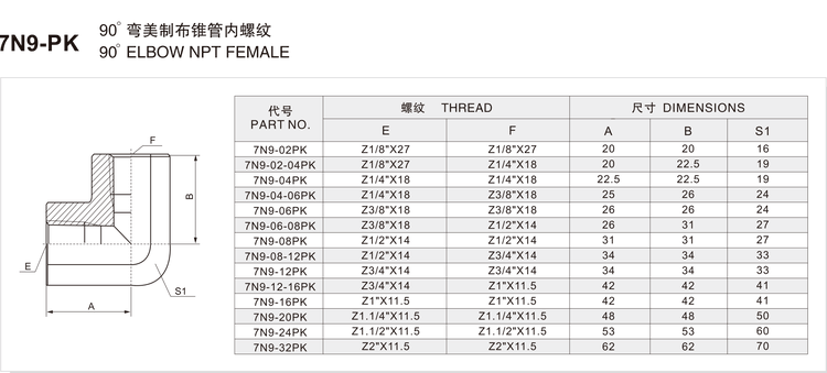
The table below is the complete printed size range of the 7N9-PK series. All dimensions are in millimetres. Both the E and the F column describe an internal tapped thread.
| PART NO. | E | F | A | B | S1 |
|---|---|---|---|---|---|
| 7N9-02PK | Z1/8″X27 | Z1/8″X27 | 20 | 20 | 16 |
| 7N9-02-04PK | Z1/8″X27 | Z1/4″X18 | 20 | 22.5 | 19 |
| 7N9-04PK | Z1/4″X18 | Z1/4″X18 | 22.5 | 22.5 | 19 |
| 7N9-04-06PK | Z1/4″X18 | Z3/8″X18 | 25 | 26 | 24 |
| 7N9-06PK | Z3/8″X18 | Z3/8″X18 | 26 | 26 | 24 |
| 7N9-06-08PK | Z3/8″X18 | Z1/2″X14 | 26 | 31 | 27 |
| 7N9-08PK | Z1/2″X14 | Z1/2″X14 | 31 | 31 | 27 |
| 7N9-08-12PK | Z1/2″X14 | Z3/4″X14 | 34 | 34 | 33 |
| 7N9-12PK | Z3/4″X14 | Z3/4″X14 | 34 | 34 | 33 |
| 7N9-12-16PK | Z3/4″X14 | Z1″X11.5 | 42 | 42 | 41 |
| 7N9-16PK | Z1″X11.5 | Z1″X11.5 | 42 | 42 | 41 |
| 7N9-20PK | Z1.1/4″X11.5 | Z1.1/4″X11.5 | 48 | 48 | 50 |
| 7N9-24PK | Z1.1/2″X11.5 | Z1.1/2″X11.5 | 53 | 53 | 60 |
| 7N9-32PK | Z2″X11.5 | Z2″X11.5 | 62 | 62 | 70 |
What each column means
- PART NO. – the HENGHUA part number. The prefix
7N9marks the NPT female family in the 90° elbow body, and the suffixPKmarks this elbow variant. One size code means an equal-ended elbow; two size codes separated by a dash mean the run takes the first size and the branch the second. - E – the tapped thread of connection 1, on the horizontal run.
Zmarks the American tapered pipe thread, the fraction is the nominal pipe size and the number afterXis the pitch in threads per inch, soZ3/8"X18is a 3/8″ NPT internal thread at 18 threads per inch. - F – the tapped thread of connection 2, on the vertical branch, in the same notation.
- A – the overall horizontal length of the elbow in millimetres, measured on the run as marked on the series drawing.
- B – the overall vertical height of the elbow in millimetres, measured from the centre of the run to the outer face of the branch. In the equal-ended rows A and B are identical.
- S1 – the hex across flats in millimetres, the wrench size used to hold the body while both male threads are made up.
Thread size and dash chart
The dash code is the size step. The equal-ended rows of this series are:
| Size code | Tapped thread | Equal-ended part number | Hex S1 (mm) |
|---|---|---|---|
| 02 | Z1/8″X27 | 7N9-02PK | 16 |
| 04 | Z1/4″X18 | 7N9-04PK | 19 |
| 06 | Z3/8″X18 | 7N9-06PK | 24 |
| 08 | Z1/2″X14 | 7N9-08PK | 27 |
| 12 | Z3/4″X14 | 7N9-12PK | 33 |
| 16 | Z1″X11.5 | 7N9-16PK | 41 |
| 20 | Z1.1/4″X11.5 | 7N9-20PK | 50 |
| 24 | Z1.1/2″X11.5 | 7N9-24PK | 60 |
| 32 | Z2″X11.5 | 7N9-32PK | 70 |
No note lines are printed under this table.
3. How to Read a 7N9-PK Part Number
A 7N9-PK part number has three elements: the family prefix, one or two size codes and the elbow suffix.
The prefix 7N9 identifies the family: the elbow version of the tapped female adapter, with an internal NPT taper thread at both ends. In the same catalogue the number 9 in the second position marks an elbow, while a straight body of the same thread family carries the prefix without it. The suffix PK marks the elbow variant of that family, so the complete code reads as the 90° version of the tapped female NPT adapter.
The first size code is the E end on the run and the second, when present, is the F end on the branch. Both are pipe dash numbers: 02 means 1/8″, 04 means 1/4″, 06 means 3/8″, 08 means 1/2″, 12 means 3/4″, 16 means 1″, 20 means 1.1/4″, 24 means 1.1/2″ and 32 means 2″.
Worked example: 7N9-08-12PK.
7N9– 90° elbow body of the NPT female family.08– connection 1 on the run is the tapped Z1/2″X14 thread.12– connection 2 on the branch is the tapped Z3/4″X14 thread.PK– elbow variant suffix.- From the table: A is 34 mm, B is 34 mm and the hex S1 is 33 mm.
A buyer ordering 7N9-08-12PK therefore receives a tapped elbow that couples a 1/2″ male pipe thread to a 3/4″ male pipe thread through a right angle, with a 33 mm hex for holding the body. If a different suffix appears on your drawing, quote the full part number including it.
4. Installation and Fitment
An NPT joint is made by drawing a tapered male thread into a tapered female thread until the flanks lock, so tightening is a feel-and-angle operation rather than a flat torque figure. HENGHUA does not publish a single torque figure for the series. Follow the port maker’s recommendation, or confirm the figure with HENGHUA per order.
Clock the branch first. Decide which way the branch has to point before the first joint is tightened, because the taper lets the elbow be rotated as it is made up. Bring the first male thread in finger-tight, turn the body until the branch faces the required direction, then hold the hex S1 and snug the joint.
Sealant, not tape fragments. Thread preparation matters more on this series than on a flared or O-ring family, because the thread is the seal at both ends. Clean both male threads, dry them, and apply a sealant compatible with the fluid and the system temperature. Leave the first thread at each entry clean so no tape fragment can enter the circuit.
Contamination and reuse. Cap both tapped ends before storage, because debris that reaches the thread flanks scores them. The body can be reused if both tapped threads are undamaged, but the joint is made up again with fresh sealant because the old sealant no longer fills the flanks.
Common fitment errors and their symptoms:
- Forcing an NPT male thread into a BSPT tapped end. Symptom: the threads bind after two or three turns and then weep.
- Over-tightening to swing the branch round. Symptom: a cracked port boss or a split tapped thread, because a forced taper generates high hoop stress.
- Leaving the elbow unsupported on a long lever arm. Symptom: the joint loosens under vibration and weeps at the run.
- Reusing the joint without renewing the sealant. Symptom: a slow weep that grows with thermal cycling.
Six-step assembly
- Confirm that both mating parts are male NPT or NPTF threads of the same nominal size and pitch as the E and F ends.
- Inspect both tapped threads for nicks and debris, and check the taper with a thread gauge where available.
- Clean both tapped threads and the mating male threads, and remove old sealant.
- Apply the selected sealant to the first male thread, starting one thread back from the end.
- Fit the elbow hand-tight, clock the branch to the required direction, hold the hex S1 and snug the joint without forcing it.
- Apply sealant to the second male thread and make up the branch joint, then leak-check both ends at the system pressure and re-check after the first thermal cycle.
5. Applications and Industries
Application tags for this series: hydraulic systems, water jetting, oil and gas, industrial equipment, construction machinery, agriculture, marine, material handling. An NPT adapter of this type is specified by its two pipe threads and its outlet direction rather than by industry, so one part serves several sectors.
Ports that face a wall or a frame. When a port points at an obstruction, this elbow hydraulic adapter moves the line into clear space through a right angle, so the hose tail can be started squarely and the line run does not chafe against the structure.
Corner routing on mobile machinery. In engine bays and under-machine installations, a 90° elbow keeps a line tight to the structure instead of looping, which is why the 7N9-PK adapter is a common item in service stock.
Direction change without a swivel. Where a pre-made hose assembly cannot be rotated, the elbow is turned onto the fixed male thread first and the assembly is then screwed into the free end. The line stays aligned and the circuit needs no swivel joint.
Repair and replacement. Maintenance crews keep equal-ended rows on the shelf as corner stock, because a damaged male thread on a line can often be recovered by coupling through a 7N9-PK adapter rather than replacing the whole line.
6. Replacement and Cross-Reference Guide
Cross-reference for this series is organised by standard and sealing method, never by brand. Two thread adapter types interchange only if the thread form, the nominal size, the pitch, the gender and the outlet direction all match.
A 7N9-PK adapter is a female-to-female NPT elbow under ANSI/ASME B1.20.1, with a tapped thread on the run and on the branch. It is not the same part as the straight female adapter of the same thread family, because the straight version does not change direction. It is not interchangeable with a JIC part, which seals on a 37° or 74° seat under SAE J514, nor with an ORFS part, which seals a flat face against an elastomeric O-ring under SAE J1453, nor with a BSPT part, which is a 55° taper thread under ISO 7-1.
To identify the correct replacement, measure three things.
- Thread. Measure the outside diameter and pitch of each mating male thread, and confirm that both ends of the replacement are the same nominal size and pitch.
- Direction and geometry. Confirm that the branch leaves the run at 90°, and record A and B so the replacement fits the same envelope. A straight coupling and a 45° elbow are not substitutes.
- Thread form. Confirm that each port is a 60° NPT taper and not a 55° BSPT taper or a straight thread. A straight thread with an O-ring groove belongs to the SAE J1926 or ISO 6149 family and needs a different part.
Where the mating port standard is not NPT, a cross standard adapter of the same size is the correct part rather than a forced thread. Record the measurements with the part number so HENGHUA can match a printed size code.
7. Ordering, Packaging and Delivery
To order, give the following information:
- Series code:
7N9-PK. - Full part number, for example 7N9-08-12PK, taken from table 2.5.
- The two tapped thread sizes, read from the E and F columns.
- The required branch direction, so the elbow is clocked correctly at assembly.
- Sealant or dryseal thread requirement, if the joint is specified as NPTF.
- Body material and plating: carbon steel with trivalent chromium zinc plating, zinc-nickel plating, or 304 or 316 stainless steel.
- Quantity, destination and the packing format required.
Packaging formats: bulk cartons for line-side consumption, small boxes for distributor shelves and labelled bags for service kits, each labelled with the part number, the thread sizes and the quantity. Sample orders and first-article parts are available for OEM programmes, including drawing-based manufacture of specials.
Lead time is confirmed per order and depends on size, material, plating and quantity. As a hydraulic adapter manufacturer and supplier, HENGHUA can quote this NPT adapter, the matching sealant recommendation and the packing format as one supply.
8. FAQ
Why is a 7N9-PK adapter female at both ends?
A female-only design is used where both mating parts are male pipe threads, and where the line has to be connected without rotating either side. The elbow is turned onto the first male thread and the second male part then screws into the free tapped end, so the part changes direction and size without adding a swivel joint. Both ends are tapped threads, so this thread adapter seals on the flanks of the mating male threads.
What is the difference between JIC 37° flare and ORFS, and which should I use?
A JIC 37° flare joint seals metal-to-metal on a 37° conical flare face under SAE J514. An ORFS joint seals a flat face against an elastomeric O-ring under SAE J1453. Choose the family that matches the port already on the equipment, because the two are not interchangeable. This series is in neither family: it is a taper pipe thread that seals on the thread flanks.
Can NPT and BSPT be interchanged?
No. NPT is a 60° taper pipe thread under ANSI/ASME B1.20.1, and BSPT is a 55° taper pipe thread under ISO 7-1. The form, angle and pitch differ, so the two will not seal even when a few threads start by hand. Use the thread the port is machined to, and order a cross standard adapter when the two sides differ.
How do I identify the correct 7N9-PK size?
Measure the outside diameter and pitch of both mating male threads, then read across the E and F columns of table 2.5. When both threads match a printed row, that row is the correct part number. Confirm the thread form as well, because a straight thread with an O-ring groove looks similar at a glance but belongs to a different family.
What seal material should I select for my fluid and temperature?
This part contains no elastomer, so the material decision is the sealant rather than an O-ring. Select a sealant compatible with the fluid and the system temperature, and apply it to the mating male threads. If the same circuit uses elastomer-sealed components, the published ranges are approximately -30°C to +100°C for NBR, -20°C to +200°C for FKM (Viton-type) and -40°C to +120°C for EPDM.
How is the working pressure of this adapter determined?
Working pressure is not fixed by the series code. It is governed by the thread size, the wall thickness of the elbow, the sealing method and the material selected, and it is limited by the two mating male threads. Working pressure for these sizes is confirmed per order by HENGHUA engineering, based on the thread size, sealing method and material selected.
Can the branch be rotated to face a different direction?
Yes. The end threads are NPT tapers, so the elbow can be turned while the first joint is being made up and stopped when the branch faces the required direction. Clock the branch before the first joint is finally tightened, then hold the hex S1 while the second male thread is made up.
What is the minimum order quantity and can I get samples?
Minimum order quantity depends on the size code, the material and the plating, so it is confirmed with the quotation rather than published as one series figure. Samples and validation parts are available for OEM and distributor evaluation, including specials made to a drawing.
Send your requirement to HENGHUA
Send the part number, both tapped thread sizes, the branch direction, the sealant or dryseal requirement, the material and plating, and the quantity. HENGHUA confirms the match to the printed table, the seal options and the delivery schedule, and quotes the 7N9-PK adapter that fits your circuit.
Related series in the same family: the 7N adapter (straight) and the 5N9 adapter (90° elbow). Browse the full Hydraulic Adapters range for the complete SAE J514 JIC, NPT, ORFS and ISO 6162 flange families.


 English
  Spanish
  Portuguese
  French
  German
  Arabic
  Russian