
Hydraulic hose for construction equipment is specified by matching one pressure class, one reinforcement construction and one fitting standard to each circuit. Boom, stick, bucket, travel, pilot and return lines are not interchangeable, and treating them as one specification is the most common source of premature failure and of unplanned replacement cost.
On a typical 20-ton excavator the main relief valve is set between 4,000 and 5,800 PSI. Two-wire braid covers the pressure lines of compact and mid-size machines, while four-spiral construction covers machines above roughly 30 tons.
This guide sets out how to read a machine’s duty cycle, pick reinforcement and dash size, and get the fitting thread right. It also covers abrasion and impact protection, the inspection interval a site crew will actually follow, and the cost and sourcing decisions that turn it all into a workable replacement programme.
1. What Does a Construction Equipment Hydraulic Hose Have to Survive?
A construction equipment hydraulic hose lives a harsher life than any hose on a factory floor. It flexes at a pivot several hundred times a shift, drags across rock and rebar, sees pressure spikes well above the relief setting, and works outdoors in dust, mud, ozone and ultraviolet light. Specification starts from that environment, not from the pump rating alone.
Hydraulic hose on mobile machinery is a consumable item with a duty cycle, which is why the same nominal hose can last five years on a crane and five months on a demolition excavator. The four loads that shorten life on site are mechanical abrasion, flex fatigue at pivots, pressure and flow shock, and environmental attack on the cover.
Applies to: hydraulic hose on mobile construction machinery, from compact machines up to mining-class drilling rigs. Does not cover: fixed hydraulic pipework inside a plant or factory, which works a steadier duty than the site conditions this guide addresses.
The machine classes below are the ones a construction fleet actually runs. They are grouped by the pressure envelope their main circuits work in and by the hose construction that normally fits.
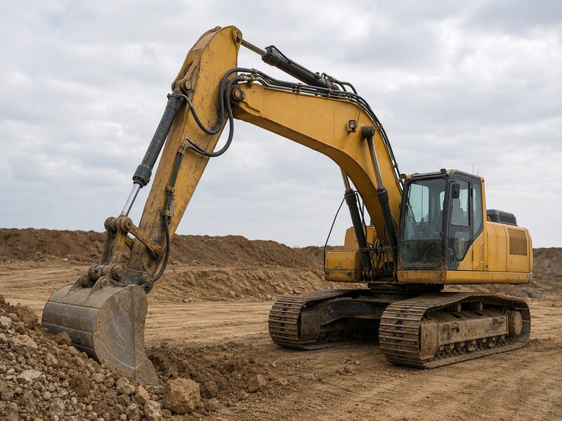
Figure 1. Boom and stick hose runs on an excavator: the most exposed, most frequently replaced hydraulic hose on any construction machine.
Table 1. Construction machine classes, their typical main-circuit pressure, and the hose construction that normally fits (confirm the relief setting published for your exact model before ordering; where the 25% margin in section 4 runs out, the circuit moves up one class)
| Machine class | Typical main relief pressure | Common hose construction | Typical dash sizes | Where the hoses fail first |
|---|---|---|---|---|
| Mini excavator (1-3.5 tons) | 2,500-3,500 PSI | Two-wire braid, 100R2 / EN 853 2SN | -4 to -8 | Boom pivot flex and bucket linkage chafe |
| Mid-size excavator (5-30 tons) | 4,000-5,000 PSI | Two-wire braid, 100R2 / 2SN | -6 to -12 | Boom-to-stick contact points |
| Large excavator (above 30 tons) | 4,000-5,800 PSI | Four-spiral, 100R12 / EN 856 4SP, 4SH | -12 to -20 | Turret entry and stick cylinder runs |
| Wheel loader (front end loader) | 3,000-4,500 PSI | Two-wire braid, 100R2 / 2SN | -8 to -16 | Lift-arm pivot and bucket linkage |
| Skid steer loader | 2,500-3,500 PSI | Two-wire braid, 100R2 / 2SN | -6 to -10 | Attachment quick-coupler and lift cylinders |
| Backhoe loader | 3,000-4,000 PSI | Two-wire braid, 100R2 / 2SN | -6 to -12 | Swing and stabiliser circuits |
| Dozer and crawler loader | 3,000-4,500 PSI | Two-wire braid or four-spiral | -10 to -20 | Blade tilt and ripper lines |
| Concrete pump boom | 3,500-5,000 PSI | Four-spiral, 4SP or 100R12 | -8 to -16 | Boom joint transitions |
| Mobile crane | 3,500-5,000 PSI | Two-wire braid or four-spiral | -8 to -16 | Outrigger and winch supply lines |
| Drilling rig and mining class | 5,000 PSI and above | Four-spiral or heavy spiral, 100R13 / 100R15 | -12 to -32 | Feed and rotation circuits |
Two practical consequences follow from Table 1. First, a fleet that stocks only one construction class (one reinforcement family) will either over-specify small machines or under-specify large ones; both are expensive, and the second is unsafe. Second, the dash-size range a machine needs is narrow enough to plan for, which is what makes fleet standardisation possible in section 11.
2. Why Do Construction Equipment Hoses Fail Faster Than Fixed Plant Hoses?
The large majority of hydraulic hose failures on construction machinery are caused by external damage rather than by internal pressure, and abrasion is the single largest contributor. The mechanisms below explain the gap between the service life a hose is rated for and the service life it delivers on a job site.
The distinction matters because the two families of cause need opposite fixes. External damage is answered by routing, clamping and protective sleeving; internal degradation is answered by correct reinforcement selection and fluid condition. Treating an abrasion failure by buying a higher pressure hose wastes money and fixes nothing.
The failure modes below are the ones that recur across construction fleets, listed with the site condition that produces each and the control that addresses the cause.
Table 2. Failure modes that recur on construction and excavator hydraulic hoses, with the control that addresses each cause
| Failure mode | Site condition that produces it | How it shows up | Control that addresses the cause |
|---|---|---|---|
| Abrasion and chafing | Hose rubbing on the boom, on a clamp edge, or on another hose through every cycle | Cover worn through to the reinforcement; shiny flat spots | Sleeving or spring guard at every contact point, plus correct clamp spacing |
| Flex fatigue at a pivot | Boom, stick and bucket joints folding the hose close to its minimum bend radius each cycle | Cracks or a kink immediately behind the ferrule (the crimped metal collar) | Match published bend radius to the tightest routing point; move the clamp, not the hose |
| Pressure spike damage | Boom lowered fast under load, relief valve lifting repeatedly, shock from a sudden bucket stop | Repeated bursts in the same location; bulging reinforcement | Verify the relief setting against the lowest component rating; slow the valve that creates the spike |
| Fluid injection injury risk | Small leak at a crimp or seal that is inspected while the system is still pressurised | Fine jet or mist rather than a drip | Depressurise before inspection; use cardboard or wood to search for leaks |
| Ozone and UV cover cracking | Continuous outdoor exposure; hose stored on a machine in sunlight for years | Fine crazing and cracks on the cover surface | Choose an ozone-resistant cover compound; treat cracking as a scheduled replacement signal |
| Cold-start stiffness | Machine left overnight in sub-zero conditions and started under load | Cover cracking at the pivot; kinked hose after the first cold cycle | Cold-flexible construction and an idle warm-up before full load |
| Impact and crushing | Falling rock or debris, hose driven over, bucket striking the line | Flattened or dented hose; reinforcement damage with intact cover | Re-route away from the swing path; fit impact-resistant guarding |
| Contamination at assembly | Hose cut and crimped in a site workshop without caps or flushing | Premature pump and valve wear after a hose change | Cap and plug on removal; purchase pre-crimped and pressure-tested assemblies |
| Wrong fitting standard | JIC hose fitted to a metric port with an adapter to make it reach | Weeping seal, damaged threads, repeat leaks at the same joint | Identify the machine’s thread family first, then order the matching assembly |
| Age-related tube hardening | Heat and oil exposure over years, even with no visible external damage | Inner tube cracked or flaking; reinforcement separation | Cap service life by calendar age as well as by inspection result |
The ten failure modes in Table 2 are not equally costly. Abrasion, flex fatigue and cold-start damage together account for most of the hose replacement work on a construction site. That is why the routing and protection decisions in section 7 usually save more money than any change to the hose itself.
3. How Do You Size a Hose for an Excavator, Loader or Skid Steer Circuit?
Sizing a hydraulic hose for excavator and loader circuits means choosing the smallest inner diameter that keeps fluid velocity inside the acceptable band for that circuit type. An undersized line restricts flow, slows the function and heats the oil, while an oversized line adds weight, stiffness and cost without improving performance.
The industry figure that drives the choice is velocity, expressed in feet per second for pressure, return, suction and pilot lines. Higher velocity means higher pressure drop and more heat; lower velocity means a larger, heavier, more expensive hose and more oil volume to move.
Choose by circuit function rather than by machine brand:
- Pressure lines (boom, stick, bucket, travel): keep velocity in the 15-20 ft/s (4.6-6.1 m/s) band.
- Return lines: 10-15 ft/s (3.0-4.6 m/s) keeps back pressure low.
- Suction lines: 4-6 ft/s (1.2-1.8 m/s) prevents cavitation at the pump inlet.
- Pilot and signal lines: 10-15 ft/s (3.0-4.6 m/s) with small dash sizes.
Convert the target velocity into an inner diameter, then round up to the nearest dash number. Table 3 below is that conversion chart. The dash number is the inner diameter in sixteenths of an inch, so the number on the hose cover is also the number that has to match the fitting.
Table 3. Dash number to inner diameter conversion and the circuits each size normally serves on construction machinery
| Dash number | Inner diameter (in) | Inner diameter (mm) | Typical construction machine use |
|---|---|---|---|
| -4 | 1/4 | 6.4 | Pilot lines, small auxiliary circuits, mini excavator pilot runs |
| -6 | 3/8 | 9.5 | Compact excavator boom and stick lines, return lines |
| -8 | 1/2 | 12.7 | Mini and small excavator pressure lines, skid steer lift circuits |
| -10 | 5/8 | 15.9 | Skid steer and backhoe pressure lines |
| -12 | 3/4 | 19.1 | Mid-size excavator boom and stick lines, loader lift circuits |
| -16 | 1 | 25.4 | Large excavator boom lines, loader main return lines |
| -20 to -32 | 1-1/4 to 2 | 31.8-50.8 | Mining-class boom lines, main supply and return runs |
Order replacement assemblies by centre-to-centre distance between the two fitting seal faces rather than by overall length, because end angles make overall length unreliable. Photograph the routing and note both end angles before removing the old hose.
When the printed marking has been abraded away, the inner diameter can still be recovered by measuring the fitting opening with a caliper. A 3/8 inch hose reads about 0.375 in (9.5 mm). The full measurement procedure is set out in our guide to measuring a hydraulic hose, and the sizing calculation itself is worked through in the hydraulic hose sizing guide.
4. What Pressure Rating Should You Specify for Site Conditions?
A hydraulic hose pressure rating has to beat the highest pressure the circuit can actually reach, not the pressure it normally runs at. On construction machinery the highest pressure is the relief valve setting plus the transient spike that occurs when a loaded function is stopped or reversed quickly. It is that spike which bursts hoses that looked correctly rated on paper.
Three numbers govern the choice, and they are often confused with one another:
- Working pressure. The continuous pressure the hose is rated to carry, printed on the cover and quoted in the standard. This is the number you compare against the machine’s relief setting.
- Proof pressure. A factory test pressure, typically about twice the working pressure, applied to every assembly before it leaves the works.
- Minimum burst pressure. The pressure at which the hose is expected to fail, which the SAE J517 100R series sets at four times the working pressure. A 4,000 PSI hose is therefore required to survive roughly 16,000 PSI before bursting.
The familiar rule of thumb on site is a 25% margin between the relief setting and the hose’s rated working pressure. Treat it as a target rather than a guarantee. Work the arithmetic against Table 1 and Table 4. A 4,000 PSI relief setting asks for 5,000 PSI of hose, the top of the two-wire braid band. Above that figure the margin is gone and the circuit moves up one class. The margin absorbs the spike, covers the pressure drop the relief setting was chosen to allow, and keeps the hose away from the top of its envelope during normal work.
Two further checks belong with the rating decision. The first is that a hose is only as strong as its assembly. A crimped ferrule that was not matched to the hose and fitting combination loses a large part of the rated performance, so the rating applies to the finished assembly rather than to the length of hose.
The second check is impulse life, the property that separates a hose which survives a season from one which survives years on a high-cycle circuit. Impulse life is measured by cycling the assembly between low and high pressure at a set operating temperature and recording the number of cycles before failure. Baseline requirements sit in the hundreds of thousands of cycles, and premium constructions are built for a longer cycle life. Read the cycle count as a comparison between constructions rather than as a service-life prediction for one machine, because duty cycle, temperature and fluid condition all move the real figure.
The relationship between the three pressure numbers, and how to read them off a cover marking, is covered in more detail in our explanation of working pressure versus burst pressure.
5. Which Reinforcement Construction Fits Which Machine Class?
Reinforcement construction sets the pressure envelope, the bend radius and the impulse life of a hydraulic hose at the same time, and it is the decision buyers most often get wrong in both directions. Two families cover almost all construction machinery: wire braid for small and mid-size machines, and wire spiral for large, high-cycle and high-pressure circuits.
A hydraulic hose is built from three layers: an inner tube that carries the fluid, a reinforcement layer that carries the pressure, and an outer cover that protects both. The construction names in Table 4 describe the reinforcement layer.
The distinction is mechanical rather than cosmetic. In a braided hose the wire strands interweave, which gives flexibility and a short bend radius. In a spiral hose the wire layers are wound in alternating directions without weaving, which gives higher burst strength and better impulse life at the cost of stiffness and a larger bend radius.
Table 4. Reinforcement families used on construction and excavator hydraulic hose, with their pressure envelopes and the machines each normally serves
| Construction | Standards | Typical working pressure | Typical impulse capability | Where it is used |
|---|---|---|---|---|
| One-wire braid | SAE 100R1, EN 853 1SN | 1,500-3,000 PSI | Moderate | Return lines, pilot and low-pressure circuits on compact machines |
| Two-wire braid | SAE 100R2, EN 853 2SN | 3,000-5,000 PSI | High | Standard boom, stick and bucket pressure lines on mini and mid-size equipment |
| Compact two-wire braid | SAE 100R16, 100R17 | 3,000-5,000 PSI | High | Tight-routing pressure lines where bend radius is the constraint |
| Four-spiral | EN 856 4SP, 4SH, SAE 100R12 | 4,000-5,800 PSI | Very high | Large excavator boom and stick lines, concrete pump booms |
| Heavy spiral | SAE 100R13, 100R15 | 5,000 PSI and above | Very high | Mining-class and drilling circuits, main supply lines |
| Constant-pressure family | ISO 18752, grades A to D | 1,000-6,000 PSI depending on grade | Graded by impulse life | Modern machines specified to a single constant-pressure standard across sizes |
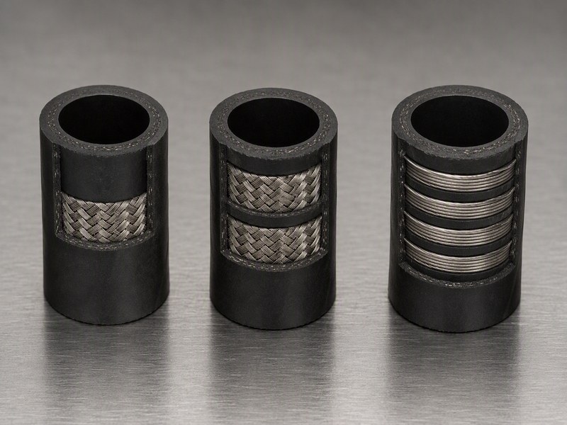
Figure 2. Reinforcement families side by side: braided layers interweave for flexibility, spiral layers alternate direction for higher burst strength and impulse life.
ISO 18752 deserves a note because it changes how a specification is written. It is a constant-pressure family, meaning the working pressure does not step down as the hose gets larger, and its grades A to D are ranked by impulse life rather than by pressure alone. For an equipment owner the practical meaning is that a machine specified to a high grade of ISO 18752 can use the same pressure rating across the whole dash-size range, which simplifies spare-part planning considerably.
In five years of supporting construction fleets, one pattern repeats often enough to be worth stating. Compact machines up to about 3.5 tons almost always run two-wire braid, machines from 5 to 30 tons run two-wire braid or four-spiral depending on the circuit, and anything above 30 tons moves to spiral construction across the pressure lines.
When the class printed on the hose you are replacing is legible, matching it and stepping up one class is the safest default. The trade-off between the two families, including where each one wins on cost, is set out in our comparison of two-wire braid and four-wire spiral hose. Both families are also supplied as finished assemblies: SAE 100R2 two-wire braid hose for compact and mid-size machines, and EN 856 4SP four-spiral hose for large excavators and concrete pump booms.
6. Which Fittings and Threads Do Construction Machines Use?
Fitting thread families are the single most common source of ordering errors on construction hose. The wrong thread does not fail loudly; it weeps, damages the port, and gets replaced twice.
Five families cover virtually every construction machine in service:
- JIC 37 degree flare. A metal-to-metal cone seal, common on older American machines and general-purpose lines.
- ORFS (O-ring face seal). An O-ring seated in the fitting face, standard on modern American and Japanese machines and preferred where vibration is continuous.
- Metric DIN 2353 (24 degree cone). Light and heavy series, dominant on Komatsu, Hitachi and most Chinese compact machines.
- BSP (BSPP parallel or BSPT tapered). Found on European machines and on export models built to a European specification.
- NPT and NPTF pipe thread. Tapered, self-sealing, still used on pilot lines, gauge ports and some return circuits.
Mixing families on one port requires an adapter, and every adapter adds a joint that can leak. Ordering the assembly with the correct thread end is cheaper over the life of the machine than carrying a box of adapters.
Table 5. Construction machine brands and the fitting thread families normally found on their hydraulic hose ports (verify with a thread gauge, because model years and market variants differ)
| Machine brand family | Dominant thread on hose ports | Typical models |
|---|---|---|
| Caterpillar | JIC 37 degree flare; ORFS on newer machines | 320, 330, 345 class excavators |
| Komatsu | Metric DIN 2353 24 degree cone, M22x1.5 and M27x2; ORFS on newer models | PC130-8, PC200-8 |
| Hitachi | Metric DIN 2353 24 degree cone on boom lines | ZX120, ZX200, ZX330 |
| Volvo | JIC 37 degree flare; ORFS on newer EC series | EC220, EC250, EC350 |
| Chinese compact machines | Metric DIN 2353 24 degree cone, M14x1.5 and M16x1.5 | 1-3.5 ton class mini excavators |
| Skid steer loaders | ORFS on current models; JIC on older machines | Vertical-lift and radial-lift class |
End geometry matters as much as thread type. The cylinder end of a boom hose usually carries a 45 or 90 degree elbow so the hose leaves parallel to the cylinder, while the valve-bank end is often straight. Substituting an angle changes the routing and forces a sharper bend at the pivot, which is the mechanism behind a large share of early coupling failures.
Thread identification by gauge, and the geometry checks that go with it, are covered in our hydraulic fitting types guide and in the JIC fittings guide. The skive decision on the assembly itself, which changes crimp performance, is explained in the skive versus no-skive comparison.
7. How Do You Protect Hoses From Abrasion, Impact and Ultraviolet Light?
Hydraulic hose abrasion protection is the highest-return maintenance spend on a construction site. Abrasion is the leading cause of external hose damage, and the fix is usually a sleeve, a spring guard or a moved clamp rather than a more expensive hose.
A hose that has worn through its cover has lost the layer that protects the reinforcement from moisture and mechanical damage, and reinforcement corrosion follows quickly once the cover is gone. Cover damage is therefore treated as a countdown rather than a cosmetic defect.
The protection measures below are listed with the situation each one addresses:
- Heavy-duty sleeve at fixed contact points. Fit where the hose touches the boom, a machine guard or a structural edge on every cycle.
- Spring guard at hostile transitions. Use where the hose passes through a bracket or a bulkhead, because these points concentrate bending stress.
- Spiral wrap along long exposed runs. Best where contact is intermittent and the contact point moves, such as a hose that swings against the frame.
- Chafe blocks between adjacent hoses. Prevent hose-on-hose wear where two runs share a clamp path.
- Clamp spacing matched to the run. Support runs at intervals that stop sag and vibration without crushing the cover.
- Routing away from the swing path. Move lines out of the arc travelled by the bucket, the blade or the attachment, so debris and machine parts cannot strike them.
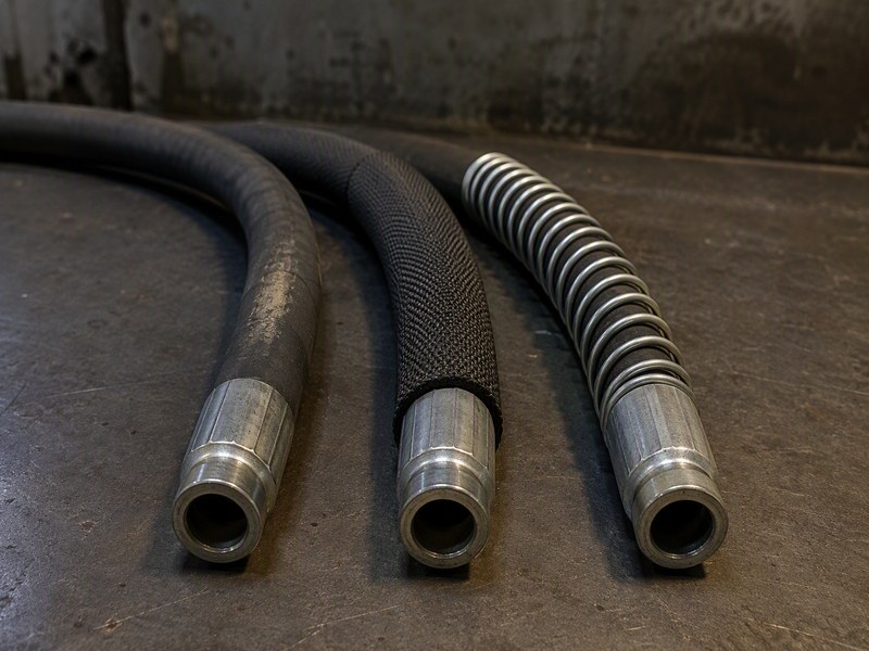
Figure 3. Protection options at a contact point: an unprotected run with a worn cover, a fabric sleeve for broad contact, and a spring guard for a fixed bracket transition.
Clamp tension is the step where protection is most often undone. A clamp that is too loose lets the hose chafe against the clamp itself and against its neighbour. A clamp that is too tight deforms the cover and reduces flexibility at exactly the point where flex is greatest. The right setting holds the hose firmly enough to stop movement and leaves the cover undistorted.
The mechanics of hose support and the routing mistakes that cause premature failure are examined in our guide to improper hydraulic hose routing. The sleeve and guard options are compared in the hose protection sleeve selection guide.
8. How Do Cold Starts and Hot Returns Change the Specification?
Heat-resistant construction is a specification input rather than an environmental detail. A hose that is correct in summer can crack during a cold start, and a hose that is correct in a temperate climate can harden on a machine working beside a furnace or a hot engine block.
Standard 100R-series construction hose carries a temperature rating from about -40 degrees Celsius to +100 degrees Celsius, which is the band published for those constructions, with special grades extending either end of it. Within that range the behaviour changes smoothly, but outside it the failure is fast:
- Below the cold limit. The inner tube and cover stiffen, and the hose becomes prone to kinking and cover cracking at the pivot during the first cycles.
- Above the hot limit. The inner tube hardens and cracks, the cover compound degrades, and the reduction in tube flexibility shortens impulse life.
- Rapid cycling between the two. Thermal cycling ages the tube faster than a steady high temperature, because the elastomer is being worked in both directions.
Cold-weather specification has two parts. The first is a construction rated for the coldest temperature the machine will see, not the average winter temperature. The second is an operating practice: allow the machine to circulate oil and warm the system before applying full load, because the highest bending stress a cold hose sees occurs in the first few movements after start-up.
Hot-circuit specification has the same two parts in reverse. Where a hose runs close to an exhaust, a manifold or a hot hydraulic component, the answer is usually to shield or re-route rather than to buy a higher-temperature hose. Shielding removes the heat from the hose entirely, while a higher rating only moves the limit.
Where the fluid itself is hot, the choice of inner tube compound becomes the governing factor, and it is covered in our fluid compatibility guide. Hoses specified for the extremes of both ends, with the standard families that carry them, are compared in the extreme temperature sourcing guide.
9. How Often Should a Construction Fleet Replace Hydraulic Hoses?
On the moderate and heavy duty groups in Table 8, a hydraulic hose for construction equipment should be visually inspected every 250 operating hours. Machines on rock, demolition, hammer or breaker duty take the shortest interval in that table, and machines on light utility duty take the longest. Replace it when it shows one of the defined rejection conditions, or when it reaches its calendar age limit regardless of appearance. Set the interval from both hours and duty severity, because a hose on a machine working rock and demolition wears several times faster than the same hose on a machine loading sand.
The 250-hour checkpoint is short enough to catch abrasion and fitting weep before they become failures, and long enough to fit into a normal service schedule. It costs a few minutes per machine and it is the single most effective control in the programme.
The rejection conditions below are the ones that justify replacement rather than continued monitoring:
- Cover worn through to the reinforcement. The protective layer is gone and corrosion has started.
- Cracks or crazing across the cover. Ozone and ultraviolet damage has consumed the cover’s protection.
- Bulges or soft spots along the length. Reinforcement separation has begun and a burst is close.
- Kinks, flat spots or a collapsed section. The bend radius has been violated or the tube has failed internally.
- Weeping or a damp ring at the ferrule. The crimp is losing its seal and will fail under load.
- Corrosion or cracking at the coupling. The connection itself is weakening.
- Stiff or hardened hose body. The tube has aged out even though the outside looks sound.
- Reaching the calendar age limit. Manufacturer service-life guidance for this class of hose commonly sits at 5-10 years, and the practical replacement window under normal construction duty is 3-7 years.
Two of the eight rejection conditions above behave differently from the rest and deserve a lower threshold. Abrasion and cover cracking both progress predictably, so they can be monitored at the 250-hour check and replaced at a planned stop. A bulge, a kink or a ferrule weep is a failure in progress and is replaced immediately. Hydraulic oil at construction pressures is a cutting medium rather than a lubricant. Any inspection for leaks is therefore done with the system depressurised, holding a piece of cardboard or wood in front of the joint. A jet is then discovered by a sheet of board rather than by a hand.
Wear rate is not uniform across a machine, which is why a single fleet-wide interval is only a starting point. On a hydraulic hose for excavator duty, the boom and stick lines on the pressure side almost always reach the rejection threshold first. On a mini excavator hydraulic hose the bucket linkage run is usually the earliest casualty. Our full inspection checklist sets out the sequence for a complete machine walk-round, and the routines that keep a programme running across a fleet are covered in the preventive maintenance guide.
A hydraulic hose abrasion protection programme is what turns a 250-hour interval from a discovery exercise into a planning exercise. When the contact points are already sleeved and the clamps are already correct, the inspection usually confirms condition instead of reporting a new failure.
10. What Drives the Cost of a Construction Equipment Hydraulic Hose?
A construction equipment hydraulic hose assembly is a small share of the cost of the failure it prevents. A single pressure line is priced by size and length. A full boom and stick set on a 20-ton machine costs more than any single line on it. A machine sitting idle usually costs more per day than the set of assemblies it is waiting for. Pricing moves with specification, volume and purchase route, so confirm current pricing against the sizes and volumes you order.
Cost per line is set by five factors, and only one of them is the price of the hose:
- Size and length. Larger dash numbers and longer runs cost more per foot, and boom lines are the longest hoses on the machine.
- Fitting type and count. ORFS and metric DIN fittings cost more than JIC, and every 90 degree elbow adds material and crimping labour.
- OEM versus aftermarket. Branded assemblies carrying a machine maker’s part number sit at the top of the price range, while an equivalent aftermarket assembly built to the same standard sits below it, and that ordering usually holds across the volumes a fleet buys.
- Crimping route. A local shop charges per crimp; a factory order spreads the crimping cost across the batch.
- Volume and standardisation. Buying a small number of part numbers in larger quantities reduces unit cost and freight, which is why standardisation pays twice.
A higher hydraulic hose pressure rating bought as insurance is not free insurance. Stepping up a construction class raises stiffness, raises weight, enlarges the bend radius and reduces flexibility at the pivot, so an over-specified line can fail earlier through flex fatigue even though its pressure margin improved. Specify to the circuit, not above it, and spend the difference on abrasion protection where the wear actually occurs.
For a fleet buyer the useful figure is the cost per machine per year rather than the price of one line. That is why hydraulic hose for construction equipment is best budgeted as a consumable item with a planned replacement spend, rather than as a capital spare held against failure.
Three sourcing routes exist and each has a different cost profile. The OEM dealer offers exact fit at the highest price and the longest wait. The local shop offers custom crimping at a moderate price and often same-day service. A manufacturer supplying pre-crimped assemblies offers the lowest unit cost and consistent quality with short bulk lead times. That is usually the right route for planned replacement, and for hydraulic hose for heavy equipment where several identical lines are needed at once. For a single emergency line the local shop is still the fastest answer.
The honest trade-off between the routes is traceability. An OEM assembly traces to the machine builder’s specification, while an aftermarket assembly matches it only when the printed standard and pressure rating line up with the original.
11. How Do Fleets Standardise Construction Machinery Hydraulic Hose and Cut Downtime?
Standardising construction machinery hydraulic hose across a fleet is the single largest cost reduction available to a maintenance department, because it attacks inventory, ordering errors and downtime at the same time. Consolidating overlapping specifications cuts the number of part numbers a fleet carries while keeping full application coverage. In a working hose range, a small share of the part numbers normally carries most of the demand. The size of that effect depends on the fleet, so treat it as a planning assumption rather than a guarantee.
The mechanism is straightforward. Every extra part number has to be forecast, stocked, found in the warehouse and re-ordered, and each one carries a chance of being the wrong thread for the machine in front of the technician. Removing the redundant ones reduces all of those costs at once.
A workable standardisation programme has four moving parts:
- One construction class per machine family. Lock in the reinforcement family each weight class uses, so a technician reaches for the same hose on every machine of that class.
- One fitting standard per machine family. Metric DIN for Komatsu and Chinese compact machines, JIC or ORFS for American and Japanese models, recorded against the machine rather than left to memory.
- A fixed dash-size list. Stock only the sizes the fleet genuinely uses, and eliminate the ones that move a few units a year.
- Pre-crimped, pressure-tested assemblies. Ordering finished assemblies removes crimp-quality variation between sites and removes the temptation to reuse a ferrule.
The comparison below is the shape of the change on a typical multi-brand construction fleet.
Table 6. A typical multi-brand construction fleet before and after hose standardisation, showing where the savings come from
| Specification area | Before consolidation | After consolidation | Source of the saving |
|---|---|---|---|
| Working pressure classes | Five overlapping classes | Two classes per machine family | Fewer part numbers to forecast and stock |
| Dash sizes stocked | Every size the fleet ever bought | The sizes the fleet actually uses | Lower inventory value, faster picking |
| Fitting standards | Mixed, with adapters used to bridge them | One standard recorded per machine family | Fewer ordering errors and repeat leaks |
| Assembly source | Crimped on site, quality varies by technician | Pre-crimped and pressure-tested in batches | Consistent crimp performance, fewer comebacks |
| Purchase pattern | Small frequent orders across many suppliers | Larger scheduled orders with fewer suppliers | Better unit price and lower freight per assembly |
| Protection hardware | Fitted after a failure | Sleeves and guards on all known contact points | Fewer abrasion failures, fewer unplanned stops |
Two cautions belong with Table 6. Eliminating part numbers without checking what the machines actually run creates stockouts, because demand shifts onto the remaining items and the reorder points were set for the old pattern. And over-standardising removes the specialised hoses that serve high-margin or unusual work, such as a high-temperature line on a machine that works beside a kiln. The sensible rule is to standardise everything that repeats and to keep, as a documented special, anything that solves a problem the standard line will not.
Writing the decision down is what makes it stick. A fleet hydraulic hose selection guide is one or two pages recording those same decisions machine family by machine family, plus the protection each one needs. It turns a set of tribal answers into a document a new technician can follow. The broader method behind those choices is set out in our guide to the STAMPED selection method (Size, Temperature, Application, Media, Pressure, Ends, Delivery) and in our hydraulic hose standards overview. The finished assemblies, together with the consolidated part numbers that make volume pricing possible, are listed in our construction hose range.
12. Which Hydraulic Hose Does Each Circuit on a Construction Machine Use?
A hydraulic hose for construction equipment is not one specification repeated around the machine. Each circuit has a different pressure band, a different flow requirement and a different exposure to abrasion, so a machine carries several distinct assemblies that happen to look similar.
Working circuit by circuit is the fastest way to specify a replacement set, and it is also the way to work out which lines deserve a protection sleeve and which ones can be left bare.
The table below maps the circuits on a typical mobile machine to the size and construction each one normally needs.
Table 7. Circuits on a construction machine, the sizing and pressure band each works in, and the construction normally fitted
| Circuit | Function | Typical size and form | Typical pressure band | Exposure to damage |
|---|---|---|---|---|
| Travel motors | Drives the tracks or wheels through the final drive | Dash 12 to dash 20; long runs from the swivel joint (centre joint) | High, near relief setting | Underside runs exposed to ground contact and debris |
| Boom and stick cylinders | Raise, lower and extend the working structure | Dash 8 to dash 16; straight runs along the boom | Highest on the machine | Rod and boom contact, pivot flex, UV on long straight runs |
| Bucket cylinder | Curls and dumps the attachment | Dash 6 to dash 12; short assemblies with elbows | High, with shock on contact | Closest to the digging end, so debris and impact |
| Swing and turret circuits (upper structure) | Rotates the upper structure | Dash 8 to dash 12; routed through the centre joint | Moderate to high | Routing congestion inside the turret |
| Blade, ripper and stabiliser | Operates the dozer blade, ripper or outrigger stabilisers | Dash 8 to dash 16; often exposed to the ground | Moderate to high | Ground contact and impact |
| Loader lift and tilt | Raises and levels the bucket or forks | Dash 8 to dash 16; long runs along the lift arm | High | Linkage contact points |
| Attachment and auxiliary circuits | Feeds a breaker, thumb, grapple, shear or tiltrotator | Dash 6 to dash 12; often quick-coupler terminated | High and strongly cyclical | Quick-coupler joints, plus hose left hanging at the end of the stick |
| Pilot and control circuits | Carries control pressure to the valve spools | Dash 4 to dash 6; many short assemblies in the cab circuit | Low, typically under 600 PSI | Cab entry points and abrasion against the harness |
| Return and case drain | Returns oil to tank and drains motor or pump cases | Dash 12 to dash 24; the largest bore on the machine | Low, and sensitive to back pressure | Long runs down the boom and around the frame |
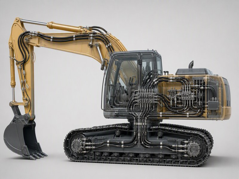
Figure 4. Circuit map for a tracked machine: travel lines run from the swivel joint, working lines run along the boom, and the largest bore on the machine is a low-pressure return.
Two observations follow from Table 7. The largest bore on the machine belongs to a low-pressure return line, so sizing purely by pressure produces oversized and heavy return runs. And the circuits exposed to the most mechanical damage are the ones at the digging end and the underside, which is where protection hardware earns its cost.
Circuit identity also explains a pattern seen in fleet records. The pressure-side boom and stick runs on a hydraulic hose for excavator duty reach their replacement threshold well before the pilot and return circuits on the same machine get close. On a mini excavator hydraulic hose the bucket-cylinder assembly is usually the first casualty of a season, because it sees shock load on every bucketful as well as the tightest bend of any line on the machine.
13. How Do You Commission a New Hydraulic Hose for Construction Equipment on Site?
Fitting a new hydraulic hose for construction equipment is only half the job. An assembly that was built correctly can still be installed in a way that shortens its life or introduces contamination, and commissioning is where both are caught.
The sequence below takes about half an hour for a single line and considerably less for a planned set.
- Confirm the assembly before it goes on. Check the dash number, the printed standard and the pressure rating against the machine’s requirement, and check the end angles against the original.
- Cap and plug until the moment of connection. Remove the protective caps only when the fitting is about to be made, so the interior stays clean.
- Clean the port and the fitting. Wipe both faces, inspect for damaged threads, and replace the O-ring on ORFS and DIN connections rather than reusing it.
- Start the thread by hand. A fitting that will not turn by hand for the first turns is cross-threaded, and continuing with a wrench damages the port.
- Torque to the published figure. Flare and face-seal connections seal metal to metal or against an O-ring, so a torque figure matters more than tightness by feel.
- Restore the routing, not just the connection. Re-fit the clamps at their original positions and reinstate the slack at every pivot, so the hose flexes in an arc rather than a straight line.
- Verify the hydraulic hose pressure rating expectation against the relief setting. Confirm on the machine that the relief valve is set where the documentation says it is, because a hose selected for the wrong setting is the most expensive kind of correct-looking mistake.
- Cycle the function and inspect under motion. Run the machine through several full cycles, watch the hose at the pivot while it moves, and check every joint for weeping afterwards.
Watching a hose under motion is how a routing problem is found before it becomes a wear problem, and it takes a minute per line. Make that check a written step in the procedure rather than a habit.
14. How Do You Keep Contamination Out When Changing Hose in the Field?
Dirt entering the circuit during a hose change is the leading cause of premature pump and valve wear afterwards, and field conditions on a construction site are the worst possible environment for the job. The contamination is introduced by the work, not by the hose.
The controls below are the ones that matter most, and they cost almost nothing to apply:
- Cap every open end immediately. A disconnected port left open for the length of a lunch break has collected enough dust to matter.
- Plug the new assembly until installation. A pre-crimped assembly that was shipped with caps and stored with them still fitted arrives clean.
- Work on a cleaned area where possible. Wiping the port before opening it stops surface dirt from dropping into the circuit.
- Filter any fluid added during the job. Top-up fluid from an open container carries both particles and water.
- Flush a hose that was cut or crimped on site. A site-crimped assembly carries debris from the cutting and crimping process.
- Record the change in the machine’s hose register. The next technician needs to know which line was replaced and when.
This is one of the reasons a fleet hydraulic hose selection guide pays for itself. When the replacement is a pre-crimped assembly ordered against a recorded part number, the technician is fitting a proven component rather than cutting and crimping one in a dusty yard. The same discipline is what makes hydraulic hose abrasion protection worth fitting: a sleeved hose has to be removed less often, and every removal is a contamination opportunity.
15. What Changes for High-Impulse Attachments Such as Breakers and Grapples?
Hydraulic breakers, grapples, shears and thumbs are the hardest duty cycle a construction machinery hydraulic hose can face. They combine high pressure with a rapid, repeated cycle, and the hose run hangs exposed at the end of the machine.
Impulse life is the property that decides how a hose behaves here. The impulse test is the single best predictor of service life on a breaker circuit, because a breaker swings the line from low to high pressure on every blow. A hose that only meets a baseline impulse requirement may not last as many cycles as a premium construction.
The specification changes that follow from that duty:
- Move up an impulse grade. The requirement is cycle life, and a higher pressure rating alone does not deliver it, so pressure class and impulse grade are two separate decisions.
- Keep the line short and supported. A long unsupported run at the end of a stick whips and fatigues; shortening the run and supporting it at intervals does more than any change to the hose.
- Guard the hanging section. The exposed run between the quick coupler and the attachment is the most vulnerable hose on the machine.
- Check the quick-coupler joint as part of the routine inspection. Coupler seals degrade faster under cyclical pressure than a crimped ferrule does.
- Expect a shorter replacement interval. On hydraulic hose for heavy equipment working breaker duty, the attachment feed lines are replaced several times more often than the boom lines on the same machine.
16. How Do You Build a Replacement Schedule for a Mixed Fleet?
A replacement schedule turns hose maintenance from a reaction into a plan, and it is the step most fleets take last. It matters because the cost of a hose is small and the cost of the downtime it causes is large. The objective is not to minimise hose spend, but to move replacements to a time when the machine is not needed.
The schedule below is built from four inputs that a maintenance department already has:
- Machine register with utilisation hours. Split the fleet by annual hours, because a machine working two shifts wears hoses several times faster than one working one shift.
- Application severity. Group machines by what they work: rock, demolition and trenching wear hoses faster than bulk loading and lifting.
- Known high-wear circuits. Use the circuit map from section 12 to pre-identify the lines that fail first on each platform.
- Recorded replacement history. Every recorded change sharpens the interval estimate, which is why recording the change matters as much as making it.
The table below shows how those inputs translate into a workable interval structure.
Table 8. A worked replacement-schedule structure for a mixed construction fleet, by duty severity rather than by machine model
| Duty group | Typical work | Visual inspection interval | Planned replacement point | Lines replaced most often |
|---|---|---|---|---|
| Severe | Demolition, rock trenching, hammer and breaker work | Every 100-150 hours on high-wear circuits | Planned set at 3-4 years | Attachment feed lines, bucket cylinder lines |
| Heavy | Mass excavation, quarry loading, site clearance | Every 250 hours | Planned set at 4-6 years | Boom and stick lines, travel lines |
| Moderate | General earthmoving, grading, trenching in soft ground | Every 250-500 hours | Planned set at 6-8 years | Boom lines, loader lift lines |
| Light | Lifting, handling, utility work, low-cycle duty | Every 500 hours | Planned set at 8-10 years, subject to the age limit | Return and pilot lines |
The schedule is a starting structure, not a fixed rule, and it should be adjusted by what the records show. The value of writing it down is that it converts an unplanned failure into a planned stop, and it tells the purchasing side in advance which part numbers to hold.
Two administrative pieces make the schedule work in practice. The first is a part-number list per machine family, which is the fleet hydraulic hose selection guide described in section 11. The second is a minimum stock holding of the highest-wear lines, so a failure on a hydraulic hose for excavator duty is answered from the store rather than from a supplier’s lead time. Keeping a small stock of the lines that fail most often, plus sleeves for the contact points, is a modest inventory investment that removes the most common reason a machine sits idle.
17. Frequently Asked Questions
What hydraulic hose does a construction machine need?
Match the working pressure to the machine’s relief valve setting, then choose the reinforcement construction and the fitting thread for that circuit. Compact and mid-size machines normally run two-wire braid to SAE 100R2 or EN 853 2SN, and machines above roughly 30 tons run four-spiral construction to EN 856 4SP or 4SH.
How do I know which hydraulic hose for excavator boom lines to order?
Read the marking printed on the old cover first, because it carries the dash number, the standard and the working pressure. Confirm the bore with a caliper and identify the thread with a gauge, then order by the distance between the fitting seal faces, since end angles make overall length unreliable.
What do I need to check on a mini excavator hydraulic hose?
Check the thread family first. Most Chinese and Japanese compact machines use metric DIN 2353 24 degree cone fittings in M14x1.5 or M16x1.5, which need an adapter if the replacement carries a SAE JIC end. Then check the elbow angle at the cylinder end, because a different angle changes the routing at the pivot.
Is one construction class enough for all hydraulic hose for heavy equipment?
Two classes usually cover a mixed fleet. Two-wire braid handles the pressure lines on compact and mid-size machines, and four-spiral handles large and mining-class machines. A fleet that stocks both covers the pressure range without carrying a third family that rarely gets used.
Should a mixed fleet adopt one hydraulic hose selection guide?
Yes, as a one or two page document recording each machine family’s construction class, thread standard, dash sizes and protection requirements. Consolidation only holds while it is written down: without the guide the part numbers drift back as machines change hands. The saving it protects is real but fleet-specific, so treat it as a planning assumption rather than a guarantee.
What hydraulic hose pressure rating covers most construction circuits?
Two-wire braid rated for 3,000 to 5,000 PSI covers the pressure lines on most compact and mid-size construction machines. Four-spiral rated for 4,000 to 5,800 PSI covers large excavators and high-impulse circuits. On machines with a relief setting close to the top of a class, move up one class rather than accepting a thin margin.
How long does a construction equipment hydraulic hose last?
Plan on a working life measured in years rather than in hours alone. Two limits run in parallel: a 5-10 year service-life band, and a shorter 3-7 year replacement window in ordinary construction work. Heat and oil exposure age the inner tube even when the cover still looks sound, so calendar age carries as much weight as the hour meter. Machines on rock, demolition or abrasive ground sit at the short end of that window.
What should I do when a construction hydraulic hose is leaking at the fitting?
Stop the machine, release the pressure and only then touch the joint. A ferrule that is weeping or shows a damp ring has already lost its seal, and it is replaced rather than retightened. Fit a new O-ring on ORFS and DIN connections instead of reusing the old one. Check the thread family against the port as well, because a mismatched thread leaks again at the same joint.
Can I fit a protection sleeve over a hose that is already worn?
A sleeve slows further abrasion at a contact point. Applies to: a hose whose cover is still intact. Does not apply to: a hose already worn through to the reinforcement, because a sleeve adds no cover material back and hides the damage from inspection. For that hose the order is to replace the hose first, then fit the sleeve to the new assembly.
Do I need a higher pressure rating for a cold-weather machine?
No. Cold changes the flexibility requirement rather than the pressure requirement. What changes is the construction: specify a hose rated for the coldest temperature the machine will actually see, and let the system circulate oil before full load so the first movements after start-up do not bend a stiff cover.
Should I use OEM or aftermarket hose assemblies?
An aftermarket assembly matches an OEM assembly when it carries the same standard and the same printed working pressure rating. It is usually the cheaper of the two routes, though the size of the difference is specific to the part and the order. The trade-off is traceability: OEM assemblies trace to the machine builder’s specification, and aftermarket assemblies match it only when the printed numbers line up.
What is the most common ordering mistake on construction hose?
Getting the fitting thread wrong. A thread that does not match the port is usually discovered at installation, when the machine is already apart. Gauge the port and record the family against the machine before ordering, so the assembly arrives with the end it needs.
Does a hydraulic hose for construction equipment need pressure testing before installation?
A hose that was assembled on site should be proof-tested before it goes into service, and an assembly bought from a manufacturer should already have been tested at the factory. Proof pressure is normally about twice the working pressure, so it verifies the crimp rather than the hose, which is where assembly faults concentrate.
Which thread family does a skid steer loader use?
Current skid steer loaders are usually built with ORFS face-seal fittings on their lift, tilt and auxiliary circuits, while older machines in the same class often use JIC 37 degree flare. Confirm with a thread gauge before ordering, because both families appear on machines that are still in daily service.
How do I build a spare-hose kit for a construction machine?
Stock the lines that fail most often on each platform rather than one of every size, and hold them pre-crimped and capped. Table 7 identifies the boom, stick, bucket and attachment feed lines as the highest-wear assemblies on most machines. A small stock of those lines removes the lead time from the most common breakdown.
I run a five-machine mini excavator hire fleet. Which hose sizes should I stock?
Work from Table 1 and Table 3 rather than from a full size range. A fleet of 1-3.5 ton machines normally runs dash 6, dash 8 and dash 4 pilot lines on two-wire braid, with the bucket linkage run the first casualty. Hold those sizes pre-crimped and fit sleeves at the contact points.
I have just bought a 20-ton excavator and work through cold winters. What changes in the specification?
The fitting standard does not change, and the pressure class moves only where the arithmetic in section 4 pushes the relief setting past the top of the band. The cold-start requirement is settled by the construction choice and warm-up practice in section 8. A 20-ton machine sits in the mid-size band in Table 1, and two-wire braid covers it while the 25% margin holds.
18. Sourcing Construction and Excavator Hydraulic Hose
Every specification decision in sections 1 to 16 ends in the same place: an assembly that either matches the machine or does not. HENGHUA manufactures hydraulic hose for construction equipment and excavator applications, and supplies it as pre-crimped, pressure-tested assemblies rather than as loose hose and separate fittings.
Three things about how we work are worth knowing before you send a request, because they are the parts that usually decide whether a replacement programme runs smoothly:
- Application-matched construction. We build two-wire braid to SAE 100R2 and EN 853 2SN for compact and mid-size machines, four-spiral to EN 856 4SP and 4SH for large excavators and concrete pump booms, and heavy spiral for mining-class circuits.
- Termination built to the machine, not to a catalogue default. JIC, ORFS, BSP, NPT and metric DIN 2353 ends are crimped to the thread family your machine actually uses, so the assembly arrives without adapters.
- Assemblies proven before shipment. Every assembly is crimped in-house and pressure-tested, so the line you install has already held pressure at the factory rather than for the first time on your machine.
We work with owner-operators replacing a single boom line and with fleets standardising hose across a mixed machine population. For fleet enquiries we can align a standardisation list to your machine register, hold agreed dash sizes and thread standards as repeatable part numbers, and quote against a scheduled replacement programme rather than single orders.
Send us your machine model, a photograph of the hose marking and the fitting thread, and the centre-to-centre length, and our engineering team will confirm the specification and quote matched assemblies. If you are planning a fleet programme instead, send your machine list and we will come back with a consolidated part-number schedule. Both routes reach the same engineering desk, through our construction hose range or the contact form.
About the author. This guide was prepared by the HENGHUA hydraulic applications engineering team. The team works daily with machine registers covering Komatsu, Hitachi, Caterpillar, Volvo and Chinese compact excavator platforms, and supports construction, mining and agricultural equipment owners with hose specification, assembly design and fleet standardisation.
 English
  Spanish
  Portuguese
  French
  German
  Arabic
  Russian
  Indonesian
  Japanese
  Korean