
Dock hose selection comes down to five variables. Those variables are bore, working pressure against the relief setting plus static head, string length and geometry, end fittings, and the inspection regime the berth can actually sustain. Get those five right and the hose survives the marine environment. Get one wrong and the failure appears at the manifold, usually at night.
This guide works through each variable in the order a terminal engineer meets it. It covers how bore affects loading time. It explains why the pressure figure must be built from the relief valve and the static head rather than copied from a catalogue. It also sets out how to lay out a string over a tide range, and what the inspection cycle has to include to keep a berth in service.
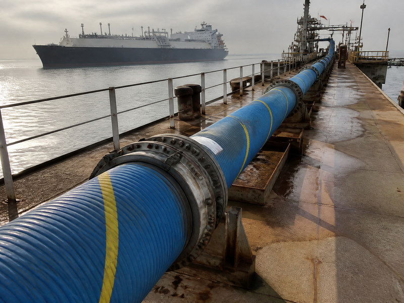
Figure 1. The string is clear of the deck, and the arm is connected at the far end.
What Does a Dock Hose Have to Do?
It has to move product between a fixed manifold and a vessel that moves. That single sentence explains most of the requirements that follow.
The vessel rises and falls with the tide, shifts along the berth with wind and current, and changes list as tanks fill. The hose has to absorb all of that movement without being pulled into tension and without being pushed into a kink. It also has to survive salt spray, ultraviolet light, ozone from electrical equipment and the abrasion of a concrete apron.
A dock hose is therefore a handling item as much as a pressure item. A hose that meets every pressure requirement and cannot be rigged by two people will be dragged, and a dragged hose has a short life regardless of its construction.
What Sets the Bore?
Flow rate and the time the berth can afford, in that order.
Bore sets the loading time, and the 6 inch line is the usual compromise for a berth that has to be rigged by hand. The flow figures for each bore sit in our sizing guide. A 4 inch line is a third of the 6 inch figure, which is why 4 inch is used for lubricants and small parcels rather than for cargo.
The berth economics decide the rest. A larger bore shortens the pumping time but adds weight, and a dock hose is handled by hand or by a small crane at every connection. The full arithmetic, including pressure drop and the point where the fixed connection time dominates, sits in that guide.
Three practical notes narrow the choice further. Very large bore needs a saddle or a hose crane at the berth, which not every terminal has. Product holdup in a big bore is lost or displaced at every transfer. And the bend radius grows with bore, so a berth built around a 4 inch line may not have room for the 8 inch radius.
What Working Pressure Should a Marine Dock Hose Carry?
On a marine dock hose the figure comes from the system, not from the hose catalogue. Start with the relief valve setting, add the static head at the point where the hose is installed, and require a maximum allowable working pressure above that sum.
On a US berth the figure comes from the relief valve setting plus static head, and the clause that fixes the arithmetic is covered in our walkthrough of the hose clause. A 10 bar relief setting with 2 m of static head points at a 14 bar type, and the reason is in that guide rather than in the hose catalogue.
The composite type table gives four working pressures: 4 bar for Type 1, 10 bar for Type 2, and 14 bar for Types 3 and 4. The proof pressures are 6, 15, 21 and 21 bar, and the minimum burst pressures are 16, 40, 56 and 56 bar. Those are the figures to quote in a tender, because they can be checked against the design calculation without asking the supplier to confirm anything.
Two exceptions matter on a jetty. A vapour return line runs at low pressure but needs a vacuum rating. A Type 1 hose at 0.5 bar vacuum may be the wrong choice if the line is also used for suction. And a line that is blanked at both ends with product inside can see a pressure rise from thermal expansion, which the relief arrangement has to handle rather than the hose.
How Long Should the String Be?
Long enough to reach the ship manifold at the lowest tide with the vessel at its furthest drift, and no longer.
Excess length is a defect, not a margin. A string with slack forms a low point, and a low point holds product when the line is drained. That product either becomes a spill risk at disconnect or a slow internal attack on the lining. Slack also loops near the deck, where a vehicle or a fitting can catch it.
Too little length is worse. A hose pulled into tension at high tide loads the fittings in a direction they were not designed for, and the ferrule is where that load shows first.
The working method is to plot the geometry. Take the manifold height, the ship connection height at light and loaded draft, the tide range, and the horizontal travel from the drift allowance. The difference between the longest and shortest distance is the movement the string has to absorb, and the hose route has to absorb it in a bend rather than in tension.

Figure 2. The string runs the length of the jetty on steel cradles, with the bollard and the water alongside: it is supported clear of the deck for the whole run. Length and support are covered below, and the working pressure is in Table 1.
What About Support Along the String?
Support keeps the hose off the deck and stops the bend from forming where the string meets the manifold. The spacing is an engineering decision rather than a standard figure, and it depends on the bore, the mass of the filled hose and the bend radius.
Three rules are worth keeping regardless of the numbers.
- Support at the change of direction, so the bend is held rather than hanging.
- Never support on a sharp edge, a pipe stub or a handrail, because a point load on a fabric cover becomes a hole.
- Leave the string free to move at the vessel end, so tide movement is taken in the bend and not in the supports.
A saddle that is too narrow does more harm than no saddle, because it concentrates the load on one line of the cover and wears through the coating first.
Which End Fittings Belong on a Jetty Hose?
The usual arrangement is a fixed flange at the shore end and a floating flange at the ship end. The fixed flange takes the load and the floating flange rotates so the bolt holes line up without twisting the hose.
A jetty hose with a floating flange is easier to connect in a swell, because the bolt holes can be rotated into line while the string hangs free. Flange drilling matters. A terminal working to ANSI B16.5 will not accept a flange drilled to another pattern, and the mismatch is usually discovered during the first connection rather than at the drawing stage.
Flange drilling has two families in common use, and they are not interchangeable even when the bolt circle looks close. Class ratings and PN ratings come from different standards and carry different pressure-temperature curves, so the order should name the standard, the size, the facing and the rating, not just “150 lb”. The glossary carries the term as it is used on a datasheet. Quick-disconnect couplings are used on smaller lines, and they need the same attention to the bore through the coupling, which is often smaller than the hose.
Three details are worth writing into the order. Lifting eyes or a sling point, so the assembly is lifted by its fittings rather than by the hose body. Blank caps and gaskets supplied with the assembly, so a spare hose is usable at once. And a marking band near each end carrying the working pressure, the bore and the test date, so the pre-transfer check has something to read.
Why Does a Dock Hose Fail?
Six causes account for most of the withdrawals we see at berths.
- Cover chafe at a saddle or a deck edge, which exposes the fabric and then the helix.
- A kink at the manifold, caused by a string that is too short at low tide.
- Corrosion at the ferrule, where salt water sits in the gap between hose and fitting.
- Fatigue at a fixed bend, where the hose is supported so rigidly that all the movement goes into one section.
- Crush by a vehicle or a dropped fitting, which flattens the helix.
- Ozone and ultraviolet cracking on a cover that is stored in the open.
Only the first two are visible in a photograph. The others need a hand on the hose and a light on the fittings.
What Inspection Keeps a Berth in Service?
The cycle has three layers, and each one catches a different stage of deterioration.
| 레이어 | What is checked | Frequency in practice |
|---|---|---|
| Pre-transfer | Cover condition, kinks, bulges, soft spots, fittings, marking legible, bend radius respected | Before every transfer |
| Scheduled walk-round | Full length inspection, ferrule condition, support condition, cover chafe points | Monthly, or per the facility procedure |
| Pressure test | Proof test of the assembly at the specified figure, with a record | Annually, or as the facility and regulator require |
Table 1. Inspection layers for a dock hose. The pre-transfer check is the one that stops a transfer, so it has to be quick enough to be done properly every time.
The pressure test figure for a US terminal is 1.5 times the maximum allowable working pressure, held as a static liquid test, with the whole external surface accessible during the test. The same rule sets the retirement criteria: no unrepaired loose covers, kinks, bulges or soft spots, and no gouges or cuts that reach the first reinforcement layer.
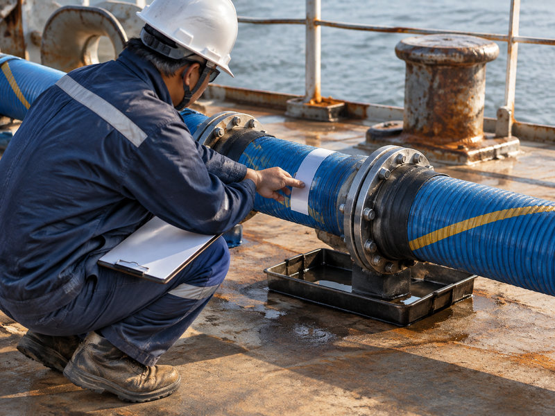
Figure 3. A checker at the joint with a clipboard and a tray under it: the pre-transfer check happens here, at the connection, not in the office. What is checked at each interval is in Table 2, and the retirement points are listed above.
Which Duties Suit Which Construction?
| 의무 | Usual bore | Working pressure class | Construction note |
|---|---|---|---|
| Crude and product bunkering | 6 to 8 inch | 14 bar type | Large bore, floating flange at the ship end |
| Chemical parcel transfer | 4 to 6 inch | 10 to 14 bar type | Lining chosen per product list |
| Vapour return | 3 to 6 inch | 4 bar type | Needs a vacuum rating, not just pressure |
| Lubricating oil and small parcels | 3 to 4 inch | 10 bar type | Small bore, camlock or flange |
| Ship to shore with high tide range | 6 to 8 inch | 14 bar type | Length and support decide the layout |
Table 2. Dock hose duties against bore, pressure class and construction note. The vapour case is the one most often specified as a liquid line and then found to need a vacuum rating.
What Does a composite dock hose Offer?
A composite dock hose brings three things to a berth: low mass at large bore, a bore that stays round under vacuum, and a wall that tends to leak before it bursts.
The mass matters because it changes the rigging. A 6 inch composite hose can be handled by two people on a dry run, which shortens the connection time and makes the pre-transfer check easier to do properly. The vacuum rating matters on a berth that also pulls suction or returns vapour. The failure behaviour matters because a leak at a jetty is a cleanup while a burst is an incident.
Against that, a composite dock hose is not the answer for every berth. A line that sees steam, or a hot product above +150 °C, needs a different construction. A berth with a very tight bend at the manifold may need a metal hose to fit the geometry. And a berth that handles abrasive slurry will wear any thin-wall hose out quickly.
What the composite construction does well is the ordinary cargo transfer that most terminals run, at 10 to 14 bar and ambient to moderate temperature, with a crew rigging the line by hand.
Which Documents Should Accompany the Hose?
A berth audit asks for paperwork as often as it asks about the hose itself.
- A test record for the assembly, with the pressure applied and the date.
- A marking check, showing the working pressure, bore, product service and test date on the hose.
- The burst figure for the type, traceable to the standard rather than to a brochure.
- The liner material, so a product change can be assessed without guessing.
- The date of manufacture, which sets the review point for the assembly.
For US terminals the marking and record requirements come from the hose rules in 33 CFR 154.500, which our clause guide works through line by line. For berths outside the US, the same information is usually requested by the terminal operator and the surveyor, even where no rule compels it.
자주 묻는 질문
What is a dock hose?
A dock hose is a flexible transfer line used between a terminal manifold and a vessel at a berth. It is built for large bore, moderate pressure and repeated handling in a salt-water environment.
How do I choose the bore?
From the cargo size and the time the berth can spare, at a velocity of 2 to 3 metres per second. A 6 inch line suits most bunkering and parcel work, and an 8 inch line is chosen when the berth time is the constraint.
What pressure should a marine dock hose be rated for?
Above the relief valve setting plus the static head at the hose, with a design burst of at least four times that sum. Most terminal duties land on a 14 bar type in the composite standard.
Should the hose be longer than the distance between manifolds?
No, unless the tide and drift require it. Length should cover the largest distance the vessel can reach, and no more, because slack creates a low point that holds product.
Which end fittings are usual?
A fixed flange at the shore end and a floating flange at the ship end, drilled to ANSI B16.5, with lifting points and blank caps. Smaller lines may use quick-disconnect couplings.
How often should a dock hose be tested?
At least annually at most terminals, and always before a transfer after a long lay-up. The pre-transfer check runs before every single transfer regardless of the test date.
Can a jetty hose be repaired?
A cover repair is possible if the fabric is intact. A hose with a damaged helix, a loose cover or a cut into the reinforcement should be retired, because a repair cannot restore the pressure path.
About HENGHUA
HENGHUA builds dock composite hose and hose assemblies in XLPE, UHMWPE, polypropylene and PTFE linings, a woven fabric reinforcement, and a stainless steel or coated carbon steel helix, in bores from 25 mm to 300 mm. Ends are crimped or flanged, with fixed or floating flanges, and lengths are built to the berth geometry rather than to a stock table.
The large bore dock composite hose and the bunkering hose assembly show the current build options, and the ship to shore range covers the floating flange arrangement. The full range sits in the composite hose category. If you are specifying a berth, send the manifold heights, the tide range, the cargo and the relief valve setting, and we will size the string and the pressure class together.

 English
 Spanish
 Portuguese
 French
 German
 Arabic
 Russian
 Indonesian
 Japanese
 Korean