
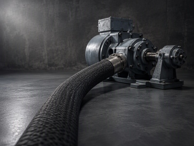
Choose the air hose for air motor duty by matching the motor’s published air consumption — not its horsepower — to a hose bore that keeps pressure drop at or below about 10% of line pressure over your actual run length. In practice that means 3/8-inch bore as the practical minimum for most small vane motors, 1/2-inch for anything consuming more than roughly 20 CFM, and never a 1/4-inch hose beyond 25 feet. Then choose the tube material for the environment and fittings that do not throttle the line.
This guide walks through a six-step method for the air hose for air motor choice, gives a quick-reference table of bore and length against air consumption, and covers the four mistakes that leave air motors running weak.
Choosing the air hose for air motor duty is a sizing exercise, not a shopping exercise. Three questions drive it: how much air the motor consumes, how far the air has to travel, and how much pressure loss the installation can tolerate. Get those three right and a working air hose for air motor installation is determined, along with the fittings that keep it performing. Get them wrong and no hose will deliver the motor’s rated output.
About a 14-minute read at 250 words per minute; rated ranges follow ISO 5774:2023 and ISO 2398:2024.
Why an Air Hose for Air Motor Duty Is Harder to Size Than an Air Tool
Most air tools run intermittently. An air motor often runs continuously — as the drive on a mixer, a winch, a hoist, a conveyor, a filling head, or a pump — and it draws its full rated airflow the entire time it is loaded.
That changes the calculus in two ways:
- Line loss accumulates every second. An undersized hose on an intermittent tool costs a moment of performance. On a continuously running motor it costs torque, speed, and air volume for the whole shift.
- The motor is often the production bottleneck. If the motor stalls, the line stops. Over-sizing the hose is cheap insurance; under-sizing it is a recurring production cost.
A second factor is that air motors are frequently specified at a nominal pressure such as 90 PSI, and their rated power and speed assume they actually receive it. A 10 PSI loss at the inlet is not a 10% inconvenience — for a vane motor it translates into a disproportionate loss of speed and torque.
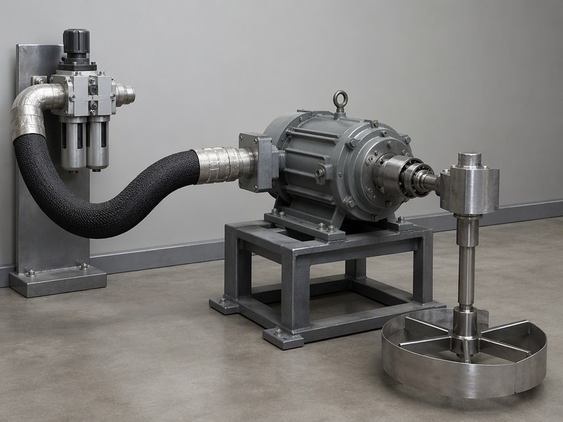
Figure 1. An air motor installation. The hose bore, not the compressor, usually decides whether the motor sees full rated pressure at the inlet.
Step 1: Read the Motor’s Air Consumption, Not Its Horsepower
The air motor air consumption figure, not the horsepower, is what the hose is sized from. Two motors of the same power rating can consume very different air volumes, and motor type decides this:
Table 1. Air motor types and their air-consumption characteristics. Figures are typical orders of magnitude per 1 HP of rated output — always use the motor manufacturer’s data for the unit you are installing.
| Motor type | Typical air consumption | Behavior under load | Hose implication |
|---|---|---|---|
| Vane | Highest per HP | Speed rises with flow; output torque falls with speed | Needs the largest bore of the four |
| Piston | Moderate | More constant torque, pulsing demand | Moderate bore; allow for demand peaks |
| Diaphragm | Moderate to high | Self-priming, low flow tolerance | Moderate bore; avoid long runs |
| Turbine (high speed) | High at high speed | Very high speed, low torque | Large bore; short runs preferred |
Use the air motor air consumption figure from the datasheet, at rated power and rated pressure, in CFM or m³/h. If the datasheet gives only a power rating, ask the motor supplier for the consumption figure — this one number drives everything else in the selection.
Step 2: Set the Acceptable Pressure Drop
The industry rule of thumb is to keep total line loss at or below 10% of the motor’s rated inlet pressure. On a 90 PSI system that is about 9 PSI; on a 6 bar system, about 0.6 bar.
That allowance covers the whole path from the compressor outlet to the motor inlet: the main line, the hose, the fittings, the filter-regulator-lubricator unit, and the quick couplers. If your fixed installation already eats 4 PSI, the hose has about 5 PSI of budget left.
Two implications follow:
- Count the fittings. A 1/4-inch quick coupler on a 3/8-inch line is a throttle. Flow restriction in fittings often exceeds the drop in the hose itself.
- Halve the length allowance for a coil. A coiled hose is a wound restriction; treat its effective loss length as longer than its stretched length.
Step 3: Convert Flow and Length Into Bore Size
Bore size should be chosen from flow and length together, as set out in our air hose size chart, because line loss rises with length and climbs sharply with flow, and falls steeply as bore increases.
Table 2. Planning table: maximum hose length in feet for a line loss of about 9 PSI (10% of a 90 PSI system), smooth-bore hose, straight run, couplings excluded. Use as a starting point and confirm against your motor’s datasheet and pressure-drop data.
| Hose bore | 10 CFM | 20 CFM | 40 CFM | 60 CFM |
|---|---|---|---|---|
| 1/4 in (6 mm) | ~25 ft | ~10 ft | Not suitable | Not suitable |
| 5/16 in (8 mm) | ~45 ft | ~20 ft | Not suitable | Not suitable |
| 3/8 in (10 mm) | ~100 ft | ~40 ft | ~15 ft | Not suitable |
| 1/2 in (13 mm) | 150 ft + | ~100 ft | ~40 ft | ~25 ft |
| 3/4 in (19 mm) | 150 ft + | 150 ft + | ~100 ft | ~60 ft |
Read the table as a warning about 1/4-inch hose rather than a recommendation of 3/4-inch hose. A 1/4-inch hose cannot feed a 40 CFM motor at any useful length, and a 25-foot 1/4-inch hose is already marginal at 10 CFM once fittings are counted.
The same data expressed for 3/8 versus 1/2 inch comes down to two cases. If your run is 40 feet and your motor draws 20 CFM, both bores work: choose 3/8 inch for a mobile or hand-positioned hose, and 1/2 inch for a permanently installed one where the cost difference is small.

Figure 2. Pressure drop against run length at constant flow: the same flow costs several times more loss through 1/4-inch bore than through 1/2-inch, which is why bore is chosen from length as well as consumption.
Step 4: Choose the Air Hose Working Pressure With a Real Margin
Select a hose whose working pressure comfortably exceeds your system pressure, then check the burst rating for the safety factor.
- Textile-reinforced air hose: typically 200–300 PSI working pressure, burst at three to four times that.
- Spiral-reinforced or wire-braided: 400–500 PSI, for high-pressure or high-impulse systems.
On a 90 PSI system a 200 PSI-rated hose is adequate in pressure terms, but a higher-rated hose usually also has a thicker wall and a tighter bore tolerance. Where the motor is critical to production, that extra durability is often the real reason to step up.
Never treat the burst figure as an operating limit. Compressed air stores energy, and the three-to-four-times margin exists for a reason — our working pressure vs burst pressure explainer covers the arithmetic and the safety rules.
Step 5: Choose the Material for the Environment
Table 3. Tube material selection for air motor installations.
| Environment | Best material | Why |
|---|---|---|
| Fixed indoor installation, room temperature | Hybrid or rubber | Durability at the fittings; hybrid is lighter on reels |
| Mobile skid or field equipment | Hybrid | Weight and cold flexibility where the skid is stored outdoors |
| Oil mist present from an FRL lubricator | Rubber, oil-rated compound | Carry-over lubricant attacks plasticized PVC |
| Cold store, outdoor winter operation | Rubber, -40°F (-40°C) rated | Only EPDM-class compounds stay flexible in deep cold |
| High ambient temperature near a process | Rubber with heat-rated cover | Textile braid degrades first in hot environments |
| Food or pharmaceutical area | Washdown-rated compound | Cleanability and material compliance govern the choice |
One installation-specific point: air motors are commonly fed through a filter-regulator-lubricator. If the lubricator is set correctly, a fine oil mist travels down the hose. Over years that mist extracts plasticizer from PVC, so an oil-rated rubber hose is the safer long-run choice on lubricated circuits.
Step 6: Match the Air Hose Fittings and Ports
A correctly sized hose with the wrong fittings loses more pressure than a slightly undersized hose with the right ones.
- Match the port size to the hose bore. A 3/8-inch hose ending in a 1/4-inch coupler is a 1/4-inch line at that point.
- Prefer full-flow quick couplers over standard ones where the motor runs continuously. Flow-rated couplers are worth the small premium on a production machine.
- Crimp, don’t clamp, on permanent installations. A crimped fitting compresses tube and reinforcement together and holds the hose’s rated pressure.
- Support the hose at the motor inlet. A hose hanging from its own weight at the port loads the fitting and the motor housing constantly.
Where the air hose for air motor duty ends and the system begins
The hose is only one part of the supply path, and it is rarely the largest source of loss. A well-sized air hose for air motor installation still underperforms if the main line upstream is undersized or the filter is loaded. Size it from the motor’s airflow, then measure the whole path before blaming any single component.
Common Air Motor Hose Mistakes
- Sizing from horsepower. Two 1 HP motors can differ by a factor in air consumption depending on type.
- Ignoring the loss budget. The hose is usually blamed for a loss that begins at the fittings.
- Using a 1/4-inch coil as a permanent feed. Convenient, and the single most common reason a small air motor runs slow.
- Leaving the hose at full stretch. Coils particularly lose retraction force and then have no spare length when the machine moves.
- Blaming the compressor. If a motor was fine and then ran weak, check hose bore, couplers, and filter element before replacing the motor.
Air Hose for Air Motor: Three Worked Examples
Specification tables are easier to trust when they are applied to real installations. These three cases follow the six-step method from the top of the page.
Example 1: A 2 HP vane motor on a paint agitator
The motor draws about 20 CFM at 90 PSI and sits 40 feet from the nearest air outlet. The line already loses an estimated 3 PSI between the compressor and that outlet, leaving about 6 PSI of hose budget.
- Step 1: Consumption 20 CFM.
- Step 2: Budget 6 PSI, tighter than the standard 10%.
- Step 3: From the planning table, 3/8 inch gives roughly 40 feet at a 9 PSI drop. At a 6 PSI budget, the viable length falls to about 27 feet, so 3/8 inch alone is marginal at 40 feet.
- Decision: Step up to 1/2 inch, or relocate the outlet. Choosing the larger bore is the cheaper of the two options in most plants.
Example 2: A 1 HP diaphragm pump on a mobile skid
Consumption is about 12 CFM, the run is 15 feet, and the skid spends winters outdoors.
- Step 1: 12 CFM.
- Step 2: Full 9 PSI budget available.
- Step 3: 3/8 inch covers 15 feet comfortably.
- Step 5: No storage low temperature was given for the skid, so plan on hybrid down to -20°F (-29°C); below that, only rubber rated to -40°F (-40°C) stays flexible.
- Decision: 3/8-inch hybrid, short length, full-flow couplers. The light weight suits a mobile skid, and the hybrid’s -20°F (-29°C) cold limit covers storage down to that figure.
Example 3: A high-speed turbine motor in a production cell
Consumption is 55 CFM at 90 PSI, the run is 25 feet, and the cell runs two shifts.
- Step 1: 55 CFM.
- Step 2: 9 PSI budget.
- Step 3: 3/8 inch is not suitable. 1/2 inch allows roughly 25 feet; 3/4 inch allows far more.
- Step 4: Continuous duty and a long service expectation justify a spiral-reinforced hose.
- Decision: 3/4-inch spiral-reinforced hose, permanently installed with crimped fittings. On a two-shift cell, the cost difference is negligible against a single day of lost output.
The pattern across all three: the answer changes with the length, not with the motor alone. Two identical motors 10 feet and 60 feet from an outlet need different hoses.
Air Hose for Air Motor Commissioning and Troubleshooting
Before declaring an air hose for air motor installation complete, confirm the air hose working pressure on the printed cover, then work through this list.
- Measure pressure at the motor inlet, with the motor running. Not at the compressor, and not with the motor stopped. A static reading tells you nothing about pressure under load.
- Compare the measured figure to the motor’s rated inlet pressure. If the gap exceeds 10%, find where it is going.
- Check both ends of the hose for bore reduction. A coupler or fitting smaller than the hose bore is the most common cause of an unexplained loss.
- Inspect the filter element. A loaded filter costs pressure continuously and is the cheapest thing on the machine to replace.
- Confirm the hose is not kinked or run below its minimum bend radius — our guide to choosing an air hose covers the practical limits. A single tight bend can cost more than the entire length of the hose.
- Verify the hose is supported at the motor inlet — see our air hose fittings and couplings guide for support and coupling options. A hose hanging under its own weight loads the port and the motor housing.
- Record the reading. A baseline inlet pressure turns a future “the motor feels weak” complaint into a comparison rather than an argument. The wider selection picture is in our complete guide to air hoses.
If the correct air hose is installed and the motor is still underperforming, the cause is usually one of five things — and the hose is only one of several.
- Compressor capacity, not hose capacity. A compressor rated below the motor’s consumption will never deliver rated pressure, no matter how large the hose is.
- A restriction upstream of the hose. Undersized main lines, a partly closed valve, or a clogged filter all present as hose problems.
- Wrong motor for the duty. A vane motor sized on average load rather than peak load will stall under load every time.
- Lubrication problems. Vane motors need correct lubrication. A dry motor loses speed and torque regardless of air supply.
- Exhaust restriction. A motor that cannot exhaust freely cannot develop its rated speed. Check the exhaust path as carefully as the supply.
Table 4. Air motor running slow: what to check first, and why the hose is usually blamed.
| Symptom | Check first | Why the hose gets the blame |
|---|---|---|
| Motor weak, compressor healthy | Measured inlet pressure with the motor running | The hose is the visible component, so it is replaced before the pressure is measured |
| Loss appears only under load | Upstream main line and valve positions | A static reading looks normal, so the fault seems to move with the hose |
| Stalls on peak demand | Motor sized on average rather than peak load | A larger hose is fitted first because it is easier than resizing the motor |
| Slow and hot, correct pressure | Lubrication of a vane motor | Air supply is assumed to be the only variable affecting speed |
| Rated speed never reached | Exhaust path and silencer | Attention stops at the supply side of the motor |
Diagnosing these in order — compressor capacity first, then upstream restriction, then motor sizing, then lubrication, then exhaust — resolves the overwhelming majority of air motor performance complaints without replacing anything.
Air Hose for Air Motor FAQs
What size air hose do I need for an air motor?
Start from the air motor air consumption figure. A motor drawing up to about 10 CFM works on 3/8-inch bore up to roughly 100 feet. Above 20 CFM, plan on 1/2-inch bore; a 3/8-inch hose works only near that figure and under about 40 feet. Never plan a 1/4-inch hose beyond 25 feet.
Can I use a 1/4-inch air hose on an air motor?
Only for very small motors at short distances — under about 10 CFM and under 25 feet, with full-flow fittings. Beyond that the line loss costs speed and torque, and the motor will feel weak even with adequate compressor capacity. A 1/4-inch coil used as a permanent feed is the single most common cause of a small motor running slow.
Does hose length affect air motor performance?
Yes, significantly. Line loss rises with length, so doubling the hose length roughly doubles the loss in the hose. If you must run a long hose, increase the bore rather than accepting the drop, and check the fittings at both ends before blaming the hose itself.
What pressure should an air motor run at?
Use the motor manufacturer’s rated inlet pressure, commonly 90 PSI or 6 bar, and make sure the motor actually receives it. Measure at the motor inlet with the motor running, not at the compressor. Remember that the rated power and speed of a vane motor assume that inlet pressure is present under load, not just at rest.
Does the hose material affect air motor performance?
Not airflow directly — bore and length do that. Material affects durability, cold flexibility, oil resistance, and how long the hose keeps its bore by resisting kinks and collapse. A kinked or collapsed hose acts like a smaller bore, which is why a cheap hose can undo a correct sizing calculation. Our PVC, rubber, and hybrid air hose comparison sets out which compound suits which environment.
What causes pressure loss in an air motor hose?
Four things, in order of how often they matter: a bore too small for the flow, a run longer than the bore can carry, a fitting or coupler narrower than the hose, and a kink or tight bend. The hose itself is usually the least of them, which is why measuring the inlet pressure first saves money.
How do I size a hose for a continuously running motor?
Size on the continuous figure, never the peak. Take the air consumption at rated power, choose the bore that keeps total line loss within about 10% of rated inlet pressure over the real run length, then add margin for fittings. A motor that runs loaded all shift has no recovery time between demand peaks.
Can I run two air motors from one hose?
Only if the hose is sized for the combined consumption of both at their worst simultaneous demand, and only over a short run. Teeing two motors off one undersized line makes both run weak, and the fault moves to whichever motor starts second.
Does a bigger bore ever hurt an air motor installation?
It costs money and stiffness rather than performance. A larger bore hose is heavier, has a bigger minimum bend radius, and is harder to route, so over-sizing has a practical price even when the pressure figures look better on paper.
About HENGHUA
HENGHUA manufactures air hoses and reinforced hose assemblies for industrial machinery, workshops, distributors, and OEM brands worldwide. For air motor duty we build textile-braided and spiral-reinforced hose in 1/4, 3/8, and 1/2 inch, sized for an air hose working pressure of 200–500 PSI. Compounds include PVC, hybrid, and rubber, with -40°F (-40°C) EPDM grades and oil-rated rubber for lubricated circuits. All assemblies are supplied with factory-crimped brass or steel fittings as standard.
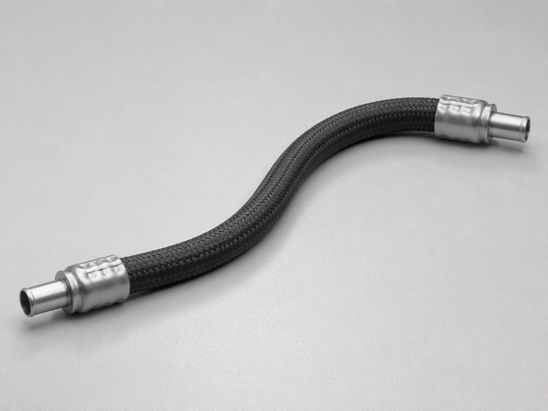
Figure 3. A HENGHUA 1/2-inch textile-braided air hose assembly. Bore, not brand, decides whether the motor sees full line pressure.
Because we manufacture the whole 1/4-to-1/2-inch bore range in one plant, we can supply the size your motor actually needs instead of the nearest stocked size. Custom lengths, port fittings, colors, and OEM/ODM branding are available at factory-direct pricing. Tell us your motor’s air consumption, run length, and system pressure, and contact our engineering team for a quote and samples.
Written by the HENGHUA Engineering Team — the engineers who build and pressure-test the hose assemblies we manufacture — with input from maintenance and production engineers running air motor installations. HENGHUA manufactures air hose assemblies from 1/4 inch to 1/2 inch, rated 200–500 PSI, with custom lengths, fittings, and OEM branding available.
 English
  Spanish
  Portuguese
  French
  German
  Arabic
  Russian
  Indonesian
  Japanese
  Korean