

Compressed air pressure loss is the gap between the pressure at your compressor outlet and the pressure that reaches the tool, and on a typical run it quietly eats 5–15% of the gauge reading. Most of that gap is friction: air dragging along the inside wall of the hose, the couplers, and every fitting in between. This guide separates friction loss from leakage loss, names the four variables that drive it, and walks through a hand calculation you can run with a tape measure. You also get a planning table for fittings, six ways to cut loss, and a method for sizing by loss budget.
Plan for 5–15% Pressure Loss on a Typical Hose Run
Plan on losing 5–15% of compressor gauge pressure across a normal workshop run, and treat anything past 10% as a signal to change the hose rather than crank up the regulator.
Loss grows steadily with air hose length and with flow, and it falls very fast as inside diameter grows. Against the baseline used across this site, a 3/8 inch hose loses roughly 2–5 PSI per 25 feet at common workshop flows. A 1/4 inch hose moving 8 standard cubic feet per minute loses about 6 PSI over 50 feet in measured tests. That is compressed air you already paid to compress.
Hold total pressure loss across a compressed air system under about 10% of inlet pressure, measured from the tank outlet to the tool inlet.
What Counts as Acceptable Loss?
At a typical 90–100 PSI setting, 10% leaves roughly 9–10 PSI of headroom to spend. Pneumatic tools are normally rated at about 90 PSI inlet, and they begin to lose torque, cycle speed, and finish quality below roughly 80 PSI. If your budget is tight, go one bore larger before you consider a bigger compressor.
A small pressure gauge fitted at the tool inlet is the fastest way to see where you stand, because the reading at the tank rarely matches the reading at the work.
Friction Loss vs Leakage Loss: Two Kinds of Compressed Air Pressure Loss
Friction loss in air hose is the continuous half of the total pressure loss. It happens because moving air rubs the hose wall, the coupler bore, and every fitting on the run. It never stops while air flows, and it climbs when you push more air through the same bore.
Leakage loss behaves differently. A worn O-ring, a cracked cover, or a loose thread bleeds air whether a tool runs or not, so it shows up even at zero demand. You find it with soapy water, a listening walk, or a simple pressure decay test. Our guide to air hose leak repair covers the detection sequence.
A quick test separates the two. Close the tool valve, watch the gauge for a minute, and note any fall while no air is flowing. Then open the valve and compare the two readings under load, because a gap that only appears under flow is friction.
The two fixes point in opposite directions. Upsizing hose will not stop a leak, and tightening a coupler will not reduce friction. Measure both, then act on whichever is larger.
The Four Variables: Length, Flow, Diameter, and Fittings
Every friction estimate is built from the same four inputs.
- Length — loss is linear with air hose length, so doubling the run doubles the loss.
- Flow — loss rises with the square of flow, so doubling the rate roughly quadruples it.
- Diameter — loss falls with about the fifth power of inside diameter.
- Fittings — every elbow, tee, and coupler adds resistance, usually counted as extra hose length.
Air hose diameter dominates the other three. Going from 1/4 inch to 3/8 inch bore more than doubles the cross-section, so velocity drops and friction collapses with it. That is why a short, fat hose beats a long, thin one at the same gauge pressure. Choose the largest bore your budget allows, because the extra cost is small next to the air you save.
If you are choosing a bore for the first time, the size chart by bore maps common tools to inside diameters. The companion explanation of how bore changes airflow covers the compressed air flow side of the same physics.
How to Estimate Compressed Air Pressure Loss in Air Hoses
You can estimate friction loss in air hose with two steps and a calculator. These relationships hold in any compressed air system.
The Friction Loss Formula in Plain English
Inside a normal hose, flow is turbulent, and friction loss follows a compact relationship. Loss is proportional to length, proportional to flow squared, and inversely proportional to inside diameter to roughly the fifth power. In compressed air flow, the diameter term dominates the result.
Loss (PSI) ≈ k × Length (ft) × Flow (SCFM)² ÷ Inside diameter (in.)⁵
Planning conditions: 100 PSI inlet, 68 °F (20 °C), clean dry air, straight run with no fittings. k is a material- and unit-dependent constant; use the worked example below to calibrate it against the site’s 2–5 PSI per 25 ft planning band.
Think of it this way. A narrow straw takes far more effort to draw through than a wide one, and pushing harder never changes the straw.
The full engineering form is the Darcy–Weisbach equation, where a friction factor, the air density, and the square of velocity all appear. For hand work, most engineers collapse it into one coefficient multiplied by length, flow squared, and the inverse fifth power of diameter. That simplification is close enough for planning when you stay inside the recommended flow range for the bore.
State your assumptions before you trust any estimate: inlet pressure, flow rate, air temperature, and whether the hose runs straight. Change the temperature and the air density shifts with it, moving the result by a few percent.
Worked Example: 50 Feet of 3/8 Inch Hose at 12 SCFM
Take a 3/8 inch hose 50 feet long feeding a tool at 12 SCFM, with 100 PSI at the outlet and air at 68 °F.
From the baseline, a 3/8 inch hose loses 2–5 PSI per 25 feet at typical flows, which is 4–10 PSI over 50 feet. The 8 PSI used here is a conservative upper-envelope design value for the whole assembly. It already allows for the couplers, the hose reel, and the elbows a real run carries, so it sits inside that 4–10 PSI band.
Now add fittings. A quick connect coupler pair at the compressor and a second pair at the tool count as 5–10 equivalent feet each. A conservative design takes the upper end of that range, about 10 feet per pair. A single 90 degree elbow adds about 3. Total equivalent length is 50 + 20 + 3 = 73 feet.
Loss scales linearly with length, so 8 PSI × (73 ÷ 50) ≈ 11.7 PSI. Round that to about 12 PSI, which is more than 10% of inlet pressure. The tool now sees roughly 88 PSI, just under its 90 PSI rating. A larger air hose diameter removes most of that loss. For a fill-in-the-numbers version, use the air pressure drop calculator method.
Friction Loss Looks Small per Foot, Until You Add the Run
A fraction of a PSI per foot sounds harmless. Multiply it by a real run, then by every fitting, and it becomes the most expensive air you own.
Table 1 turns the per-foot idea into planning numbers for compressed air pressure loss. Use it as a starting point, then confirm the result with a gauge at the tool.
Table 1. Estimated friction loss by hose inside diameter and flow (planning estimates at 100 PSI inlet, 68 °F / 20 °C, straight run, no fittings).
| Hose inside diameter | Typical flow at 90 PSI (SCFM) | Estimated loss per 25 ft (PSI) | Estimated loss at 50 ft (PSI) | Recommended maximum run |
|---|---|---|---|---|
| 1/4 in. | 5–10 | about 3 | about 6 | 25 ft |
| 3/8 in. | 10–20 | 2–5 | 4–10 | 50 ft |
| 1/2 in. | 20–35 | 1–2 | 2–4 | 100 ft |
Assumptions for Table 1: 100 PSI inlet at the compressor outlet, 68 °F (20 °C) air temperature, clean and dry air, a straight hose with no fittings, steady flow inside the recommended range, and a horizontal run. Values are rounded planning estimates, not laboratory figures.
Read the numbers as a shape, not a promise. A quiet shop that rarely runs a tool hard sits at the low end of each band, while a busy bay with two tools on one drop sits at the high end.
The pattern in the table is the lesson. Going from 1/4 inch to 3/8 inch roughly halves the loss at the same flow, and 1/2 inch halves it again as air hose diameter grows. A few PSI of loss near the compressor is easy to ignore. The same few PSI at the end of a long run is a hidden cost you pay on every cycle. The friction loss in air hose scales with the run, not with the regulator setting.
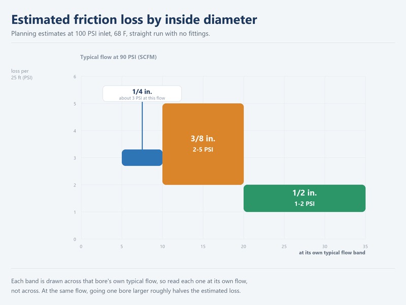
Figure 2. Estimated friction loss by air hose inside diameter and flow, built on planning assumptions rather than instrument-grade precision.
Equivalent Length of Fittings, Couplers, and Reels
Convert each fitting into extra straight hose, add it to the actual hose length, and estimate loss on the total.
Table 2 lists planning rules of thumb. Treat them as approximations that help you compare two layouts, not as specification values.
Table 2. Approximate equivalent length of fittings and devices (planning rule of thumb, not a specification; nominal 3/8 in. bore, 100 PSI inlet).
| Fitting or device | Approximate equivalent length | Where it usually sits |
|---|---|---|
| Quick-connect coupler pair | 5–10 equivalent feet | Compressor outlet and tool inlet |
| 90 degree elbow | about 3 ft | Hose ends and reel plumbing |
| 45 degree elbow | about 1.5 ft | Tight routing around equipment |
| Tee, flow through run | about 2 ft | Branch takeoff for a second bay |
| Tee, flow through branch | about 6 ft | Feed to a drop or a second tool |
| Full-port ball valve | about 1 ft | Isolation at the drop |
| Hose reel swivel | about 5 ft | Reel inlet and outlet |
Assumptions for Table 2: nominal 3/8 inch bore, 100 PSI inlet, 68 °F air, and steady turbulent flow. Real added resistance shifts with coupler style, actual bore, and flow rate, so verify with a gauge when the number is critical.
A single quick connect coupler pair is commonly counted as 5–10 equivalent feet of straight hose. On a 25 foot run, two pairs add 80% to the effective length before the air has moved an inch. A larger air hose diameter lowers that penalty across the whole run. As compressed air flow rises through the same fittings, the penalty grows faster still.
Reels make this worse in a way that is easy to miss, because the swivel and the spool inlet both add resistance that nobody counts on a drawing.
These values are a planning rule of thumb, not a specification.
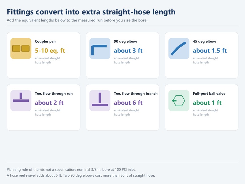
Figure 3. Elbows, couplers, and tees convert into extra straight-hose length, which is then added to the run.
Six Ways to Cut Pressure Loss in a Compressed Air System
Friction loss in air hose responds to design choices, not to more compressor pressure. Cut compressed air pressure loss at the least cost by working this list in order.
- Go one bore larger — moving 1/4 inch to 3/8 inch, or 3/8 inch to 1/2 inch, cuts loss more than any other single change.
- Shorten the run — loss is linear with air hose length, so move the drop or the reel closer to the work.
- Choose high-flow couplers — a full-bore quick connect coupler passes more air than a standard one at the same pressure.
- Minimize fittings — each elbow, tee, and swivel adds length that never appears on a drawing.
- Match flow to demand — pushing more compressed air flow than the tool needs multiplies loss through the squared flow term.
- Keep the hose straight — a kink is a partial blockage, so it hurts far more than its length suggests.
None of these changes requires a new compressor, and most of them take an afternoon. Diameter and length give the biggest wins for the least money, and fittings come next. If you are still narrowing a bore for one tool, start with the what size air hose do I need guide before you change anything else.
When Loss Is a Symptom: Kinks, Worn Couplers, and Undersized Hose
Not every pressure drop is a real design problem. Sometimes the hose is telling you that something physical has changed.
A kink under a reel or behind a machine chokes flow to a fraction of the rated bore. A worn quick connect coupler leaks and restricts at the same time. An undersized hose that was fine for a small tool becomes the bottleneck the day a bigger tool arrives. A collapsing liner can narrow the effective bore with no visible damage on the outside.
Before you redesign a whole system, walk the line, flex the hose at every bend, and check each coupler for play or hissing. Most sudden pressure loss is mechanical, not mathematical.
If the gauge at the tool recovers the moment you release the trigger, you are looking at a restriction. If it still sags while the tool is idle, the supply itself is short.
When Pressure Loss Signals a Failed Hose
Replace, never repair, any hose that shows a bulge, blister, cracked cover, exposed reinforcement, or a fitting that has been pulled loose. A hose that has already failed once will fail again, usually under pressure and often near a person. Retire the assembly, and pressurize only hose rated for the working pressure of your system. Lost air is annoying, but a new hose is far cheaper than an injury or a stopped line. OSHA 29 CFR 1926.302(b)(5) states that you must never exceed the manufacturer’s safe operating pressure. OSHA 29 CFR 1926.302(b)(7) requires a safety device at the supply end for hose above 1/2 inch.
Compressed Air Pressure Loss FAQs
Is friction loss the same as pressure drop?
No. The total pressure drop between two points has several causes, and friction is only one of them. The other common cause is leakage, plus any restriction such as a partly closed valve or a kink. When you measure, split the total into friction and leakage before you choose a fix, because the two repairs have nothing in common.
How much loss is acceptable in an air hose?
Keep total loss from tank to tool under about 10% of inlet pressure, which is roughly 9–10 PSI at a 90–100 PSI setting. Above that threshold, your compressed air pressure loss is too high, and tools rated at 90 PSI inlet begin to lose torque and cycle speed. If you cannot get under 10%, increase the bore before you raise the compressor setting.
Does a longer hose always lose more pressure?
Almost always. Loss is linear with air hose length, so a run twice as long loses twice as much at the same SCFM. Fittings break that simple rule, because two short hoses joined by extra couplers can lose more than a single longer hose. Count the equivalent length added by every fitting, not just the hose measurement on the label.
How much pressure do quick connect couplers add?
Each coupler pair adds 5–10 equivalent feet of straight hose. Standard bores also pass less air than the hose they join, so the coupler can become the real bottleneck near a tool. A full-bore, high-flow design reduces that penalty at a modest cost, especially on 1/2 inch and larger hose where the restriction matters most.
Does increasing compressor pressure fix friction loss?
No. Raising outlet pressure hides the symptom and raises energy use, while the loss itself stays roughly proportional to flow and length. It also pushes every component closer to its rated limit. Fix the cause with a larger bore, a shorter run, and fewer restrictive fittings, then set the regulator to the inlet pressure printed on the tool.
What temperature does the estimate assume?
The planning figures here assume about 68 °F (20 °C) air. Hotter air is less dense, so the loss shifts slightly, though the change stays small inside normal workshop temperatures. Very cold air raises density and can also stiffen a hose, which is a separate problem from friction and one worth handling on its own.
How do I measure loss in my own compressed air system?
Fit a gauge at the compressor outlet and a second gauge at the tool inlet, then run the tool under load. The difference between the two readings is your total pressure drop. Repeat with the tool off to separate leakage from friction; if the gap stays open with no flow, you are losing air to a leak.
My three bays share one compressor and the longest drop is 100 ft — where should I start cutting pressure loss?
Start with the longest run and the smallest bore on it. Count every coupler, elbow, and reel as added hose length, then step the bore up one size, because diameter drives loss far more than any other change. Use the site’s planning band of 2–5 PSI per 25 ft on 3/8 inch hose, keep total loss under about 10% of inlet pressure, and confirm the result with a gauge at the tool.
I am retrofitting an older workshop with steel pipe drops and rubber whip hoses — what loss can I expect at the tool?
Treat the steel drops and the whip hoses as one run with added length, then compare the total against the same planning band. Fit a gauge at the tool inlet before you buy anything, because the pipe, the couplers, and the whip hose each take a share, and a retrofit often hides one narrow fitting that carries most of the loss.
Specify Hose by Loss Budget, Not by Habit
Most workshops buy hose by habit, using the same part number for years regardless of the tool or the run. Two hoses of the same length and bore can behave very differently once their fittings are counted. A loss budget flips that habit. Decide the maximum PSI you can afford to lose, then choose the shortest, largest-bore hose that keeps you inside that number, and let the fittings and couplers follow.
HENGHUA manufactures reinforced air hoses and complete hose assemblies for workshops, distributors, and OEM brands, sized so that compressed air pressure loss stays inside your budget. Every air hose we build uses a high-tensile textile reinforcement layer with an abrasion- and oil-resistant cover, is rated 200–500 PSI, and leaves the factory with crimped brass fittings and a pressure test on every batch.
We supply 1/4, 3/8, and 1/2 inch bore in rubber, PVC, polyurethane, and hybrid constructions, with custom lengths, fittings, colours, reels, and OEM/ODM branding. Because we control compounding, extrusion, braiding, and crimping in one plant, lead times stay short for bulk orders and the specification on the label is the specification you get. If you are sourcing air hoses for retail, distribution, or industrial use, send us your specification and we will quote against it. Get a quote and free samples
Final Verdict: Short, Straight, and One Size Up
Compressed air pressure loss is a solvable design problem, and friction is usually the largest share of it. Estimate the loss on your actual run, convert every fitting into added length, and keep the total under about 10% of inlet pressure. When you are unsure, choose a shorter hose and one size larger bore, because that single decision removes more lost air than any coupler upgrade or regulator tweak. Then verify the result with a gauge at the tool, and source hose that matches the number you calculated rather than the habit on the shelf.
Written by the HENGHUA engineering team, with input from workshop and maintenance teams across North America and Europe. HENGHUA manufactures reinforced air hoses and hose assemblies in rubber, PVC, polyurethane, and hybrid constructions, from 1/4 inch to 1/2 inch, rated 200–500 PSI, with custom lengths, fittings, colours, and OEM branding.
 English
  Spanish
  Portuguese
  French
  German
  Arabic
  Russian
  Indonesian
  Japanese
  Korean