
Hydraulic hoses fail for eight recurring reasons — abrasion, mis-selection, installation twist, bend radius violations, pressure spikes, thermal degradation, fluid contamination, and fitting or crimp failure. Every one of these hydraulic hose failure causes is preventable with the right specification and a fixed inspection routine. Most failures are maintenance problems rather than manufacturing defects: the warning signs are usually visible long before a hydraulic hose burst occurs, and the practices below are what extend hydraulic hose service life in real equipment.
Three numbers decide whether you prevent these failures. Inspect a safety-critical machine every shift, and in detail every 250–500 operating hours. Leave two hose diameters of straight run behind the coupling before any bend starts, and rate the hose against the temperature measured at the hose rather than at the reservoir. Where abrasion and installation errors are counted together they explain roughly two-thirds of premature failures, and abrasion alone is the largest single cause.
If you maintain excavators, loaders, presses, or any machine with a hydraulic circuit, the question worth answering is why do hydraulic hoses fail on your specific equipment, and which of these eight causes your operating conditions expose. The sections below take each cause in turn with the prevention step for each. They then give a diagnostic table you can use on a failed hose, and a hydraulic hose failure prevention program you can put into service this week.
Which 8 Causes Account for Most Hydraulic Hose Failures?
Eight causes account for most hydraulic hose failures, and each one damages a different part of the hose. The table below lists all eight with the layer each one attacks and the single prevention step that removes it. Abrasion and external damage takes the cover, mis-selection takes the whole assembly from the first pressure cycle, installation twist misaligns the reinforcement, and a bend radius violation concentrates stress at the bend. Read the rows that match the conditions on your machines, then go to the sections for the mechanism and the warning signs.
The 8 most common hose failure causes, the layer of the hose each one damages, and the first prevention step for each.
| # | Cause | What it damages | Primary prevention step |
|---|---|---|---|
| 1 | Abrasion and external mechanical damage | Outer cover, then reinforcement | Abrasion sleeves, clamps, rerouting away from contact points |
| 2 | Mis-selection (pressure, temperature, fluid) | Entire assembly, from the first cycle | Specify from system relief pressure, max temperature, and fluid compatibility |
| 3 | Installation errors (twist, tension, length) | Reinforcement alignment, crimp joint | Verify the layline runs straight; allow correct slack |
| 4 | Bend radius and routing violations | Reinforcement at the bend | Maintain published minimum bend radius at every point |
| 5 | Pressure spikes and over-pressure | Reinforcement, tube, crimp | Check relief settings; add accumulators or surge suppression |
| 6 | Thermal degradation (heat and cold) | Inner tube and cover elastomers | Match temperature rating to worst-case fluid and ambient temperature |
| 7 | Fluid contamination and chemical incompatibility | Inner tube, from the inside out | Maintain an ISO 4406 cleanliness target of 18/16/13 or better; verify fluid compatibility |
| 8 | Fitting, crimp and assembly failure | Coupling joint, ferrule, threads | Use matched hose-and-fitting systems with verified crimp diameter |
How Does a Hydraulic Hose Fail? The Three Layers and What Each One Tells You
Scope of this guide. This guide covers why flexible hydraulic hose assemblies fail, and what prevents each failure, in mobile and industrial hydraulic circuits using SAE 100R braided and spiral-wound constructions. It applies to machines such as excavators, loaders, presses, and similar equipment where hoses are routed, flexed, and pressure-cycled in service.
Two neighbouring subjects have their own treatment: faults inside the hydraulic system that are not hose-related, which belong with a system maintenance and troubleshooting review, and hose selection for non-hydraulic service. Where failures keep returning to the same circuit, treat it as a system fault rather than a hose problem and review that system before the hose.
A hydraulic hose fails through one of three layers, and knowing which layer is degrading tells you which cause is at work. Every hydraulic hose assembly is a composite of three elements. An oil-resistant inner tube carries the fluid. One or more layers of steel wire reinforcement hold the rated hydraulic hose working pressure. An outer cover protects the reinforcement from the environment.
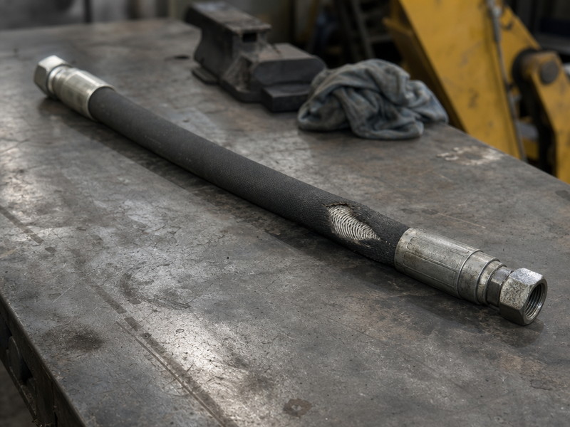
Figure 1. A typical field failure: the cover has worn through at a contact point, exposing the reinforcement that contains system pressure.
A hydraulic hose fails in sequence, layer by layer, rather than all at once. External causes attack the cover first; once the cover is breached, moisture and contaminants reach the wire, which corrodes and loses tensile strength. Internal causes attack the tube first, softening, swelling, or eroding it until the fluid finds a path to the reinforcement. Pressure-related causes load the reinforcement directly, and fatigue accumulates cycle by cycle until wires fracture (see Figure 2).
The Three Failure Paths and What They Look Like
Failure path by layer, the causes that drive it, and the visible evidence it leaves behind.
| Failure path | Dominant causes | Visible evidence |
|---|---|---|
| Cover-first (outside in) | Abrasion, external damage, UV and ozone | Worn or missing cover, exposed or rusted wire, flat spots |
| Tube-first (inside out) | Contamination, chemical incompatibility, high fluid velocity | Swollen or blistered cover, flaking tube material at the fitting, discolored fluid |
| Reinforcement-first (load driven) | Over-pressure, pressure spikes, bend radius violations, impulse fatigue | Wire fracture under intact cover, straight or spiral burst tear, hose that retains a bend |
A hose that bursts with the cover still intact has almost certainly failed from a load or fatigue path rather than from abrasion (see Figure 3), and that distinction changes the corrective action. Where cover damage is present, the fix is protective and routing-based. Where the cover is clean, the fix is in the system: relief valve settings, pressure spike suppression, bend radius, or impulse rating.
1. Abrasion: Why Does Rubbing Wear Through a Hydraulic Hose?
Hydraulic hose abrasion is the most frequently reported failure cause in field applications. Repeated contact between the cover and a machine surface, a sharp edge, or another hose mechanically removes cover material until the reinforcement is exposed.
Abrasion does not require a sharp edge to be destructive. Vibration against a smooth steel surface removes cover material progressively, and the damage concentrates where the hose is clamped or where it passes a structure. Once the wire is exposed, corrosion accelerates in wet or dusty environments and the reinforcement loses the tensile capacity it needs to contain pressure.
Warning signs of hydraulic hose abrasion damage:
- Flattened, polished, or scuffed areas along the cover
- Fabric or wire texture visible beneath a thinned cover surface
- Rust staining at a contact point
- Localized bulging next to a worn section
How to prevent hydraulic hose abrasion:
- Fit abrasion sleeves or spring guards at every known contact point
- Clamp the hose so it cannot move against the structure
- Reroute any run where cover-to-metal contact cannot be eliminated
- Bundle only hoses that flex in the same direction — hoses that flex in opposite directions rub against each other and remove cover material at the bundle
A documented boom-circuit case is worth reading in full before you decide this cause is not present on your machines. A 35-ton excavator in quarry duty lost the same boom hose twice inside roughly 90 operating days. The recorded fix — abrasion sleeve at the contact point, rerouting clear of the steel frame, and correcting a slight twist — extended hydraulic hose service life on that circuit past 14 months.
The full inspection record and the second, heat-related case sit in our documented field failure cases. What makes both cases useful is the sequence rather than the machine: the wear mark and the layline were both visible long before the failure.
My 20-ton excavator blew the same boom hose twice in three months — what should I check before I fit a third one?
Read the failed hose before ordering anything. A cover worn through at a contact point points to routing and abrasion protection; a layline that spirals points to a twisted installation; a straight tear under an intact cover points to a pressure or impulse problem. Two failures on one circuit in three months is the classic signature of an installation or system cause that survived the first replacement.
Our quarry machines rub hoses against the boom frame — which abrasion protection actually lasts a full season?
A split-style sleeve fitted at the actual contact point is the practical answer for a steel-on-cover contact that cannot be routed out, and it is what the recorded case above used. Protection only works where the contact is: a sleeve fitted along the run but not at the rubbing point changes nothing. Where cover-to-metal contact can be removed by rerouting or by adding a clamp, do that instead of adding a sleeve over a moving hose.
2. Mis-Selection: Which Pressure, Temperature or Fluid Rating Did You Get Wrong?
Mis-selection is a leading cause of premature hose failure because it puts the hose outside its design envelope from the first pressure cycle, so no amount of correct installation or maintenance can compensate.
Selection errors take four common forms. Two are pressure-related: a hose rated below the system’s relief pressure, and a standard-duty construction used where the circuit produces continuous high-pressure cycling. Two are condition-related: a temperature rating below the actual fluid or ambient temperature at the hottest point, and a tube compound incompatible with the hydraulic fluid or with an external chemical. Each error shortens service life in a different way — pressure overload fractures wire, temperature overload hardens the tube, incompatibility swells it, and cycling fatigue cracks the reinforcement.
How to prevent hose mis-selection: set the specification from the machine rather than from the hose you are replacing. Read four values from the machine: the relief valve setting, the maximum system oil temperature at the hottest operating condition, the fluid type, and the circuit’s cycling behaviour. Match the hose’s printed working pressure, temperature range, and tube compound to those four values.
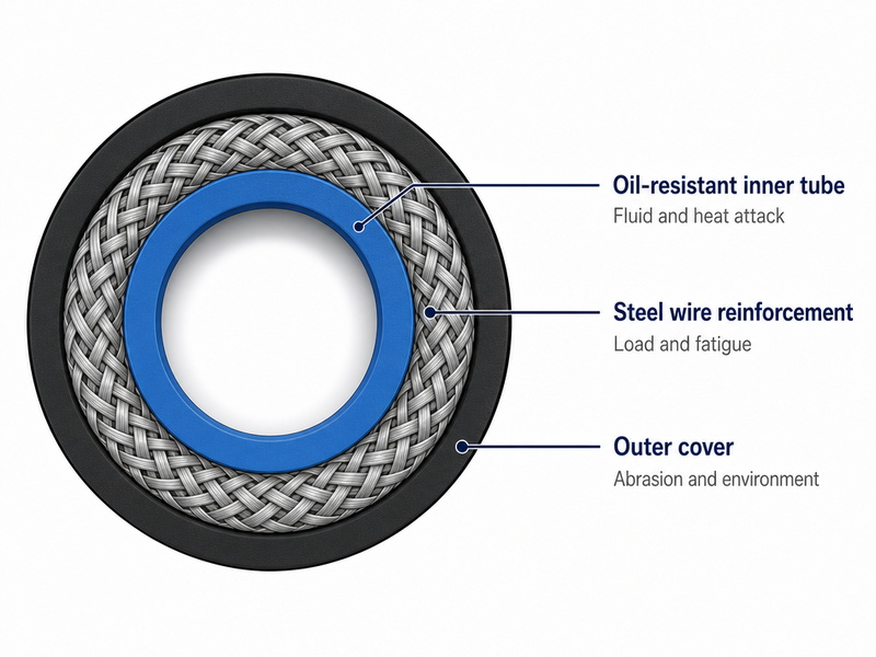
Figure 2. Each hose layer fails from a different cause: the tube from fluid and heat, the reinforcement from load and fatigue, the cover from abrasion and the environment.
A practical check on the margin you are buying: SAE J517 requires a minimum burst pressure of four times the maximum working pressure across its 100R series. A hose rated at 4,000 PSI working pressure is therefore destructively tested at a minimum of 16,000 PSI. A third figure, proof pressure, sits at roughly 1.5 times working pressure and is the pressure at which the assembly is tested without being destroyed.
The four-to-one ratio is a safety factor rather than a licence to run a lower-rated hose at a higher system pressure. If your relief valve is set at 5,000 PSI, a 3,000 PSI hose is mis-selected regardless of how well it is installed. The working rating and the minimum burst figure are measured by different tests, and the gap between them is what keeps a correctly selected assembly inside its design envelope.
My relief valve is set at 3,000 PSI but the gauge reads 2,200 when running — what working pressure should I order?
Specify from the relief valve setting, not from the gauge. 3,000 PSI is the highest pressure the circuit can produce, so the hose’s published working pressure has to exceed 3,000 PSI with margin. If the measured spikes run higher than the relief setting, they set the figure instead. Ordering against a 2,200 PSI running reading leaves the assembly rated below the pressure the circuit can actually reach.
How Much Margin Should a Hose Have Above Circuit Pressure?
Keep at least 10% between the highest circuit pressure and the hose rating. A hose run permanently near its rated working pressure ages faster because the reinforcement carries continuous load. Where the highest pressure the circuit can produce comes within 10% of the hose’s published working pressure, specify one construction class higher rather than accept that margin. The highest pressure is the relief valve setting, or a measured spike if one runs higher. Then check whether pressure spikes (Cause 5) push the circuit above its rating during normal operation.
3. Installation Errors: Why Does Twist, Tension or Length Cause Failure?
Hydraulic hose twist is the most destructive installation error, because it misaligns the reinforcement wires without leaving external damage — the hose looks serviceable while its pressure capacity is already reduced.
Hydraulic hose reinforcement is wound as a helix. When the assembly is twisted during installation, the wires are forced into a different helix angle than designed, and the load path between the wire layers changes.
Uneven stress distribution follows, and the hose then fails at flex or impulse far earlier than its rating suggests. The 90% rule our own field guide publishes puts a number on that: at about 7 degrees of twist, expected life falls by up to 90%, and at about 5 degrees by up to 70%. Tension produces similar damage by a different route — a hose installed too short is permanently loaded at the crimp joint, which is where the leak first appears.
How to prevent hydraulic hose twist: read the layline. The continuous printed text along the cover must run straight along the hose when the assembly is installed. If the layline spirals, the hose is twisted and must be reinstalled rather than clamped into position. What each marking on the layline means, and how to use it to confirm you have the right assembly, is covered in how to read a hose layline.
How to prevent tension: measure the routing at the most demanding machine position, not in the parked position. A hose assembly can shorten by as much as 4% when it is pressurized, and it also contracts as the fluid cools, so a run measured tight will pull on the crimp joint in service. Allow for that movement and leave 2–4% slack for contraction and expansion rather than installing the run tight.
Why Does a Hose Fail Weeks After Installation?
Failures that appear within the first weeks usually trace to installation rather than material. A twisted hose, an assembly fitted under tension, a crimp damaged by over-torquing at the port, or a bend radius already violated at the fitting will all fail early. When a hose fails within its first month in service, re-check the installation before ordering a replacement — a new hose installed the same way will fail the same way.
4. Bend Radius: How Tight Is Too Tight for a Hydraulic Hose?
Bending a hose tighter than its published minimum bend radius concentrates stress on one side of the reinforcement, and repeated flexing at that point produces fatigue failure that no pressure rating can prevent.
Every hydraulic hose has a published minimum bend radius, and SAE J517 sets one per construction and size; for steel wire braid hose it typically falls between five and eight times the hose outside diameter. Read the published figure for your size rather than estimating, because the value changes with construction class.
Wires on the outside of a tight bend stretch while the wires on the inside compress, and the tube wall thins on the outer side. Flexing then works the same wires at the same location, which is the mechanism behind a paperclip breaking when bent back and forth. A related error is bending in two planes close together, which combines bending stress with torsion — that is, twist about the hose axis — in a single length of hose.
Warning signs of a bend radius violation:
- A kinked or flattened appearance at the bend
- Cover cracking concentrated at a single point
- A hose that retains a curved set after removal from the machine
How to prevent bend radius violations:
- Maintain the published minimum bend radius at every point of the run, including the short length immediately behind the fitting, where violations are most common
- Keep the hose straight for at least two hose diameters behind the coupling before it starts to bend
- Where space is restricted, change direction with an angled adapter or a bent-tube coupling rather than bending the hose tighter
- Break multi-plane runs into separate bends with a straight section between them
Where a smaller bend is unavoidable, work from the published figure for that construction rather than from the tightest bend that happens to fit. The practical effect of tighter bends on flow and service life is covered in minimum bend radius in practice.
We replaced every hose on a concrete pump last year and they are now cracking just behind the fittings — what went wrong?
Cracking concentrated immediately behind the coupling is the signature of a bend that starts too close to the fitting, not of a bad batch of hose. The straight length behind the coupling is the most frequently violated part of the run, and a whole set of hoses replaced at once will all share the same routing fault. Re-check the clearance at each fitting on the worst circuit before the replacement set goes on.
5. Pressure Spikes: Why Does a Hose Burst With the Cover Intact?
Pressure spikes damage hoses more often than steady over-pressure, because a transient can exceed the hose rating for milliseconds while the system gauge never shows it. A hydraulic hose burst that leaves the cover unmarked is usually the work of a spike, and the evidence points to load rather than to a surface defect.
Spikes come from valve closure, rapid cylinder reversal, load-induced pressure intensification, and thermal expansion in closed circuits. Each spike loads the reinforcement and the crimp joint briefly but repeatedly, and the cumulative effect is impulse fatigue — measured as the number of pressure cycles a hydraulic hose survives before failure. That is why impulse cycling, not static pressure, is the standard durability test. It is also why the impulse rating of an assembly is the better predictor of hydraulic hose service life in a high-cycle circuit than its static burst figure.
Under ISO 18752:2017, the impulse requirement is set by hose type, with Type A carrying a minimum of 200,000 cycles. Above that floor, the ladder runs to 400,000 cycles for enhanced durability and 1,000,000 cycles or more for premium durability, all measured under impulse testing at 133% of the rated working pressure. The test methods behind those figures are set out in the hydraulic hose impulse and hydrostatic testing standards. High-cycle applications such as excavator boom and arm circuits benefit from assemblies rated above the 200,000-cycle floor.
How to prevent pressure spike damage:
- Verify that the relief valve opens at its set pressure and is not stuck before you replace another hose on the same circuit — a faulty relief valve is a common root cause of repeat bursts
- Where the circuit produces sharp transients, fit an accumulator or surge-suppression device to absorb the peak before it reaches the hose
- Confirm that the rated hydraulic hose working pressure still exceeds the highest spike the circuit can produce, not just the nominal system pressure
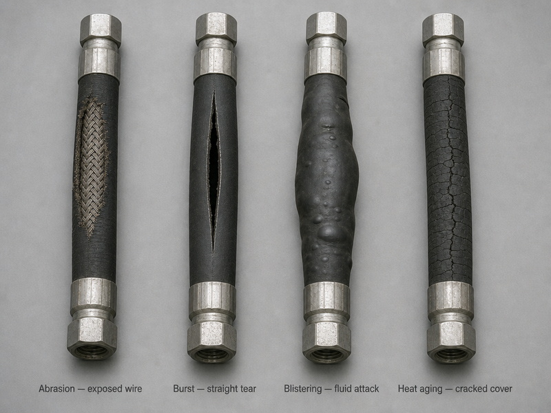
Figure 3. Failure patterns identify the cause: abrasion leaves worn cover, over-pressure leaves a straight tear, chemical attack blisters the cover, and heat aging cracks it.
6. Thermal Degradation: How Hot or Cold Is Too Much for a Hose?
Heat is the most common environmental killer of hose elastomers, and its damage is internal — the hose hardens, loses flexibility, and fails from a crack rather than a burst.
Standard 100R-series compounds are commonly rated to 100°C fluid temperature, with high-temperature constructions available at 125°C and above. The rating that matters is the one printed for the construction you are buying, measured against the highest temperature the hose actually experiences. The practical rule is that the hose temperature rating must exceed both the maximum hydraulic oil temperature and the ambient temperature at the hose’s location.
External heat sources matter as much as fluid temperature: a hose routed close to an exhaust manifold can be damaged even when the system oil is within limits, because radiant heat attacks the cover and outer reinforcement locally. At the cold end, standard elastomers become stiff below about −40 °C. At around −20 °C the bend radius requirement is effectively double the room-temperature figure, so a route that passes in summer can be a violation in winter.
Warning signs of thermal degradation:
- A hard, brittle, or glossy cover
- Fine surface cracks that deepen over time
- Discoloration or blistering near a heat source
- Hardened or cracked tube material visible when the fitting is removed
How to prevent thermal degradation:
- Measure the temperature at the hose, not only at the reservoir
- Where a hose must run near a heat source, install a heat shield or maintain clearance from the hot surface
- Where the measured temperature approaches the temperature rating, specify a higher-temperature construction rather than monitoring the difference
- In cold conditions, allow the machine to warm before full-pressure operation
I need a hose that sits near the exhaust manifold on a telehandler and sees 120 °C oil — what temperature rating do I specify?
Specify a high-temperature construction rather than a standard 100°C compound, because the hose has to survive both the 120°C fluid and the radiant heat from the manifold. A 125°C-rated construction is the starting point, and the hose still needs a heat shield or added clearance at the manifold, since radiant heat attacks the cover locally at temperatures the fluid reading does not show. Measure at the hose surface as well as in the oil to confirm what the cover actually sees.
Our log splitter hose fails every winter at about −25 °C — is it the cold or the hose we bought?
Cold weather and the hose construction both drive winter failures, and the cold is the part you can act on. At around −25 °C the bend radius requirement is already more than double its room-temperature figure. Re-check the route for a bend that only becomes a violation once the hose is stiff. Let the machine warm before full-pressure operation, and specify a construction rated for the lowest ambient temperature the machine sees.
7. Contamination: Why Does a Hose Fail From the Inside Out?
Contamination and chemical incompatibility attack the inner tube, so the hose degrades from the inside and can fail while the cover still looks new.
Contamination takes three forms:
- Hard particles — metal fines and sand erode the tube surface, creating roughness and potential leak paths
- Water ingress — moisture accelerates oxidation and promotes sludge formation inside the circuit
- Chemical attack — incompatible fluids and aggressive external chemicals swell, blister, soften, or extract the plasticizers that keep the rubber flexible
High fluid velocity compounds particle damage by washing the tube surface. Practical limits are around 25 ft/s (7.6 m/s) on suction lines and 35 ft/s (10.7 m/s) on pressure lines; a suction or return line handling oversized flow deserves particular attention. When an assembly is flushed or refitted, follow a written hydraulic hose cleaning procedure to ISO 4406 rather than a workshop rinse.
Warning signs of tube damage:
- A swollen or blistered cover
- Fluid weeping from a crimp with no visible external damage
- Flaking or eroded tube material at the fitting
- Discolored or contaminated oil in the reservoir
How to prevent tube damage from contamination:
- Hold fluid cleanliness to a defined target — 18/16/13 or better on the ISO 4406 scale — sample the oil on a schedule, and replace filters before they load
- Confirm the tube compound is compatible with the actual hydraulic fluid and with any chemical the hose contacts externally
- Store spare hoses in a cool, dry place away from ozone sources such as electric motors and welding equipment
A hose off our press looks untouched on the outside but the cover is swollen — what does that tell me about the fluid?
A swollen or blistered cover with no external damage points to the tube, which means the fluid has reached the reinforcement from the inside. The usual causes are a tube compound incompatible with the hydraulic fluid or with a chemical the hose contacts externally, and occasionally sustained high fluid velocity eroding the tube surface. Check the fluid specification against the tube compound you are buying before the replacement assembly goes on.
8. Fittings and Crimps: Why Does a Hose Leak at the Coupling?
Fitting and crimp failures are hydraulic hose assembly quality failures, and they most often appear as leakage or blow-off at the coupling rather than as a burst in the hose body.
An under-crimped ferrule cannot grip the hose sufficiently and the assembly blows off under pressure; an over-crimped ferrule cuts into the reinforcement and creates a stress riser that fails later. Insertion depth matters as much as crimp size. A hose pushed only part of the way into the fitting shell leaves too little cover under the ferrule. That is one of the most frequently recorded assembly faults, and it is why suppliers publish a marking or an insertion-depth gauge for each fitting series.
Mixing a fitting from one manufacturer with hose from another — unless the two manufacturers have verified compatibility — removes the dimensional relationship the crimp specification depends on.
Over-torquing the fitting into the port deforms sealing surfaces, corrosion on the fitting breaks the seal, and damaged threads prevent correct assembly. Fitting failures also drive much unnecessary hydraulic hose replacement, because a leaking coupling looks like a failed hose and the true assembly defect is never recorded.
How to prevent fitting and crimp failure:
- Use hose and couplings approved together as a matched hydraulic hose assembly system
- Push the hose to the published insertion depth, or to the marking the supplier provides, before crimping
- Lubricate the assembly path as the fitting supplier specifies, so the tube is not cut or pinched as the shell is pushed on
- Crimp with equipment calibrated for that specific fitting series, and verify the crimp diameter with a go/no-go gauge rather than by eye
- Use the double-wrench method when tightening the fitting to the port, so torque is not transferred into the crimp
- Protect fittings from corrosion and impact damage, and fit new couplings on every new assembly — a coupling removed from a failed assembly carries the stress history of that failure and is replaced with the hose
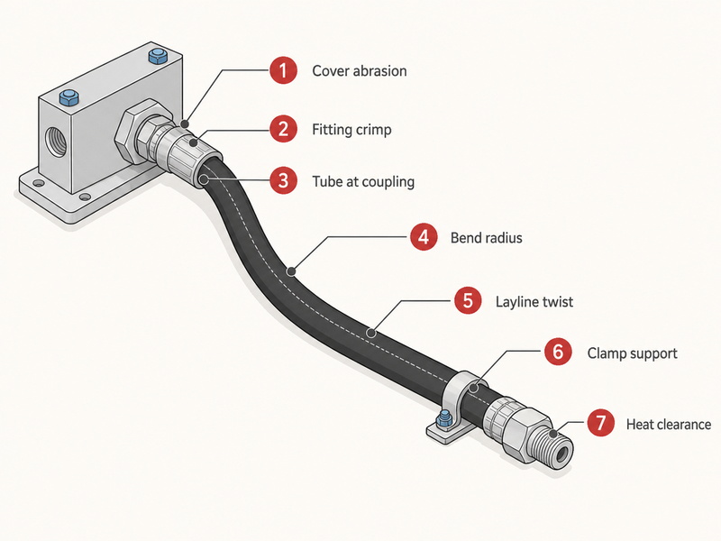
Figure 4. Seven inspection points cover the eight failure causes: cover, crimp, tube at the coupling, bend radius, layline, clamps, and heat clearance.
I crimped my own assemblies on a borrowed machine — how do I confirm the crimp diameter before putting them into service?
Confirm three things before the first assembly goes into service. The crimping machine must be calibrated for that ferrule series. The hose and fitting must come from a matched system. The finished crimp must measure inside the supplier’s published range for that combination. A caliper reading alone will not tell you whether the specification matches the hose you used, so work from the supplier’s gauge and the supplier’s table rather than from a measurement on its own.
Why Do Hydraulic Hoses Fail on Your Machines? Root Cause Diagnosis
Identify the root cause by reading the failure pattern before replacing the hose, because each cause leaves different physical evidence — and an unexplained repeat failure usually means the underlying cause was never corrected. This table works from the failed hose backwards to the cause, and it is deliberately narrower than a general symptom checklist. Each row is anchored to one of the eight hydraulic hose failure causes above, so the pattern you find tells you which section to act on. It is also the fastest way to answer why do hydraulic hoses fail on one circuit while an identical machine on the same duty runs without failures.
Failure pattern diagnostic: use the visible evidence on the failed hose to identify the root cause and the corrective action.
| Failure pattern | Most likely cause | Corrective action |
|---|---|---|
| Cover worn through, wire exposed or rusted | Abrasion (Cause 1) | Add abrasion sleeve, clamp and reroute the run |
| Cover polished or flattened but not worn through | Early abrasion at a clamp or a structure (Cause 1) | Re-clamp, add a sleeve, and recheck at the next detailed inspection |
| Straight tear in the hose body | Over-pressure or pressure spike (Cause 5) | Check relief valve setting and function; add surge protection |
| Spiral tear along the reinforcement | Reinforcement fatigue under impulse cycling, or hydraulic hose twist (Cause 3 or 5) | Verify layline; specify a higher impulse-rated assembly |
| Layline spirals along the cover | Hydraulic hose twist (Cause 3) | Reinstall the assembly with the layline running straight |
| Cover swollen or blistered with no external damage | Fluid or chemical incompatibility (Cause 7) | Match the tube compound to the fluid and to any external chemical the hose contacts |
| Cracking at a single point away from the coupling | Bend radius violation or radiant heat (Cause 4 or 6) | Increase bend radius; shield from the heat source |
| Cracking concentrated immediately behind the coupling | Bend radius violation behind the fitting (Cause 4) | Re-route with clearance behind the coupling |
| Hard and brittle hose with fine cracks | Thermal or environmental aging (Cause 6 and exposure) | Replace; uprate temperature class; reduce exposure |
| Leakage at the fitting, hose body intact | Crimp or assembly defect, over-torque (Cause 8) | Replace assembly; verify crimp diameter and fitting system |
| Tube flaking or erosion at the coupling | Particle contamination or high velocity (Cause 7) | Improve filtration; review circuit flow velocity |
| Hose retains a bend after removal | Bend radius violation or mis-selection (Cause 2 or 4) | Reroute; check the specified construction against the circuit |
Reading the failure pattern before replacing a hose is what stops the same failure repeating. A hose that fails again after replacement is evidence that the cause was never addressed, and each repeat failure carries the cost of the assembly, the labour, the lost fluid, and the downtime. Recording the failure pattern alongside the operating hours at failure builds the dataset you need to schedule hydraulic hose replacement on comparable machines instead of reacting to bursts.
How Do You Prevent Hydraulic Hose Failure in Practice?
Hydraulic hose failure prevention comes down to three things: correct specification at purchase, correct installation at replacement, and a scheduled inspection routine that finds damage before it becomes a burst.
Which of These Five Situations Matches Yours?
- If you run a single machine on a farm or small site: inspect it every shift, and set the detailed check at 250–500 operating hours. Protect every contact point with an abrasion sleeve before the cover wears through.
- If you maintain a quarry or mining fleet: treat boom and arm circuits as high-cycle, and specify an assembly above the 200,000-cycle impulse baseline. Record the operating hours at each failure so replacements can be scheduled rather than reactive.
- If you are a mechanic replacing a failed hose today: read the failure pattern first, and confirm you are not repeating the same installation. Verify the crimp diameter on the new assembly with a go/no-go gauge before it goes on.
- If you are a maintenance planner building a schedule: set inspection intervals from machine duty, and keep a per-machine record of installation date and failure pattern. Use the age limits as backstops — roughly two and a half years exposed, five years protected, ten years maximum.
- If you are a distributor specifying replacements across a fleet: keep the part number and crimp diameter consistent so assemblies stay interchangeable, and specify from the machine rather than from the hose being replaced.
Prevention at Specification
Hydraulic hose failure prevention starts at specification, not at the replacement. Confirm the hydraulic hose working pressure, temperature range, fluid compatibility, and impulse rating against the circuit rather than against the hose being replaced. For high-cycle circuits, select an assembly with an impulse rating above the baseline requirement, and keep the replacement part number consistent across a fleet so maintenance teams are not improvising under pressure.
Prevention at Installation
Verify the layline is straight, maintain the minimum bend radius including behind the fitting, and allow slack for expansion and contraction. Clamp supported runs at 24–36 inches (600–900 mm) intervals, and protect every contact point (see Figure 4). On the field-returned assemblies our HENGHUA engineers have examined, the two findings that repeat most often are cover abrasion at a contact point and twist or bend stress at the fitting. Those are the two causes our own field records rank first and second, and both are visible before failure if someone looks.
Prevention Through Inspection
A hydraulic hose inspection routine run to a fixed interval finds damage while it is still visible and correctable, which is what separates planned hydraulic hose replacement from unplanned downtime. Repeated failures on one circuit belong to the system rather than to the hose, and the hydraulic system maintenance and troubleshooting checklist covers that side of the diagnosis. Set the hydraulic hose inspection interval from the duty of the machine rather than from a single site-wide rule. Use a written hydraulic hose inspection checklist so a different person gets the same answer on the same hose.
Recommended hydraulic hose inspection frequency by equipment duty, with the damage each interval is intended to catch.
| Inspection level | Frequency | What to check |
|---|---|---|
| Operator visual check | Before each shift on safety-critical machines | Leaks, cuts, exposed reinforcement, obvious rubbing |
| Detailed inspection | Every 250–500 operating hours | Cover wear at contact points, layline straightness, clamp condition, bend radius, heat exposure, fitting corrosion |
| Replacement review | At recommended age limits regardless of appearance | Service-life limits by application severity |
I am writing a preventive maintenance schedule for 12 machines — how many operating hours between hose inspections should I set?
Set one interval per machine class rather than one number for the fleet. For safety-critical machines the operator check stays on the pre-start sheet before every shift, and the detailed recorded inspection runs at 250–500 operating hours on standard duty. Use the shorter end for high-cycle, high-temperature, or abrasive duty, and the longer end only where hoses are protected and lightly cycled.
Age limits apply on top of condition, not instead of it. Industry practice replaces hoses in high-risk exposed positions at roughly two and a half years and standard protected hoses at about five years, with a ten-year maximum regardless of appearance. Machines in high-cycle, high-temperature, or abrasive conditions reach those limits sooner.
Replace a hose when any of these conditions is present:
- Reinforcement exposed by cover wear
- A cover cut deep enough to reach the reinforcement layer
- A bulge or blister anywhere along the assembly
- A cover that has hardened or cracked
- Fluid weeping at a crimp
Each condition ends the assembly’s service life on its own. A hose that still holds pressure behind a bulged or cut cover is already below its rated strength, and replacing it early costs a fraction of the downtime a burst would cause. Keep a simple record per machine — installation date, inspection notes, and reason for replacement — so you can see whether failures are declining and identify the circuits that need design attention rather than more replacements.
Foire aux questions
Why do hydraulic hoses fail at the fitting rather than in the hose body?
Fitting-area failures belong to the assembly and the installation. Four causes account for most of them: an under- or over-crimped ferrule, a fitting series that does not match the hose, over-torque at the port that deforms the seal, and a bend radius violation immediately behind the coupling. The bend radius fault is the one that keeps loading the joint as the machine moves.
How do I tell an installation fault from a hose defect when a replacement fails again?
An installation fault is the more likely explanation, and the failure pattern tells you which. Look for the layline spiral of a twisted fit, or a bend that starts within two hose diameters of the coupling. Then check for a run installed under tension, and for a contact point that abrades the new hose exactly as it did the old one. A genuine hose defect is a much rarer finding, and it shows up across several circuits rather than repeatedly on one.
Which failures are most common on excavators and loaders specifically?
On excavators and loaders the pattern follows the machine: maximum articulation, exposed routing, and a tight bend immediately behind the coupling. Abrasion where a hose rubs the boom or the frame comes first, twist introduced at reinstallation comes second, and bend radius violations at articulation points come third. Mis-selection and thermal degradation take over in high-pressure, high-temperature circuits.
What is the most common cause of hydraulic hose failure?
In our own field records the ranking of hydraulic hose failure causes is stable: abrasion first at roughly 35–40% of cases, with installation and routing errors next at about 25–30%. Counted together, external damage and installation problems account for the majority of premature failures — which means most failures are maintenance and specification problems rather than manufacturing defects.
What does a twisted hydraulic hose look like?
Twist is identified by the layline — the printed text running along the cover. On a correctly installed hose the layline runs straight along the length; on a twisted hose it spirals around the cover. A visible spiral means the reinforcement is misaligned, and the magnitude is specific rather than general: a twist of about 5 degrees can cut expected life by up to 70%, and about 7 degrees by up to 90%.
Can I repair a hydraulic hose instead of replacing it?
Replacement is required whenever the cover, reinforcement, or tube is damaged. A field repair that reuses the existing crimp leaves the assembly below its pressure rating. So does clamping a fitting onto a damaged hose. Fit a new assembly built from matched components and a verified crimp diameter.
How hot can a hydraulic hose run before the compound breaks down?
Above roughly 100 °C at the hose surface, a standard 100R-series compound is working outside its comfort zone, and the answer is a 125 °C construction rather than more monitoring. Radiant heat from an exhaust or manifold counts toward that figure, so a run passing close to a hot surface can exceed its rating even when the oil temperature looks acceptable on the gauge.
How do I set a replacement date for a hose that still looks serviceable?
Work from age and duty rather than appearance. Set the date from the installation record and the position of the run — the exposed and critical positions reach their ceiling first and protected runs last, and no hose is kept past ten years whatever it looks like. High-cycle, high-temperature, or abrasive duty shortens every one of those limits, so the record plus the duty class is the answer, not a visual check.
What does a burst with an intact cover tell me about the circuit?
A burst with an intact cover points to the system rather than to external damage, and it is the most common signature of an unexplained hydraulic hose burst. The pattern usually means a pressure spike above the hose’s strength, reinforcement severely weakened from the inside by corrosion or contamination, or extended operation below the minimum bend radius. Treat it as a pressure-control or routing investigation, because replacing the hose without changing the circuit produces the same failure again.
Does hose brand matter if the specification matches?
Construction and dimensional consistency matter more than the name on the cover. Mixing hose and fittings from different manufacturers without verified compatibility removes the crimp specification the assembly depends on, which is why matched hose-and-coupling systems with documented crimp diameter and pressure testing give more predictable service life than component-level substitutions.
Getting Hose Specification and Assembly Right
Hydraulic hose failure is rarely mysterious once the mechanism is understood: abrasion removes the cover, twist misaligns the reinforcement, heat and contamination attack the elastomers, pressure cycles fatigue the wire, and crimp quality decides whether the joint holds. Address those eight causes and you remove most of the unplanned downtime that hoses generate.
HENGHUA manufactures hydraulic hoses and hose assemblies for construction, mining, agricultural, and industrial equipment, supplying equipment builders and distributors worldwide. The range covers SAE 100R1, 100R2, and spiral-wound constructions from 1/4 to 2 inch (6 to 51 mm) bore, manufactured to SAE J517 and DIN EN 853 dimensional and performance requirements. Abrasion-resistant and high-temperature cover options are available for circuits where cover wear or radiant heat is the dominant failure driver — for example the SAE 100R2 hose used on general mobile hydraulic circuits.
Assemblies are crimped using matched hose and coupling systems with verified crimp diameter, and every assembly is pressure tested before shipment, with production records traceable to the batch.
Because we handle extrusion, wire braiding, crimping, and impulse testing in house, we can support the specification stage as well as production. That includes reviewing a failure pattern from your field returns to identify whether the fix belongs in the hose construction, the routing, or the system settings. Both standards are cited by their current published editions; ask us for the edition and clause behind any figure in this guide.
I buy replacement hoses for one fleet from three different suppliers — how do I keep the assemblies interchangeable?
Fix the specification rather than the supplier list. Publish one part number, one construction class, and one crimp diameter per circuit, and require every supplier to work to that specification with matched hose and coupling systems. Where you mix brands, verified compatibility is the condition — an unverified pairing removes the dimensional relationship the crimp depends on, and the assemblies stop being interchangeable even when the pressure rating matches.
If you are specifying replacements for a fleet, comparing constructions for a high-cycle circuit, or investigating a circuit that keeps failing, send us the hose size, the rated hydraulic hose working pressure, temperature range, fluid type, and application. Our engineering team will review the failure pattern with you and recommend a matched assembly specification — contact our engineering team or request a quote for hose assemblies or hydraulic hose in bulk.
For a broader review of the failure mechanisms covered here, including the 10 most commonly reported field problems and their troubleshooting actions, see our hydraulic hose failure guide. Where routing rather than hose construction is the dominant problem, our improper hydraulic hose routing guide covers installation geometry in detail, and our hose protection sleeve selection guide covers abrasion and heat shielding options.
Ratings, standards, and inspection intervals in this guide are reviewed on a quarterly cycle; the eight failure causes and the diagnostic table were last checked against field returns on 18 September 2026.
About the author: Written by the HENGHUA Engineering Team — hose application engineers and assembly specialists supporting hydraulic hose selection, crimping, and impulse testing for construction, mining, and industrial equipment customers. Every technical detail in this guide reflects our production and field service experience with SAE J517 and DIN EN 853 hose constructions.
 English
  Spanish
  Portuguese
  French
  German
  Arabic
  Russian
  Indonesian
  Japanese
  Korean