

Steam hose couplings fall into six families, and only five of them are permitted on a steam line. Selection comes down to three variables that must agree at once: the duty, the bore and the end connection.
This reference gathers the main hose coupling types as they apply to steam, from the ground joint or Boss family through threaded ends, flanges, permanent crimped ferrules and clamp-type ends. It marks which families are accepted on steam and which are excluded, and it explains why quick-release ends such as cam and groove are prohibited outright. A size reference and a thread standard section follow, so the page works as a lookup that a buyer or a maintenance planner can return to.
About a 14-minute read at 250 words per minute; the tables are sized for a quick scan.

Figure 1. Five permitted end connection families share one steam requirement: the joint has to keep holding force as the rubber takes heat cycles.
Which Steam Hose Couplings Are Permitted on Steam?
A coupling is permitted on steam when its sealing method tolerates hot water, its material tolerates the duty temperature, and its attachment can be checked and adjusted over time. A coupling that seals only through an elastomer that softens, or that opens on a quarter turn, is excluded before any pressure figure is considered.
The accepted families form a short list. The ground joint family and threaded ends are the traditional choices. Permanent crimped ferrules and clamp-type ends cover modern assembly practice. Flanged ends appear where the far side is a fixed connection rather than a hose.
The excluded group matters just as much. General-purpose hardware such as a W-type or double-bolt clamp belongs to other hose duties and must never be mixed with steam fittings. Quick-release ends are a separate case: ISO 6134:2024 prohibits them by name rather than leaving the choice open. Cam and groove, also sold as camlock, is the family that rule removes.
Table 1. Steam hose coupling families and their status in steam service.
| Coupling family | How it attaches and seals | Steam status | Reason |
|---|---|---|---|
| Ground joint (Boss) | Lapped metal-to-metal seat, hammer lug swivel female on a spud | Permitted | The seat stays sealed when hot, and shank clamping is adjustable |
| Threaded end | Screwed into a port, sealed at the thread or at a seat | Permitted | Suits fixed connections when the thread form is matched |
| Flanged end | Bolted flange face closed on a gasket | Permitted | Used at a fixed mating flange, typically on larger bore runs |
| Crimped ferrule | Permanent swaged sleeve closed over the shank | Permitted | A permanent joint when the whole assembly is rated correctly |
| Clamp-type end | Bolted or interlocking clamp gripping the shank | Permitted | Can be re-torqued after heat cycling, as ISO 6134:2024 expects |
| Quick-release (cam and groove) | Cam arms closing onto a groove | Prohibited | It opens on a movement of the cam arms and has no positive lock |
Why the Prohibited List Is Short but Firm
The gate is not a preference ranking. It follows from the behavior of steam. Steam stores far more energy per unit of pressure than air or water does, so a joint that lets go suddenly is a serious event rather than a nuisance.
Any decision about steam hose couplings therefore starts from the prohibited list, not from a catalog. If an end connection cannot be re-checked after the first heat cycles, or if it separates without tools, it fails the gate whatever its pressure rating says.
Steam Hose Couplings Compared by End Connection
The main hose coupling types do the same job in different ways, and the differences show up in service rather than on a shelf. One seals at a lapped metal seat, one seals at a thread, one is permanent, and two can be re-opened. The table below compares four of them on the points that actually decide steam duty.
Table 2. End connection families compared on the points that decide steam duty.
| Criterion | Threaded | Flanged | Crimped ferrule | Clamp-type |
|---|---|---|---|---|
| Sealing method | Thread form or a seat | Gasket between two faces | Swaged metal-to-rubber grip | Compressed shank under a clamp |
| Can it be re-torqued | No, it is run up once | No, bolts are set at assembly | No, it is permanent | Yes, the clamp can be re-tightened |
| Permanent or re-openable | Re-openable by unscrewing | Re-openable by unbolting | Permanent | Re-openable if dismantled |
| Typical role on steam | Fixed outlet or equipment port | Fixed larger-bore mating joint | Factory-built assembly | Field-built or serviceable assembly |
| What to confirm | Thread form and size | Flange standard and gasket | That the rating is set at the lowest part | That the clamp matches the coupling feature |
NAHAD assembly practice rates a finished assembly at the lowest-rated component in it, whether that is the hose, the coupling, the clamp or the ferrule. A selection across hose coupling types is never complete until that rule has been applied to the actual parts list.
For a wider view of how hose coupling types are built across industries, the complete hose couplings guide explains the shared geometry behind every family.
The Ground Joint Family and Its Size Range
The ground joint coupling, also called the Boss coupling, is the traditional steam end connection. It is a three-piece assembly: a shank fixed into the hose, a hammer lug swivel female that turns on that shank, and a spud that normally stays fixed on the equipment or distribution point.
How the seat itself is made and why it stays tight when hot is covered in its own guide. This page treats the family only as one option inside the wider selection frame. The sealing detail is left to the companion page on steam hose fittings and ground joint couplings, which acts as the fittings hub for this batch.
The ground joint range runs from 1/4 in to 6 in bore with NPT or BSPT threads. Copper and brass seats both appear mid-range; the small bores and 6 in are copper seat only. Material options include malleable iron, plated iron and steel, brass, and 316 stainless steel.
A washer-style version seals on a nitrile-bonded, asbestos-free gasket or a brass washer instead of a ground seat. That variant and the ground-seat version are two different sealing methods, and they must not be confused when parts are ordered.
The family serves steam, compressed air, water, petroleum products and chemicals, with LPG restricted to 1 in bore and below. Industry practice concentrates steam use in the 1/2 in to 1 in band, while high-pressure air work sits mostly in the 1-1/2 in to 4 in band.
Threaded Ends: Parallel Versus Tapered Ends
A threaded end is the simplest way to join an assembly to a fixed port, and it is also the easiest to misorder. The reason is simple: the same nominal size on two different systems can describe two parts that will not seal together.
Why a Tapered Thread Seals and a Parallel Thread Does Not
Tapered threads seal by wedging. As the male taper runs into the female taper, the flanks crush together and close the spiral leak path along the thread. That wedging action is the seal, so a tapered joint does not need a separate gasket.
Parallel threads do not wedge. They hold the parts together but cannot close the leak path along the thread, so they need a seat, an O-ring or a gasket to seal. A parallel thread that is expected to seal on the threads alone will weep.
Why NPT and BSPT Do Not Interchange
NPT and BSPT are both tapered pipe threads, and that similarity is exactly what makes the mistake common in the field. The thread angle, the pitch and the diameter at each point along the taper differ between the two systems.
An NPT male run a few turns into a BSPT female will feel as though it is engaging, and that partial fit is what misleads a fitter. The flanks do not seat along their full length, so the joint weeps or strips instead of sealing properly.
The same caution applies to parallel versus tapered. A parallel thread and a tapered thread of the same nominal size are not a sealing pair either. Put the form, the size and the system side by side before ordering.
Table 3. Thread form reference for steam hose end connections.
| Thread form | How it seals | Interchange | What to watch for |
|---|---|---|---|
| NPT (tapered) | The taper wedges the flanks together | Only with NPT | A few turns of engagement can feel right when it is not |
| BSPT (tapered) | The same taper action, on a different thread angle and pitch | Only with BSPT | It looks close to NPT but does not seat along the flanks |
| BSPP (parallel) | A seat, O-ring or gasket | Only with BSPP | It cannot wedge, so it needs a seating face to seal |
| NPS (parallel) | A seat or a gasket | Only with a matching parallel | Do not expect a parallel thread to seal on threads alone |

Figure 2. A tapered thread seals along its flanks as it wedges in. A parallel thread seals at a seat or a gasket, not on the threads themselves.
A thread standard check reads three things together: the form, the nominal size and the system it belongs to. For a detailed identification walkthrough at the bench, the hose thread size chart sets out how to tell the families apart.
Flanged, Crimped and Clamp-Type Ends in Steam Service
Three more families complete the accepted set, and each is chosen for a different reason rather than for a higher number on a label.
A flanged end is bolted, so it is fixed at assembly and cannot be re-tightened as the hose creeps. It suits a permanent mating flange where the run does not move and the bore is larger. The gasket and the flange standard must match the far side.
A crimped ferrule is a permanent joint made in a press. It cannot be re-tightened, which suits a factory-built assembly where the bore, the length and both ends are fixed before dispatch. Its rating depends on the ferrule and coupling set, not on the sleeve depth alone.
A clamp-type end is a bolted or interlocking clamp gripping the hose shank. A bolted safety clamp can be re-tightened, and ISO 6134:2024 calls for an end fitting whose clamping force can be adjusted. An interlocking clamp mates with the ridge of a matched coupling to raise the shank holding force.
The parts must match across the same family. An interlocking U-bolt clamp uses non-standard bolts that fit one coupling family, so a generic clamp must never be substituted for it. The clamp families follow EN 14420-3 and DIN 2817, and the hose clamp selection guide sets out the differences and where each one applies.
Steam Hose Couplings Size Reference: Bore to Coupling and Thread
Sizing steam hose couplings starts with the nominal bore, because the bore decides both the fitting and the flow. A coupling size chart works better as bore bands than as a size-for-size list. The band narrows which end connections exist; the port behind it decides the rest.
Table 4. Coupling size chart by bore band: the end connections each band takes and what to verify before ordering.
| Bore band | End connections that fit | Where the band sits in a steam plant | What to verify before ordering |
|---|---|---|---|
| 1/4 in to 3/8 in | Ground joint or threaded end | Instruments, pilot lines, small lances | That the port is a pipe thread and not a tubing connection |
| 1/2 pouce | Ground joint or threaded end | The common steam hose size | The thread system, NPT or BSPT, before ordering |
| 3/4 in to 1 in | Ground joint, threaded end or clamp-type end | Medium and higher-flow steam lines | That the coupling and its clamp belong to one family |
| 1-1/2 in to 2 in | Threaded end or flanged end | Header take-offs and distribution runs | Whether the take-off is fixed or has to be moved |
| 3 in to 4 in | Flanged end, or ground joint on a run that moves | Fixed larger connections | The flange standard and the gasket that matches it |
| 6 in | Flanged end, or ground joint with a copper seat | The largest fixed connections | That the spud at this size is offered in copper seat only |
Reading the Size Chart Correctly
The bore is the hose inside diameter, and the coupling is built to match it, so the two move together. The thread belongs to the port instead, and a 1/2 in coupling says nothing about whether that port is NPT or BSPT.
Threads come in two systems at every size, and the system is chosen by the port rather than by preference. A thread standard that matches the plant is the one to order, because a mismatched system cannot be forced to seal. Read the bore first, then the coupling size, then the thread.
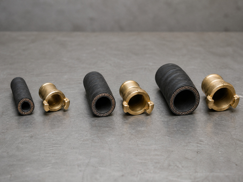
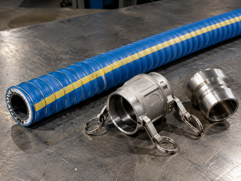
Figure 3. The lineup reads left to right: bore first, then the coupling built for it. The port thread comes from the plant.
Matching Steam Hose Couplings to the Duty and the Order
Start with the system, not the catalog. The duty sets the family, and the duty is fixed by the maximum pressure the system can deliver together with the steam condition at the point of use. The bore sets the coupling. The port sets the thread form and size.
The steam condition matters because pressure and temperature travel together. A coupling chosen for a pressure figure alone, without the matching temperature, is only half specified. Our saturated steam hose guide explains why one number always implies the other.
Two questions about steam hose couplings then decide the order: which family the duty allows, and which thread the port carries. The first is answered by the permitted list above, and the second by the port itself rather than by preference.
Each end is chosen on its own: the port end takes the family the port allows, and the hose end takes a crimp or a clamp, so one assembly often carries two families.
Where a line is broken and remade often, the permitted answer is the ground joint, drawn up by hand on its hammer lug and checkable again after each heat cycle.
Table 5. Matching a coupling choice to the way the steam line is used.
| How the line is used | Coupling family that fits | What to confirm | Who specifies it |
|---|---|---|---|
| Utility station, moved often | Ground joint with an interlocking clamp | That the parts belong to one coupling family | Maintenance fitter |
| Fixed process take-off | Threaded end at the port | That thread form and size match the port | Project engineer |
| Large fixed connection | Flanged end on a mating flange | That the flange standard and gasket match | Piping engineer |
| Factory-built assembly | Crimped ferrule at both ends | That the assembly is rated at its lowest part | OEM buyer |
| Serviceable field assembly | Bolted safety clamp on the shank | That the clamp can be re-torqued to specification | Maintenance planner |
Whatever family is chosen, fit a whip check or safety cable at every connection so a released end cannot swing. Beyond that, the inspection sequence belongs with steam hose inspection, not with the selection.
A selection is finished when the family, the bore, the thread and the assembly method all agree, and when the lowest-rated component rule has been applied to the finished parts list. Anything short of that leaves a gap between the hose rating and the assembly rating.
Steam Hose Coupling FAQs
Which coupling types are allowed on steam?
Permitted families are the ground joint or Boss coupling, threaded ends, flanged ends, permanent crimped ferrules, and bolted or interlocking clamp-type ends. Each one seals in a way that tolerates hot water and can be monitored over time. Quick-release ends and general-purpose clamps fall outside that list.
Can I use an NPT coupling in a BSPT port?
No. NPT and BSPT are both tapered threads, but they differ in thread angle, pitch and taper diameter, so an NPT male does not seat along the flanks of a BSPT female. A few turns will feel like engagement, and then the joint weeps or strips. Match the thread system, not only the size.
How do I read a coupling size chart for a steam hose?
Read the coupling size chart by band rather than by size alone. The bore places the assembly in a band, the coupling size names the part built for that bore, and the port thread names the system. The band limits which end connections exist at that bore. A match on bore alone is not enough, because the port decides the thread.
Why is a quick-release coupling prohibited on steam?
Steam holds far more stored energy than air or water at the same pressure. A cam and groove end releases on a small movement of its cam arms, which heat, vibration or a pressure shock can produce. ISO 6134:2024 prohibits quick-release ends by name, so a sudden release cannot be accepted.
Should a steam hose be crimped or clamped?
Both approaches have a place. A crimped ferrule is permanent, reduces leak paths and suits a factory-built assembly with fixed ends. A bolted clamp can be re-tightened to compensate for rubber creep after heat cycles, which some operators prefer on a serviceable line. Whichever is chosen, the assembly rating stays at the lowest-rated component.
What thread form should I order for a steam connection?
Order the thread system the mating port uses, whether that is NPT, BSPT or a parallel form. Confirm the form, the nominal size and the system together, because a size alone does not define a sealing pair. A thread standard check before ordering catches a mismatched pair that a size match would hide.
Do I need a hammer lug on a ground joint coupling?
A hammer lug is the wrenching feature on the swivel female of a ground joint coupling. It lets the nut be drawn up against the spud with a hammer or a wrench while the hose side stays fixed. Hand-tight seating is the aim, and the lug simply gives the leverage to reach it.
How often should the couplings be checked?
Check the couplings before the assembly goes into service, and at least once every 24 hours during long periods of continuous steaming. Inspect for loose fittings, extruded rubber, a bolt that has lost its torque and any visible steam leak. Re-tighten clamp-type ends after the first heat cycles.
Does the coupling rating change the assembly rating?
Yes. The hose rating is set by the hose maker under a defined test, and a finished assembly takes the lowest rating among the hose, the coupling, the clamp and the attachment method. The NAHAD guidelines state this as the lowest-rated component rule, so a high coupling rating cannot lift an assembly above its weakest part.
About HENGHUA and Steam Coupling Supply
HENGHUA manufactures steam hose, industrial hose and hydraulic hose for plants, distributors and equipment builders worldwide. The steam range uses an EPDM construction with a high-tensile steel wire braid or textile reinforcement and an evenly pin-pricked cover, so gas that permeates the wall can vent instead of lifting the cover.
On the fittings side we supply steam hose couplings across the ground joint (Boss) family, with bolted safety clamps and clamp-type end connections to match. Assemblies can be factory-crimped or built with clamps and matching tails, and custom lengths, cover printing, private label and OEM/ODM work are all available.
Published figures for the high-pressure construction are a 250 psi (17 bar) working pressure and a 2,500 psi (170 bar) burst pressure, a ten to one ratio. Two things we tell buyers plainly: an end connection has to suit steam rather than a headline pressure, and an assembly is only as good as its weakest part.
If you know the bore, the length, the working pressure, the steam condition and the port thread, send us those five data points. We will confirm the product and the end connection, and we will say so when a duty belongs to another family instead. Please get a quote and free samples, or review the steam hose category.
About the author: Written by the HENGHUA Engineering Team, hose application engineers and assembly specialists supporting hose selection, end connections and pressure testing for industrial, marine, food processing and mobile equipment customers. The coupling and thread limits here reflect our production and field service experience with steam hose assemblies, together with the pressure testing and batch traceability records held for every shipment.

 English
 Spanish
 Portuguese
 French
 German
 Arabic
 Russian
 Indonesian
 Japanese
 Korean