
The five hydraulic fitting types you will meet on almost every machine — JIC, ORFS, NPT, BSP, and metric (DIN/ISO) — are separated by two things only: the thread form and the point at which the joint actually seals.
JIC seals on a 37° metal flare, ORFS on an O-ring held against a flat face, NPT and BSPT on a tapered thread that wedges into the port, BSPP on a washer or elastomer seal under the hex, and metric DIN/ISO fittings on a 24° cone, a cutting ring, or a straight-thread O-ring boss.
This guide explains each hydraulic fitting type in the order a technician actually needs it — how it seals, its thread size and dash number, its working pressure, how to identify it with a caliper and a thread gauge, which standards can be joined with an adapter, where each one is used, and the torque and assembly mistakes that cause most leaks we see in service.
If you only have time for one rule, take this one: identify the port standard first, then the size. Thread diameter alone never identifies a fitting — a 1/2-inch NPT male, a 1/2-inch BSPT male, and a JIC -8 male are three different joints, and only one of them will seal in the port in front of you.
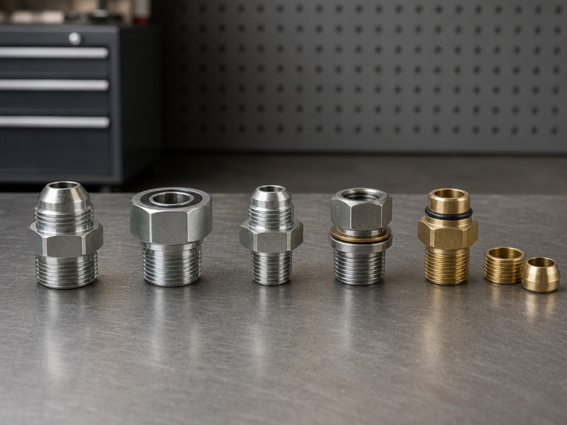
The five fitting families side by side: JIC, ORFS, NPT, BSP and metric fittings, with the adapters that join them.
The Short Answer: What Separates the Five Hydraulic Fitting Types
Start Here: What to Read First, Depending on What You Are Holding
Table 1a. Where to start in this guide, by reader
| If you are… | Read first | Have ready |
|---|---|---|
| On the machine with the fitting in hand | The five-step identification method, then Table 9 and Table 10 | A caliper, a pitch gauge and a photograph of the port |
| Specifying a new build | The Short Answer, then What Pressure Can Each Hydraulic Fitting Type Take? and Choosing a Standard for a New System | The pump, valve and cylinder port types, and the working pressure including surge |
| Buying or quoting | Table 9 (cross-standard chart), Table 3b (torque) and the Final Verdict list | Family, dash size, material and annual volume |
| Machine down and chasing a leak | The failure table (Table 15) and the safety block first | The symptom, the fluid temperature and the fitting you removed |
Every hydraulic fitting type is defined by four properties, and a fitting is only correct when all four match the port and the hose: thread form (parallel or tapered, inch or metric), thread angle and pitch, seal mechanism (flare, O-ring, washer, cone, or tapered thread), and size — hydraulic fitting sizes are quoted as a dash number or a metric thread size. Get the seal mechanism wrong and the joint leaks no matter how hard you tighten it; get the thread form wrong and the parts will not mate at all without damaging metal.
A second axis matters as much as the first: where the seal is made. Metal-to-metal flare seals (JIC) depend on surface condition and torque. Elastomer seals (ORFS, the O-ring boss or ORB — SAE J1926 / ISO 11926 —, ISO 6149, BSPP with a bonded washer) depend on the seal being present, clean, and undamaged. Tapered-thread seals (NPT, NPTF, BSPT) depend on interference between the threads themselves — which is also why they relax under vibration.
Table 1. The five hydraulic fitting types, plus the straight-thread port standard they connect to, and how each one seals
| Fitting type | Thread form | Thread angle | Where it seals | Dominant market | Typical maximum working pressure |
|---|---|---|---|---|---|
| JIC (SAE J514) | Parallel UNF | 60° | 37° metal flare seat | North America | Up to ~6,000 PSI (414 bar) in the smallest sizes, down to ~3,000 PSI (207 bar) at -16 and above |
| ORFS (SAE J1453) | Parallel UNF | 60° | O-ring on a flat face | North America, high-vibration duty | Up to ~6,000 PSI (414 bar) |
| NPT / NPTF (ASME B1.20.1) | Tapered pipe thread | 60° | Thread interference | North America, legacy and static lines | Up to ~3,000 PSI (207 bar) |
| BSPP / BSPT (ISO 228-1 / ISO 7-1) | Parallel / tapered | 55° | Washer or elastomer face; thread interference for BSPT | UK, Europe, Asia-Pacific | ~5,000 PSI (345 bar) in common sizes |
| Metric DIN 2353 (ISO 8434-1) | Metric straight thread | 60° | 24° cone with cutting ring or O-ring | Europe | ~315 bar (4,600 PSI) in the L series to 630 bar (9,100 PSI) in the S series |
| Metric ISO 6149 / SAE J1926 (ORB) | Metric or inch straight thread | 60° | O-ring under the hex, at the port chamfer | Component ports worldwide | Up to ~6,000 PSI (414 bar) |
Pressure figures are typical published ratings for steel fittings and fall as bore size increases. Bar values are arithmetic conversions of the published PSI figures (1 PSI = 0.0689 bar). The rating for a specific part always comes from that manufacturer’s data sheet.
The rest of this guide works through each hydraulic fitting type in turn, then compares them size by size, walks through identification with two inexpensive tools, and sets out which standards can be connected to which — with an adapter rather than by force.
Why Hydraulic Fitting Types Do Not Interchange
The reason hydraulic fittings refuse to mate is standardization. Every dimension is fixed by a published standard: SAE J514 for the 37° flare, SAE J1453 for O-ring face seal, SAE J1926 and ISO 11926 for straight-thread O-ring boss ports, ISO 8434-1 and DIN 2353 for the 24° cone, ISO 228-1 and ISO 7-1 for British pipe threads, and ASME B1.20.1 for NPT. A fitting built to one standard will not seal in a port built to another, even when both are described as the same nominal size.
The practical consequence is that “half inch” is not a specification. A 1/2-inch NPT male measures about 0.84 inch across the threads, a 1/2-inch BSPT male measures about 0.82 inch, and a JIC -8 male uses a 3/4-16 thread. Two of those three measure within two hundredths of an inch of each other and will start to thread into the wrong port — which is exactly how ports get ruined.
The Two Questions That Identify Any Fitting
Before any measurement, answer two questions and the candidate list shrinks from dozens to a handful.
- Is the thread parallel or tapered? Run a caliper across the threads near the nose, then near the hex. If the diameter grows, it is a tapered pipe thread — NPT, NPTF, or BSPT. If it holds steady, it is a parallel thread — JIC, ORFS, ORB, BSPP, or a metric straight thread.
- Where is this joint designed to seal? Look for the seal feature, not the thread: a 37° cone seat (JIC), an O-ring in a flat face (ORFS), an O-ring under the hex (ORB or ISO 6149), a washer face under the hex (BSPP), a 24° cone with a cutting ring (DIN 2353), or nothing at all but the threads themselves (NPT, NPTF, BSPT).
Those two answers take about thirty seconds with the fitting in your hand, and they eliminate the failure mode that causes most return shipments: buying a fitting that screws on but cannot seal.
Thread Angle: Why 55° and 60° Cannot Be Mixed
Inch Unified threads, NPT pipe threads, and metric threads are all 60° forms. British Standard Pipe threads are 55°. That single degree-and-a-half difference is invisible to the eye and decisive in service: a 1/2-inch BSPT and a 1/2-inch NPT share the same 14 threads per inch and almost the same diameter, so a BSPT male will wind a turn or two into an NPT port before it binds. It will then leak, and forcing it further deforms both thread sets. There is a dedicated comparison in our Guide des filetages NPT et BSP if you need to settle that question before ordering.
JIC Fittings (SAE J514): The 37° Flare Standard
JIC — Joint Industry Council — fittings seal on a 37° flare: the male end carries an external 37° seat, the female end an internal 37° cone, and a straight UNF thread draws the two seats together until metal meets metal. JIC is the most widely used hydraulic fitting type in North America and the default connection on mobile and agricultural equipment, general industrial machinery, and any system built to SAE conventions.
Because the seal is metal-to-metal, three things decide whether a JIC joint holds: the condition of the two seats, the alignment of the parts, and the torque applied to the swivel nut. A scored or corroded flare seat leaks even when the threads are perfect, which is why the seats — not the threads — are the first thing to inspect on a leaking JIC connection.
JIC Thread Sizes and Dash Numbers
JIC sizes follow the dash system, where the dash number is the nominal size in sixteenths of an inch. The table below gives the thread and the measured thread diameters, so a caliper reading can be matched directly.
Table 2. JIC 37° flare (SAE J514) thread sizes by dash number
| Taille des tirets | Diamètre nominal (pouces) | Thread size (UNF) | Male thread OD (in) | Female thread ID (in) |
|---|---|---|---|---|
| -2 | 1/8 | 5/16-24 | 0.31 | 0.27 |
| -3 | 3/16 | 3/8-24 | 0.38 | 0.34 |
| -4 | 1/4 | 7/16-20 | 0.44 | 0.39 |
| -5 | 5/16 | 1/2-20 | 0.50 | 0.45 |
| -6 | 3/8 | 9/16-18 | 0.56 | 0.51 |
| -8 | 1/2 | 3/4-16 | 0.75 | 0.69 |
| -10 | 5/8 | 7/8-14 | 0.88 | 0.81 |
| -12 | 3/4 | 1 1/16-12 | 1.06 | 0.98 |
| -14 | 7/8 | 1 3/16-12 | 1.19 | 1.10 |
| -16 | 1 | 1 5/16-12 | 1.31 | 1.23 |
| -20 | 1 1/4 | 1 5/8-12 | 1.63 | 1.54 |
| -24 | 1 1/2 | 1 7/8-12 | 1.88 | 1.79 |
| -32 | 2 | 2 1/2-12 | 2.50 | 2.42 |
Dash size names two different things, and the difference decides whether a part fits. For hose, the dash number is the nominal bore in sixteenths of an inch: a -8 hose has a 1/2 inch (12.7 mm) bore. For fittings, the dash number indexes the thread size: a -8 JIC end is a 3/4-16 thread. The two -8 figures are related by convention, not by value. The threads in the table are what the caliper should read on a JIC fitting, within a manufacturing tolerance of a few thousandths of an inch on the outside diameter. To read the bore side of the same dash number, use our how to measure a hydraulic hose guide.
JIC vs AN, and JIC vs the 45° SAE Flare
Two comparisons inside this family list cause more confusion than any others.
JIC and AN. Both use a 37° seat and the two seat angles are identical, so an AN hose end will usually seal against a JIC flare — but the threads are not the same series. AN fittings use UNJ threads with a controlled root radius; JIC uses standard UNF. In practice they are treated as incompatible for anything but emergency field use, and mixing them in a certificate-bound system is not defensible.
JIC and the 45° SAE flare. SAE J512 uses a 45° seat and appears on fuel, refrigerant, and automotive lines. Some sizes share the same thread as JIC — the -4 is 7/16-20 in both — so a 45° fitting screws onto a 37° flare and looks assembled. It will leak, because the seat angles cannot touch along their full width. If a joint threads up but will not seal dry, measure the seat angle before you apply more torque.
Assembling a JIC Joint: Torque, Seating, and Three Common Mistakes
JIC wants to be tightened enough to seat the flare and no more. The table below gives typical swivel-nut torque for zinc-plated steel fittings — confirm against your fitting manufacturer’s table, because plating, lubrication, and material change the number.
Table 3. Typical JIC swivel-nut assembly torque for steel fittings
| Taille des tirets | Thread | Typical torque (N·m) | Typical torque (ft-lb) |
|---|---|---|---|
| -4 | 7/16-20 | 12-14 | 9-10 |
| -6 | 9/16-18 | 20-27 | 15-20 |
| -8 | 3/4-16 | 40-47 | 30-35 |
| -10 | 7/8-14 | 55-60 | 40-44 |
| -12 | 1 1/16-12 | 75-80 | 55-60 |
| -16 | 1 5/16-12 | 105-110 | 78-81 |
Three mistakes account for most JIC leaks we inspect. Over-torquing, which crushes the flare nose and cracks the seat. Reusing a joint after it has been run hot and then re-torquing it hard, which work-hardens the flare. And assembling with the hose under twist, which loads the flare sideways so it never seats evenly. In our own shop, a correctly torqued JIC joint held 5,000 PSI with no measurable leak across a 60-second soak, while the same joint assembled with the hose twisted showed seepage in under a minute — the difference was alignment, not parts.
ORFS Fittings (SAE J1453): O-Ring Face Seal Explained
ORFS — O-ring face seal — seals with an elastomer O-ring trapped between two flat faces. The threads are straight and parallel; they exist only to clamp the faces together. Because the seal no longer depends on metal deformation or on torque deforming a seat, ORFS tolerates re-assembly, vibration, and pressure cycling better than any metal-to-metal type, and it is the standard answer on high-impulse circuits: excavator booms, mining equipment, and hydraulic systems that are serviced repeatedly.
The trade-off is honesty about what it needs. An ORFS joint with a nicked O-ring, a scratched face, or contamination on the sealing face will leak regardless of how well it is tightened, and tightening harder only deforms the faces. Seal condition is the whole joint.
ORFS Thread Sizes
ORFS starts at -4 and its threads are noticeably larger than JIC threads of the same dash size — the reason the two families are never confused once measured.
Table 3b. Typical ORFS swivel-nut assembly torque for zinc-plated steel fittings (dry threads; the fitting manufacturer’s table for the exact part governs)
| Taille des tirets | Thread | Typical torque (N·m) | Typical torque (ft-lb) |
|---|---|---|---|
| -4 | 9/16-18 | 19-22 | 14-16 |
| -6 | 11/16-16 | 24-27 | 18-20 |
| -8 | 13/16-16 | 43-48 | 32-35 |
| -10 | 1-14 | 57-62 | 42-46 |
| -12 | 1 3/16-12 | 81-88 | 60-65 |
| -16 | 1 7/16-12 | 129-136 | 95-100 |
| -20 | 1 11/16-12 | 170-190 | 125-140 |
Table 4. ORFS (SAE J1453) thread sizes by dash number
| Taille des tirets | Diamètre nominal (pouces) | Thread size (UNF) | Male thread OD (in) | Female thread ID (in) |
|---|---|---|---|---|
| -4 | 1/4 | 9/16-18 | 0.56 | 0.51 |
| -6 | 3/8 | 11/16-16 | 0.69 | 0.63 |
| -8 | 1/2 | 13/16-16 | 0.82 | 0.75 |
| -10 | 5/8 | 1-14 | 1.00 | 0.93 |
| -12 | 3/4 | 1 3/16-12 | 1.19 | 1.11 |
| -16 | 1 | 1 7/16-12 | 1.44 | 1.36 |
| -20 | 1 1/4 | 1 11/16-12 | 1.69 | 1.61 |
| -24 | 1 1/2 | 2-12 | 2.00 | 1.92 |
ORFS vs JIC: How to Choose
The JIC versus ORFS decision is about duty, not about a single pressure number. Carbon steel JIC fittings are typically published from about 6,000 PSI in the smallest sizes and fall to roughly 3,000 PSI at -16 and above, while ORFS holds about 6,000 PSI across the same dash sizes. Read the figure for your exact size from the data sheet, because the choice is made by how the machine is used rather than by the pressure label alone.
- Choose ORFS where the circuit sees continuous impulse, where the joint is broken and remade during service, or where a weep is unacceptable — mining, offshore, high-cycle mobile equipment.
- Choose JIC where the ports are already JIC, where cost and availability decide, and on moderate-pressure lines that are assembled once and left alone.
- Join the two with an adapter. An ORFS female seals only on a flat face, so a JIC flare has nothing to seat against: use an adapter, because a cross-family joint can pass a visual check and still leak under pressure.
For the commercial half of the same decision — identification at the bench, seal materials, cost bands, a supplier checklist and a quote template — see our hydraulic hose fittings identification and selection guide.
If your circuit mixes JIC and ORFS ports, send us the port on each end and the working pressure, and our engineers will confirm the adapter and the assembly in one reply.
One more honest limitation: ORFS needs face clearance. In a manifold where ports sit close together, the larger ORFS hex and nut can foul a neighbouring fitting — a packaging constraint that JIC usually avoids.
O-Ring Care, Torque, and Reuse Rules
An ORFS nut is tightened to the published torque band for its own thread size, because the nut only has to compress the O-ring and hold the two faces in contact. The bands in Table 3b are for zinc-plated steel fittings with clean, dry threads and are given in both units; the table sits beside Table 3 so the two torque tables can be compared directly because a torque wrench is usually marked in only one of them.
Three conditions keep an ORFS torque value valid. The figure moves with plating, lubrication and material, so the fitting maker’s table for the exact part is the binding one. JIC and ORFS of the same dash size do not share a torque value, because both the thread and the sealing mechanism differ. And a torque wrench used on a swivel nut needs to react against the mating half, not against the hose.
Three rules keep an ORFS fitting dry. Fit a new O-ring at every re-make: a heat-cycled O-ring has taken a compression set and will not seal reliably again. Assemble the threads dry, because lubrication changes the torque-to-preload relationship. Clean the sealing faces with a lint-free cloth and a soft brush, and keep a wire brush away from them. In our in-house impulse testing, ORFS joints held zero leak after 1,000,000 cycles at 4,000 PSI — the same construction that failed first in our vibration bench was always the one with a reused O-ring rather than a new one.
NPT and NPTF Fittings: Tapered Pipe Threads
NPT (National Pipe Taper) is a 60° tapered pipe thread that seals by interference: the male and female threads wedge together along a 1-in-16 taper, and the seal is made by the threads themselves. An NPT fitting therefore depends entirely on thread engagement for its seal, which is the root of its weakness in hydraulic service. NPTF — the “fuel” or dryseal variant — is machined to tighter tolerances so that the crest of one thread crushes into the root of the other and seals without any compound. Both are everywhere in fluid piping, and both are the weakest choice for hydraulic impulse service.
Treating tapered pipe threads as an impulse-duty connection is an industry practice rather than a fixed standard requirement, and the reason shows up quickly on a test bench: under pressure cycling and vibration, a tapered joint relaxes, the interference that made the seal disappears, and the connection begins to weep. In our own vibration test, the same size NPT joint loosened roughly half a turn within 200 pressure cycles while an equivalent JIC joint stayed dry.
NPT Thread Sizes and Thread Counts
NPT is sized by pipe size, not by hole size — a 1/2-inch NPT thread measures about 0.84 inch outside diameter. Note also that the threads-per-inch count changes with size, which is why a pitch gauge is part of any identification kit.
Table 5. NPT / NPTF thread sizes by dash number
| Pipe size (in) | Taille des tirets | Threads per inch | Male thread OD (in) | Female thread ID (in) |
|---|---|---|---|---|
| 1/8 | -2 | 27 | 0.41 | 0.38 |
| 1/4 | -4 | 18 | 0.54 | 0.49 |
| 3/8 | -6 | 18 | 0.68 | 0.63 |
| 1/2 | -8 | 14 | 0.84 | 0.77 |
| 3/4 | -12 | 14 | 1.05 | 0.98 |
| 1 | -16 | 11.5 | 1.32 | 1.24 |
| 1 1/4 | -20 | 11.5 | 1.66 | 1.58 |
| 1 1/2 | -24 | 11.5 | 1.90 | 1.82 |
| 2 | -32 | 11.5 | 2.38 | 2.30 |
Sealants, Tape, and Torque on NPT Joints
When an NPT fitting is the only option — a static gauge port, a filter housing, a legacy machine — the assembly rules differ from every other hydraulic fitting type in this guide.
- Use a hydraulic-grade thread sealant, not PTFE tape. Tape fragments migrate into valve spools and pump inlets; a liquid anaerobic or paste sealant does not shed. Apply it to the male threads only, leaving the first two threads bare.
- Assemble NPTF dryseal joints bare. The crest of one thread is machined to crush into the root of the other, so metal-to-metal contact is what makes that seal, and tape under the threads changes the engagement it depends on.
- Tighten by feel, not by force. NPT joints are normally made up “wrench-tight plus a quarter to a half turn”, and the correct stopping point is when the joint stops turning freely. Continuing past that point splits ports and cracks housings.
- Bridge standards with an adapter machined for both ends. An NPT male forced into a BSPT female, or into a JIC port through a bushing, deforms both thread sets instead of sealing them.
If a machine’s ports are NPT and the circuit runs hot and shock-loaded, the correct engineering answer is a port adapter to JIC, ORFS, or ORB — not a tighter pipe joint.
BSP Fittings: BSPP and BSPT (G and R Threads)
BSP is the British Standard Pipe family, and it is the dominant thread system in the UK, across much of Europe, and in a large part of Asia-Pacific. It splits into two forms that behave completely differently.
BSPP (parallel, designated G) has a constant diameter and seals on an elastomeric washer or bonded seal trapped under the hex, or on a metal cone seat in swivel designs. The threads carry load only. This is why wrapping BSPP threads in tape achieves nothing: there is no tapered interference to seal, and a BSP fitting is identified by what sits under the hex rather than by the thread alone.
BSPT (tapered, designated R) seals the way NPT does — by thread interference along a 1-in-16 taper. It is common on older European and Japanese machinery and on some imported pumps and valves.
BSP Thread Sizes and Identification
Table 6. BSPP (G) and BSPT (R) thread sizes by dash number
| Pipe size (in) | Taille des tirets | Thread size | Male thread OD (in) | Female thread ID (in) |
|---|---|---|---|---|
| 1/8 | -2 | 1/8-28 | 0.38 | 0.35 |
| 1/4 | -4 | 1/4-19 | 0.52 | 0.47 |
| 3/8 | -6 | 3/8-19 | 0.65 | 0.60 |
| 1/2 | -8 | 1/2-14 | 0.82 | 0.75 |
| 5/8 | -10 | 5/8-14 | 0.90 | 0.81 |
| 3/4 | -12 | 3/4-14 | 1.04 | 0.97 |
| 1 | -16 | 1-11 | 1.30 | 1.22 |
| 1 1/4 | -20 | 1 1/4-11 | 1.65 | 1.56 |
| 1 1/2 | -24 | 1 1/2-11 | 1.88 | 1.79 |
| 2 | -32 | 2-11 | 2.35 | 2.26 |
NPT vs BSP: The 55° and 60° Trap
This is the single most damaging mismatch in hydraulic fitting identification, because the two families are close enough to start, and far enough apart to fail.
- Thread angle. NPT is 60°, BSP is 55°. No gauge-free visual check will separate them reliably.
- Thread count. A 1/2-inch NPT and a 1/2-inch BSPP are both 14 threads per inch. The diameters differ by only about 0.02 inch.
- Behaviour. A BSP fitting with a tapered thread will enter an NPT port a turn or two, feel “almost right”, then bind. Tightening it further distorts both thread forms, and the port is scrap.
- The reliable test. A thread pitch gauge confirms the count and a thread angle gauge confirms 55° versus 60°. Match the caliper reading against the chart before you order: an OD of 0.82 inch (21.0 mm) with 14 TPI is BSPP, an OD of 0.81 inch (20.6 mm) with 16 TPI is ORFS -8, and an OD of 0.84 inch with 14 TPI is NPT. That margin of a few hundredths of an inch is measurable with a digital caliper, which is why the gauge rather than the eye makes the call.
A further caution: BSPP male fittings resemble the American NPSM straight mechanical thread, but the pitch differs, so they are not interchangeable either.
Metric Hydraulic Fittings: DIN 2353, ISO 6149, and JIS 30°
Metric hydraulic fittings are three separate connection systems, each with its own seal mechanism, and confusing them is where most identification errors with European and Japanese machinery begin: the DIN 2353 / ISO 8434-1 24° cone tube fitting, the ISO 6149 straight-thread O-ring port, and the Japanese JIS (Japanese Industrial Standards) 30° flare family, including the metric Komatsu pattern. Thread size and pitch identify the size; only the seal feature identifies the system, which is why a metric hydraulic fitting cannot be ordered from a thread measurement alone.
DIN 2353 and ISO 8434-1: The 24° Cone System
DIN 2353 is the classic European tube fitting: a 24° cone on the male half seals against the female cone, and the tube is gripped either by a cutting ring that bites into the tube wall or, in the soft-seal versions, by an elastomeric seal. It comes in two series that must not be substituted for each other: light (L) series for lower pressures and heavy (S) series for high-pressure work. The same nominal tube size can appear in both series with a different thread.
Table 7. DIN 2353 light (L) and heavy (S) series — tube sizes, threads and pitch
| Tube OD, L series (mm) | Tube OD, S series (mm) | Thread size | Pitch (mm) |
|---|---|---|---|
| 6 | — | M12 x 1.5 | 1.5 |
| 8 | 6 | M14 x 1.5 | 1.5 |
| 10 | 8 | M16 x 1.5 | 1.5 |
| 12 | 10 | M18 x 1.5 | 1.5 |
| — | 12 | M20 x 1.5 | 1.5 |
| 15 | 14 | M22 x 1.5 | 1.5 |
| — | 16 | M24 x 1.5 | 1.5 |
| 18 | — | M26 x 1.5 | 1.5 |
| 22 | 20 | M30 x 2.0 | 2.0 |
| 28 | 25 | M36 x 2.0 | 2.0 |
| — | 30 | M42 x 2.0 | 2.0 |
| 35 | — | M45 x 2.0 | 2.0 |
| 42 | 38 | M52 x 2.0 | 2.0 |
On pressure, the honest answer is that the rating depends on the series and the tube size, not on the thread. Light series fittings are generally rated in the 250-315 bar band in small tube sizes, and heavy series fittings reach about 630 bar in small sizes, with both falling as tube diameter rises. Take the rating for your exact size from the manufacturer’s catalogue rather than reading it off the thread.
ISO 6149 Metric O-Ring Ports
ISO 6149 is the metric twin of the SAE straight-thread O-ring boss: a straight metric thread with an O-ring under the hex that seals against a chamfer in the port. It is common on European pumps, valves, and manifolds, and its most common field error is being treated as interchangeable with DIN 2353 because both use metric threads. They are not: one seals on a cone with a cutting ring, the other on an O-ring at the port face.
Table 8. ISO 6149 metric straight-thread O-ring ports — the common sizes are listed; a metric thread size that is not in this table can still belong to the standard
| Metric thread size | Male thread OD (mm) | Female thread ID (mm) |
|---|---|---|
| M12 x 1.5 | 12 | 10.5 |
| M14 x 1.5 | 14 | 12.5 |
| M16 x 1.5 | 16 | 14.5 |
| M18 x 1.5 | 18 | 16.5 |
| M22 x 1.5 | 22 | 20.5 |
| M27 x 2.0 | 27 | 25 |
| M33 x 2.0 | 33 | 31 |
| M42 x 2.0 | 42 | 40 |
| M48 x 2.0 | 48 | 46 |
JIS 30° Flare and the Komatsu Pattern
Japanese machinery adds a further distinction: two different systems share a 30° seat and are regularly confused. The JIS 30° flare uses a 30° seat with BSPP-like thread dimensions, so it measures like a British pipe thread but seals nothing like one. The Komatsu 30° flare pattern uses parallel metric threads with the same 30° seat. Neither is a DIN 2353 fitting: a Komatsu -6 is M18 x 1.5, while a DIN 2353 light-series 10 mm tube takes M16 x 1.5. The Komatsu pattern appears in dash sizes from -6 to -24: M18 x 1.5 (-6), M22 x 1.5 (-8), M24 x 1.5 (-10), M30 x 1.5 (-12), M33 x 1.5 (-16), M36 x 1.5 (-20), and M42 x 1.5 (-24). Neither family is compatible with a JIC 37° flare, even when the diameters are close.
Metric vs Inch: The First Branch in Identification
Before measuring anything, decide whether the fitting is inch or metric, because that decision eliminates half the possibilities at once.
- Inch systems use dash numbers (-4, -6, -8, -12) and thread counts expressed as threads per inch.
- Metric systems use a millimetre nominal thread size with a pitch in millimetres (M14 x 1.5, M18 x 1.5, M22 x 1.5) and no dash number at all.
- The classic metric-versus-inch error is that a JIC -6 (9/16-18, OD 0.56 in / 14.2 mm) and a DIN M14 x 1.5 (OD 14 mm) are within two-tenths of a millimetre of each other in diameter, and a technician with only a caliper will call them the same size. The thread pitch gives them away: 18 threads per inch is a 1.41 mm pitch, while M14 x 1.5 is a 1.5 mm pitch.
Hydraulic Fitting Types Chart: How Do the Five Standards Compare by Dash Size?
One dash number reads across all five fitting standards, and the two things it cannot tell you are the thread angle and the seal type. This hydraulic fitting types chart places the hydraulic fitting sizes of JIC, ORFS, NPT, BSP and DIN 2353 side by side in the size range that covers most equipment, so a single caliper reading can be matched to a standard in one look. Print it, or save it as a PDF, and keep it on the bench.
Table 9. Hydraulic fitting sizes chart: the five fitting standards compared by dash size — the DIN 2353 column gives the nearest tube outside diameter in the light (L) or heavy (S) series, not an equivalent bore
| Taille des tirets | JIC 37° flare (UNF) | ORFS (UNF) | NPT pipe thread | BSPP / BSPT | DIN 2353 nearest tube / thread |
|---|---|---|---|---|---|
| -2 | 5/16-24 | — | 1/8-27 | 1/8-28 | — |
| -4 | 7/16-20 | 9/16-18 | 1/4-18 | 1/4-19 | 6 mm / M12 x 1.5 |
| -6 | 9/16-18 | 11/16-16 | 3/8-18 | 3/8-19 | 10 mm / M16 x 1.5 |
| -8 | 3/4-16 | 13/16-16 | 1/2-14 | 1/2-14 | 12 mm / M18 x 1.5 |
| -10 | 7/8-14 | 1-14 | — | 5/8-14 | 15 mm / M22 x 1.5 |
| -12 | 1 1/16-12 | 1 3/16-12 | 3/4-14 | 3/4-14 | 18 mm / M26 x 1.5 |
| -16 | 1 5/16-12 | 1 7/16-12 | 1-11.5 | 1-11 | 25 mm / M36 x 2.0 |
| -20 | 1 5/8-12 | 1 11/16-12 | 1 1/4-11.5 | 1 1/4-11 | 30 mm / M42 x 2.0 |
| -24 | 1 7/8-12 | 2-12 | 1 1/2-11.5 | 1 1/2-11 | 38 mm / M52 x 2.0 |
Note on the metric column: a 1/2 inch (-8) hose has a 12.7 mm nominal bore. The nearest DIN 2353 tube outside diameters are 12 mm in the light (L) series, which carries an M18 x 1.5 thread, and 10 mm in the heavy (S) series, which carries the same M18 x 1.5 thread. The metric figure in this chart is the nearest tube size in either series, not an equivalent bore, so confirm the metric equivalent against the tube the fitting connects to; Table 7 gives the full L and S mapping.
Table 9 shows two patterns that matter at the bench. First, ORFS threads are consistently one size larger than JIC threads of the same dash number — a -8 JIC is 3/4-16 while a -8 ORFS is 13/16-16 — so a caliper separates them immediately. Second, BSP and NPT threads of the same nominal pipe size sit only hundredths of an inch apart, so they cannot be separated by diameter alone. Dash size alone is never enough: the standard must be confirmed with a pitch or angle gauge.
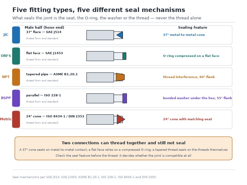
Figure 1. The seal point, not the thread, defines the fitting type. From left: JIC 37° flare, ORFS O-ring face, NPT tapered thread, BSPP washer seal, and DIN 2353 24° cone with cutting ring.
How to Identify Hydraulic Fitting Types in Five Steps
Hydraulic fitting identification needs two inexpensive tools — a digital caliper and a thread pitch gauge — and about five minutes. It is the highest-value skill in hydraulic maintenance: a five-minute measurement prevents ordering against a port that costs far more to replace than the fitting.
- Measure the thread outside diameter. On a male fitting, measure across the thread crests with the caliper. Compare the reading with the hydraulic fitting sizes in Table 9 or with the single-standard tables above. Work in both inches and millimetres if the machine is imported.
- Check whether the thread is parallel or tapered. Measure the diameter at the nose and again near the hex. A change means a tapered pipe thread — NPT, NPTF, or BSPT. No change means a parallel thread, which rules out all three.
- Measure the pitch or thread count. Fit a pitch gauge to the male thread and find the leaf that seats across several crests: 18 TPI on a 0.56 inch thread is a JIC -6 (9/16-18), while a 1.5 mm reading at the same diameter is an M14 x 1.5. Pitch is what separates metric from inch at the boundary sizes.
- Identify the seal feature. A 37° seat means JIC. An O-ring in a flat face means ORFS. An O-ring under the hex means ORB or ISO 6149. A washer face means BSPP. A 24° cone with a cutting ring means DIN 2353. Nothing but a taper means NPT, NPTF, or BSPT.
- Confirm against the mating part or the port. The final check is the port itself: a matching seal feature on the port confirms the standard, and a port with a different seal feature confirms that an adapter — not force — is the answer.
Reading a Caliper Measurement Into a Standard
Table 10. Measured male thread outside diameter and the standards it can indicate
| Measured OD (in) | Possible standards | How to confirm |
|---|---|---|
| 0.38 (9.5 mm) | JIC -3 (3/8-24) | 37° flare seat; 24 TPI |
| 0.41 | NPT 1/8-27 | Taper present; 27 TPI |
| 0.44 | JIC -4 (7/16-20) or ORB -4 | 37° flare seat or O-ring under hex; 20 TPI |
| 0.50 | JIC -5 (1/2-20) or ORB -5 | Seat type; 20 TPI |
| 0.52 | BSPP / BSPT 1/4-19 | 55° thread angle; 19 TPI |
| 0.54 | NPT / NPTF 1/4-18 | Taper present; 18 TPI |
| 0.56 | JIC -6, ORB -6 (9/16-18), or ORFS -4 | Seat or O-ring face; 18 TPI; ORFS is a flat face |
| 0.65 | BSPP / BSPT 3/8-19 | 55° angle; 19 TPI |
| 0.68 | NPT / NPTF 3/8-18 | Taper; 18 TPI |
| 0.69 | ORFS -6 (11/16-16) | Flat face; 16 TPI |
| 0.75 | JIC -8 or ORB -8 (3/4-16) | Seat or O-ring under hex |
| 0.81 (20.6 mm) | ORFS -8 (13/16-16) | Flat face with a captive O-ring; 16 TPI |
| 0.82 (21.0 mm) | BSPP / BSPT 1/2-14 | 55° thread angle; 14 TPI; bonded washer under the hex |
| 0.84 | NPT / NPTF 1/2-14 | Taper present; 14 TPI |
| 0.88 (22.4 mm) | JIC -10 or ORB -10 (7/8-14) | 37° flare seat or O-ring under the hex; 14 TPI |
| 0.90 (22.9 mm) | BSPP / BSPT 5/8-14 | 55° thread angle; 14 TPI; bonded washer under the hex |
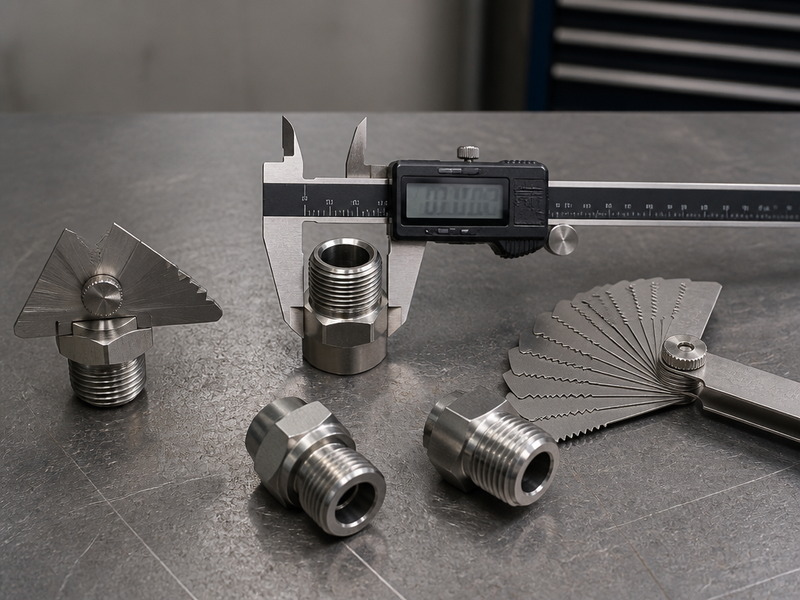
Figure 2. Two tools settle almost every hydraulic fitting identification question — a digital caliper for thread diameter and a pitch gauge for threads per inch or metric pitch — and a thread angle gauge settles the remaining 55° versus 60° cases.
When the Measurement Falls Between Two Threads
Manufacturing tolerance is real, and worn or plated threads will read slightly off nominal — commonly a few thousandths of an inch. Two situations are worth preparing for.
- The reading sits between a JIC and an ORFS size. Trust the seal feature: a flat face with an O-ring groove is ORFS, a 37° cone is JIC. Diameter alone cannot resolve this pair, because the sealing geometry is what separates them.
- The reading sits between an inch and a metric size. Trust the pitch gauge. A 9/16-18 JIC has a 1.41 mm pitch while an M14 x 1.5 has a 1.5 mm pitch, and the gauge will show which one matches.
Replace any fitting whose threads are visibly distorted, because a distorted thread cannot be identified reliably. Choose the part that threads on by hand and seats with a wrench: a fitting that has to be forced is already a leak path.
Send the caliper reading and a photograph of the port, and we will confirm the standard and the adapter before you order.
Hydraulic Fitting Seat and Thread Angles Compared: 24°, 30°, 37°, 45°, 55° and 60°
Every identification question above comes down to two angles and one measurement, and the angles are the part the thread tables cannot show. Table 11 collects the seat angles and thread angles used across the five standards, so a seat can be matched to a standard without working back through each section.
Table 11. Seat angles and thread angles across the hydraulic fitting standards, and whether each seals against a 37° JIC flare
| Seat type | Seat angle | Thread angle | Representative standard | Seals against a JIC 37° flare? |
|---|---|---|---|---|
| Metric cone with a cutting ring | 24° | 60° (metric) | DIN 2353 / ISO 8434-1 | No — different seat and series |
| Japanese flare (JIS) | 30° | 55°-class thread form | JIS B 8363 | No |
| Komatsu flare | 30° | 60° (metric) | Komatsu pattern | No |
| SAE flare (JIC) | 37° | 60° (UNF) | SAE J514 | Yes — this is the JIC seat |
| SAE 45° flare | 45° | 60° (UNF) | SAE J512 | No — threads can match, the seat cannot |
| BSP parallel with a bonded washer | Flat face, or a 60° internal cone | 55° (Whitworth) | ISO 228-1 | No |
| BSP taper | Thread interference | 55° (Whitworth) | ISO 7-1 | No |
| NPT / NPTF taper | Thread interference | 60° | ASME B1.20.1 | No |
| O-ring face seal | Flat face with a captive O-ring | 60° (UNF) | SAE J1453 | No |
| O-ring boss / straight-thread port | O-ring under the hex, at a port chamfer | 60° (UNF or metric) | SAE J1926 / ISO 6149 | No |
Two readings from Table 11 do most of the work. A cone is a cone only against its own angle, so a 45° SAE flare that threads onto a JIC -4 will not seal no matter how it is torqued. And a taper is a taper: NPT, NPTF and BSPT seal on thread interference, which is why they are the three families that relax under vibration.
TPI to Metric Pitch: Converting a Thread Reading Before You Order
A pitch gauge reads in threads per inch on one leaf and in millimetres on the other, and the two scales meet on the same fitting more often than the dash-size tables suggest. Divide 25.4 by the thread count to get the metric pitch, or read it off Table 12.
Table 12. Threads per inch converted to metric pitch (25.4 ÷ TPI)
| Threads per inch | Metric pitch (mm) | Where it appears |
|---|---|---|
| 11.5 | 2.21 | NPT 1 inch and above; BSPT 1 inch and above |
| 14 | 1.81 | NPT, BSPP and BSPT at 1/2 and 3/4 inch |
| 16 | 1.59 | ORFS -6 and -8 |
| 18 | 1.41 | JIC -6, ORB -6, NPT 1/4 and 3/8 |
| 19 | 1.34 | BSPP and BSPT 3/8 |
| 20 | 1.27 | JIC -4 and -5, ORB -4 |
| 24 | 1.06 | JIC -3 |
| 27 | 0.94 | NPT 1/8 |
| 28 | 0.91 | BSPP and BSPT 1/8 |
Pitch is what separates a metric thread from an inch thread that measures the same across the crests: 18 threads per inch is a 1.41 mm pitch while an M14 x 1.5 thread is a 1.5 mm pitch, and only a gauge tells them apart on a fitting held in the hand. The conversion is arithmetic (25.4 divided by the thread count), not a published standard figure.
Which Hydraulic Fitting Types Can Be Joined Directly, and Which Need an Adapter?
Different fitting families are joined by adapters, never by forcing one standard into another. An adapter introduces an extra interface, so the guiding principle is to use the fewest adapters that solve the problem, and to place them where they can be inspected.
Table 13. Joining different fitting families: what works, what needs an adapter, and what never to do
| Port / component thread | Line or hose end | Direct connection? | Correct solution |
|---|---|---|---|
| JIC 37° flare | JIC 37° flare | Yes | Assemble to the JIC torque table; inspect both seats first |
| JIC 37° flare | ORFS | No | JIC male to ORFS adapter — the cone and flat face are not compatible |
| SAE ORB (J1926) | JIC 37° flare | No | ORB male to JIC male adapter, with a new O-ring at the port |
| SAE ORB (J1926) | ORFS | No | ORB male to ORFS adapter |
| NPT | JIC 37° flare | No | NPT male to JIC male port adapter — the standard upgrade for NPT systems |
| BSPP | JIC 37° flare | No | BSPP male to JIC male adapter, using a bonded washer on the BSPP end |
| BSPT | NPT | No — never force | BSPT male to NPT male adapter; 55° and 60° forms do not seal together |
| DIN 2353 metric | JIC 37° flare | No | Metric stud to JIC adapter, matched to the light or heavy series |
| ISO 6149 metric port | JIC 37° flare | No | ISO 6149 metric male to JIC male adapter, with a new port O-ring |
| Same standard, different size | Same standard, different size | No | Reducer or bushing within the same standard — never a cross-standard bushing |
Standard changes need an adapter, and size changes need a reducer inside the same standard; the two are not substitutes. Keep any single connection to two adapters or fewer, because every interface adds a leak path and a longer unsupported moment arm. Check the seal at both ends of an adapter: a JIC-to-ORFS adapter has a metal seat on one end and an O-ring on the other, and each end needs its own correct assembly practice.
What Pressure Can Each Hydraulic Fitting Type Take?
Pressure capability varies by family, size, material, and series, and it always falls as size rises. The table below gives the practical envelope for steel fittings, together with where each type is normally specified.
Table 14. Hydraulic fitting types by pressure envelope and application
| Fitting type | Typical working envelope (steel) | Where it is used | Why that choice |
|---|---|---|---|
| JIC 37° flare | Up to ~6,000 PSI (414 bar) in the smallest sizes, down to ~3,000 PSI (207 bar) at -16 and above | Mobile and agricultural equipment, general industrial machinery | Widely available, compact, inexpensive; needs careful assembly |
| ORFS | Up to ~6,000 PSI (414 bar) | High-vibration and high-cycle circuits, mining, offshore | Elastomer seal tolerates impulse, re-assembly, and vibration |
| BSPP | Commonly to ~5,000 PSI (345 bar) depending on series | UK and European machinery, manifolds, valve blocks | Parallel thread with a washer or elastomer seal; easy to re-make |
| BSPT | Comparable to NPT, lower in impulse duty | Legacy European and Japanese equipment, static lines | Thread-interference seal; replaced by adapters in new designs |
| NPT / NPTF | Up to ~3,000 PSI (207 bar), often de-rated | Static circuits, gauge ports, filter and reservoir connections | Cheap and universally understood; not recommended for impulse service |
| SAE ORB (J1926) | Up to ~6,000 PSI (414 bar) | Pump, valve, motor, and manifold ports | Straight thread plus port O-ring; strong and re-assemblable |
| DIN 2353 L / S | About 250-315 bar (3,600-4,600 PSI) in the L series, up to 630 bar (9,100 PSI) in the S series | European tube runs, machine tools, mobile hydraulics | High pressure in a compact footprint with a re-usable nut |
| ISO 6149 metric port | Up to ~6,000 PSI (414 bar) | European pumps, valves, and manifolds | Metric equivalent of the O-ring boss: vibration-resistant port seal |
The pressure values in Table 14 are typical published ratings for steel fittings and reduce with bore size, material, and temperature. Bar values are arithmetic conversions of the published PSI figures (1 PSI = 0.0689 bar). Confirm the rating for the exact part before specifying it into a circuit.
Choosing a Standard for a New System
For a new build, the standard is normally dictated by the components — pumps and valves arrive with a port standard, and the fittings must follow it. Where the choice is open, the decision is straightforward.
- North American mobile and industrial systems: JIC as the general-purpose connection, ORFS for circuits that see continuous impulse or frequent service.
- Component ports: ORB (inch) or ISO 6149 (metric) at pump, valve, motor, and manifold ports, because a straight thread with an O-ring is the strongest and most re-assemblable port design.
- European machinery: DIN 2353 light or heavy series for tube runs, with ISO 6149 at the ports.
- UK equipment and imported valves: BSPP for parallel ports with a bonded washer; BSPT only where an existing port demands it.
- For new high-pressure designs, specify JIC, ORFS or ORB. NPT remains the practical choice for static, low-vibration connections such as gauge ports and reservoir returns.
Building a new system and free to choose the standard? Send us the pump, valve and cylinder port types, and we will return a fitting schedule by dash size with the adapter list the machine needs.
Applications by Industry
Construction and earthmoving. Excavator booms, loader arms, and breaker circuits combine high pressure with constant impulse, which is why ORFS and spiral-hose assemblies now dominate new machines while older units remain JIC throughout. Our field experience is consistent with what service shops report, and the same two causes come up repeatedly: a thread standard that does not match the port, or a seal element that had already been reused, rather than a defective part.
Agriculture. Tractor remotes, loader valves, and implement couplers are predominantly JIC and ORB in North America, with ISO 7241 quick couplings at the implement interface. The service pattern here is seasonal and hurried, which is when a 1/2-inch NPT fitting gets forced into a BSPP port on an imported implement.
Marine and offshore. Salt exposure makes material and coating choices as important as the standard: stainless or high-grade plated steel fittings on ORFS connections are the norm where corrosion and vibration combine.
Industrial machinery and manifolds. Presses, injection moulding machines, and power units increasingly use ORB or ISO 6149 ports with ORFS lines, because manifolds are re-plumbed during their working life and an elastomer-sealed face survives that better than a metal flare.
Oil and gas, mining, and heavy duty. Where a hydraulic line is part of a documented pressure system, the fitting standard, the hose standard, and the assembly record all need to match — our guide to hydraulic hose assembly and crimping covers the assembly side of that requirement, and how to read a hydraulic hose layline explains the marking on the hose.
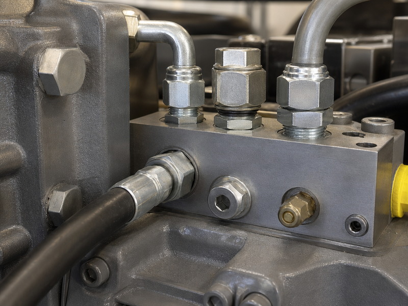
Figure 3. Real machines rarely carry a single standard: a JIC flare line, an ORFS high-impulse line, and metric DIN tube fittings can sit on the same machine. Identify each port individually before ordering.
Hydraulic Fitting Failures, Leaks, and Reuse Rules
Most hydraulic fitting failures are predictable and traceable to one of a small number of causes. Table 15 is the sequence HENGHUA technicians run when a leaking assembly comes back for inspection.
Table 15. Common hydraulic fitting failures, causes, and corrective action
| Symptom | Most likely cause | Corrective action |
|---|---|---|
| Weep at a JIC flare | Scored or deformed flare seat, or over-torqued nut | Replace the fitting; inspect both seats for damage before re-assembly |
| Leak at an ORFS face | Reused O-ring, pinched O-ring, or scratched sealing face | Fit a new O-ring; replace the fitting if the face is scored |
| NPT fitting weeps after weeks of service | Tapered joint relaxed under vibration or thermal cycling | Replace with an adapter to JIC, ORFS, or ORB and re-plumb the connection |
| Threads start, then bind | BSP and NPT, or metric and inch, mistaken for each other | Stop immediately; identify with a pitch and angle gauge; use the correct adapter |
| Leak at the hex of an ORB or ISO 6149 port | O-ring missing, pinched, or seated on a damaged chamfer | Fit a new port O-ring; check the chamfer and the port face |
| Continuous weep with no visible damage | Contamination on the sealing face or stretched threads | Clean or replace the fitting; flush the circuit if particles are present |
| Fitting pulls out of a hose end | Wrong ferrule for the hose construction, or an under-crimped assembly | Cut the hose back and re-crimp with the matching ferrule for that construction |
| Cracked port boss | Over-torque, or a tapered thread forced into a parallel port | Replace the component; specify the correct standard and an adapter next time |
Reuse Rules That Prevent Repeat Failures
Reuse rules differ across the hydraulic fitting types, and that difference decides what can go back onto a machine and what cannot. Table 16 sets out the details.
Table 16. Which fitting parts must be replaced at every re-make?
| Part | Reusable? | Basis |
|---|---|---|
| O-ring (ORFS, ORB, ISO 6149) | No — fit a new one | A compressed and heat-cycled O-ring has taken a set and will not seal reliably again |
| Bonded washer (BSPP) | No — fit a new one | The washer is the sealing element, not a fastener |
| Cutting ring (DIN 2353) | No, once seated | It bites into a tube at one final position; on a new tube it leaves the joint short of full engagement |
| Crimped hose end | No — cut off and replaced | Permanent by design, and not re-crimped |
| Reusable screw-together hose end | Yes, within its pressure limit | Built for field repair, with a lower rating than an equivalent crimp |
| JIC or ORFS metal body | Yes, if the seat and thread are undamaged | The metal parts can be re-made; the condition of the seat is the limit, and the seal elements are the parts that degrade |
Safety When Working on Hydraulic Fittings
Two rules are non-negotiable. First, relieve stored pressure and isolate the circuit before loosening anything; accumulators and raised implements hold pressure even with the pump off. Second, never use your hand to search for a high-pressure leak. A pinhole jet at 3,000 PSI can penetrate skin without pain at the moment of injury, and the resulting injection injury is a surgical emergency. Use a sheet of cardboard or paper to locate a suspected leak, and wear eye protection whenever a circuit is pressurised.
Foire aux questions
What does a hydraulic fitting identification chart look like?
A working fitting chart has one row per dash size and one column per family — JIC, ORFS, NPT, BSP and metric — so a single caliper reading can be read across every standard at once. Table 9 in this guide is that chart, and Table 10 is its reverse: a list of measured thread outside diameters with the standards each reading can indicate. Print both, or keep the PDF on a phone, because the chart narrows the candidates while a pitch or angle gauge finishes the identification.
What is the difference between JIC and ORFS fittings?
Both use a straight UNF thread, but not the same one: at -6, JIC is 9/16-18 and ORFS is 11/16-16, so ORFS threads are consistently one size larger for the same dash number. The seal is the real difference — JIC seals metal-to-metal on a 37° cone, while ORFS seals on an O-ring compressed between two flat faces. In the hand, a flat face with a captive O-ring is ORFS and a visible cone is JIC, and the two never seal against each other without an adapter.
How do I identify a hydraulic fitting when the marking is gone?
Measure the thread outside diameter with a caliper, check whether the thread is parallel or tapered, measure the pitch with a gauge, and then look for the seal feature — flare, flat face O-ring, O-ring under the hex, washer, or 24° cone. Thread diameter narrows the list; the seal feature finishes the identification. A caliper and a pitch gauge resolve nearly every case in under five minutes.
Is JIC the same as AN?
No. JIC and AN fittings share the same 37° seat angle and will often seal against each other, but AN uses a UNJ thread with a controlled root radius while JIC uses standard UNF threads. Specify by standard rather than by seat angle, and reserve AN-to-JIC assembly for emergency field repair rather than for a certificate-bound system. Our JIC fittings guide covers the seat, thread and torque details in depth.
What is the difference between ORB and ISO 6149?
ORB (SAE J1926) and ISO 6149 are the same idea in two thread systems: a straight thread with an O-ring under the hex that compresses into a chamfer in the port. The difference is the thread — inch UNF on the ORB side and metric on the ISO 6149 side — together with the port dimension that goes with it. Neither seals on a cone, so neither interchanges with DIN 2353, which seals on a 24° cone with a cutting ring even though it also uses metric threads.
Is BSP the same as NPT?
No, and this is the most damaging confusion in hydraulic fitting identification. BSP has a 55° thread angle; NPT has 60°. A 1/2-inch BSPT and a 1/2-inch NPT are both 14 threads per inch with diameters roughly 0.02 inch apart, so they start to thread together and then bind. Confirm with a pitch and angle gauge, and always join a BSP fitting to an NPT port with an adapter rather than by force.
Are stainless steel hydraulic fittings worth it on a mixed-standard machine?
On a machine that mixes JIC, ORFS and metric ports, stainless is usually justified by the environment rather than by the standard: washdown, marine, offshore and chemical exposure destroy zinc-plated steel long before the pressure rating becomes the limit. Where stainless is used, plan for galling on stainless-to-stainless joints with an anti-seize rated for the duty, and keep a caliper reading and a photograph of each port so the replacement can be matched without dismantling the machine.
What wrench size fits a JIC -6 fitting?
Hex size is set by the fitting manufacturer rather than by SAE J514, so it varies between producers and between a hose end, a bulkhead adapter and a stud end of the same thread. Measure the hex across the flats with a caliper and match that to your wrench set, or read the hex dimension from the catalogue entry for the exact part number. A wrench picked from the dash size alone will be one size wrong often enough to matter.
Which hydraulic fitting type leaks most often?
The failures we inspect most often are assembly problems rather than family problems, and two of them dominate: a joint built from two standards whose threads happened to match, and a seal element that was reused. On the family side, a tapered pipe thread in a high-impulse circuit is the weakest choice, because the threads are the only seal and they relax as the joint is cycled and vibrated.
Can I reuse a hydraulic fitting after removing it?
Metal parts can often be reused if the seats, faces and threads are undamaged; seal elements cannot. Replace every O-ring, washer and bonded seal, and treat a cutting ring that has already bitten into a tube as spent. A crimped hose end is permanent and must be cut off and replaced. Inspect any reused fitting for cracks and corrosion before it goes back into a pressure circuit.
How do I identify a fitting when the thread is damaged?
A damaged thread cannot be identified reliably from its diameter, so identify the joint from the half that is still intact: the port, the mating adapter, or the nut that came off it. Count the pitch on the least damaged crests with a gauge, note the seal feature — cone, flat face, O-ring under the hex, or washer face — and confirm against the port before ordering. Replace a fitting with crushed or deformed threads rather than measuring it; it will not reseal safely.
Can I use a JIC fitting in an ORFS port?
No, because the two seal in different places. A JIC male carries a 37° cone and needs a 37° female seat; an ORFS port or hose end presents a flat face with an O-ring. The cone has no flat face to compress the O-ring against, so the joint threads up, passes a visual check and leaks under pressure. Join the two families with a JIC male to ORFS adapter, and check the seal at both ends of it.
Final Verdict: Read the Port, Match the Standard, Verify the Supply
Sorting out hydraulic fitting types is a short, repeatable sequence. Identify whether the thread is parallel or tapered. Measure the diameter and the pitch. Look for the seal feature — a 37° flare, a flat O-ring face, an O-ring under the hex, a washer, or a 24° cone. Match the standard to the port, take torque from the manufacturer’s table, and join anything that differs with an adapter instead of force. Done in that order, the identification takes minutes and the joint stays dry.
HENGHUA manufactures hydraulic hose assemblies and supplies the fittings this guide covers — JIC, ORFS, NPT, BSP, SAE ORB, and metric DIN/ISO — in every dash size from -4 to -32, crimped onto wire-braid, spiral, and thermoplastic hose built to SAE J517 and EN standards.
Because our fittings and hose are produced and assembled in our own plant, we crimp and proof-test every assembly in house and can send the test report with the shipment rather than on request. We can also help where a machine mixes standards: send us the port measurements or photographs and our engineers will confirm which fitting, adapter, or complete assembly the machine actually needs.
Browse our hydraulic fittings range or request a quote and free samples. Send these five facts and we will confirm the correct standard before you commit to an order:
- The port standard at each end of the line.
- The fitting standard and the dash size you believe is correct.
- The working pressure, including surge if the circuit is shock-loaded.
- The quantity and the annual volume.
- The adapter requirement if the machine mixes standards.
We will tell you when a requirement falls outside what we manufacture rather than quote around it.
Written by the HENGHUA engineering team — the engineers who supply, crimp, and pressure-test the hose assemblies and fittings described in this guide, with input from equipment maintenance crews and OEM buyers in North America, Europe, and Asia-Pacific. The thread dimensions and sizes in this guide were checked against published SAE J514, SAE J1453, SAE J1926, ISO 8434-1, ISO 6149, ISO 228-1, ISO 7-1, and ASME B1.20.1 data; pressure and torque figures are typical values for steel fittings and the manufacturer’s data sheet for the exact part is the binding specification. HENGHUA is a hydraulic hose and fitting manufacturer with in-house production, crimping, and testing.
 English
  Spanish
  Portuguese
  French
  German
  Arabic
  Russian