
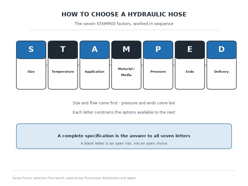
Knowing how to choose a hydraulic hose comes down to working through seven questions in a fixed order — Size, Temperature, Application, Material/Media, Pressure, Ends, and Delivery — the industry framework known as STAMPED. Answering all seven before you order prevents the most expensive mistake in hydraulics: a hose that satisfies one requirement while quietly failing another. For the most common line on mobile equipment, a -8 (1/2 inch) main pressure line, the answers resolve to SAE 100R2AT, 3,500 PSI working, -40 °C to +100 °C continuous, JIC 37-degree swivel ends, crimped and proof tested. This guide gives you the numbers behind each letter, the flow and pressure charts you check them against, the selection calculation behind the bore, and a worksheet you can send to a supplier — whether you are replacing one blown line on a loader or specifying a year of assemblies for an OEM program.
The Short Answer: How to Choose a Hydraulic Hose in Seven Checks
Choosing a hydraulic hose is a sequence, not a single decision. Size and flow come first because bore sets velocity; temperature and media decide the tube compound; application decides construction and bend radius; pressure sets the reinforcement family; ends decide whether the assembly will seal; delivery decides whether the parts arrive with the paperwork and lead time you need. Reorder the sequence and you will still reach an answer, but you will usually reach it twice — once on paper and once after the first failure. If you are new to hose specification, our hydraulic hose guide covers the construction, types, and ratings that sit behind these seven letters.
Table 1. The seven STAMPED letters: the question each one answers, what it decides, and the failure it prevents
| Letter | Question to answer | What it decides | Typical failure when skipped |
|---|---|---|---|
| S — Size | What is the bore, length, and flow? | Fluid velocity, pressure drop, heat | Overheated oil, pressure loss, kinked tight-radius lines |
| T — Temperature | What is the fluid and ambient temperature? | Tube and cover compound | Hard, cracked tube; early cover failure |
| A — Application | How does the line move, and what duty cycle? | Construction and bend radius | Braid fatigue, kink, abrasion wear |
| M — Material / Media | What fluid is inside? | Tube compatibility | Swelling, particle shedding, internal breakdown |
| P — Pressure | What is the working pressure and surge? | Reinforcement type and rating | Burst, wire fatigue at the crimp |
| E — Ends | Which threads and seals at both ports? | Fitting family and orientation | Leaks, blow-off, cross-threaded ports |
| D — Delivery | What documentation, packaging, and lead time? | Traceability and schedule | Unverified assemblies, downtime while you wait |
A complete hydraulic hose specification is the answer to all seven letters written down; a blank letter is an open risk, not an open choice.
What Is the STAMPED Method and Why Does Fluid Power Use It?
STAMPED is the acronym fluid power distributors, engineers, and maintenance planners use to describe the seven information areas required before a hose assembly is built or ordered: Size, Temperature, Application, Material/Media, Pressure, Ends, and Delivery. It is taught as an industry-wide practice rather than a manufacturer’s sales tool, which is why the same seven letters appear in training material from coupling makers, hose distributors, and repair workshops.
Used properly, STAMPED answers two questions at once: which hose the line needs, and how to choose a hydraulic hose that can be documented, reordered, and traced back to the production batch it came from.
The method survives because hydraulic hose fails for whichever requirement was ignored, not for the requirement you thought about most. A hose rated for 5,000 PSI but paired with a tube compound that swells in phosphate ester fails in weeks. A hose with the right compound, crimped with the wrong thread family, leaks on the first pressure cycle. STAMPED forces each requirement to be checked independently before the parts are cut.
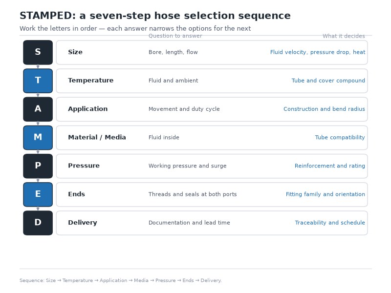
Figure 1. STAMPED is a sequence, not a checklist. Size and flow come first, pressure and ends last, because each letter constrains the options available to the next.
How STAMPED Differs From STAMP
STAMP stops at five letters: Size, Temperature, Application, Media, and Pressure. STAMPED adds Ends and Delivery — the two letters that decide whether the correctly rated hose becomes a working, documented, installable assembly. In practice, STAMP answers “which hose?” and the final two letters answer “which assembly, from whom, by when?”
For buyers, the last two letters carry more commercial weight than the first five. Two suppliers can quote the same SAE 100R2 hose at the same price per meter, and only one can produce a crimp record, impulse test data, and a batch number that ties the hose back to its compound lot. That difference shows up the first time a warranty question is asked.
Terminology in This Guide: R1, R2, and the AT Suffix
Where this guide writes R1 or R2 as shorthand, it means SAE 100R1 (single steel wire braid) and SAE 100R2 (double steel wire braid) — the American construction designations printed on a layline. They are unrelated to the R1 and R2 radius conventions (inner-surface radius and centreline radius) used to measure bends, and unrelated to the bend angles of end fittings. The AT suffix on a layline, as in SAE 100R2AT, is the thin-cover revision of the same construction; Type A and Type B are the superseded codes you may still find on older hose. EN 853 1SN and 2SN are the European equivalents of the same constructions — equivalent constructions, not identical published ratings, so always read the value for the standard family printed on the hose you are buying.
S — Size: What Bore Does This Flow Need?
Bore size is set by flow and velocity, not by the port thread. The most common sizing error in the field is copying a fitting size onto a hose: a 3/4-inch NPT port tells you the thread, not the bore the circuit needs. Size the hose from the flow the circuit must move and the velocity you are willing to accept, then confirm the ports can accept the matching ends.
Hydraulic hose selection starts with two numbers: the flow in gallons per minute and the bore that keeps velocity inside a workable band. Long pressure runs are commonly planned at 15–20 ft/s (4.6–6.1 m/s); short, straight pressure lines are often allowed up to roughly 26 ft/s; return lines run slower, at 10–15 ft/s (3.0–4.6 m/s); suction lines slower still, in the 3–5 ft/s range. Fast fluid means pressure drop, heat, and noise; a hose that is a size too large means extra weight, cost, and a stiffer line to route.
What Do Dash Sizes Mean in Inches and Millimetres?
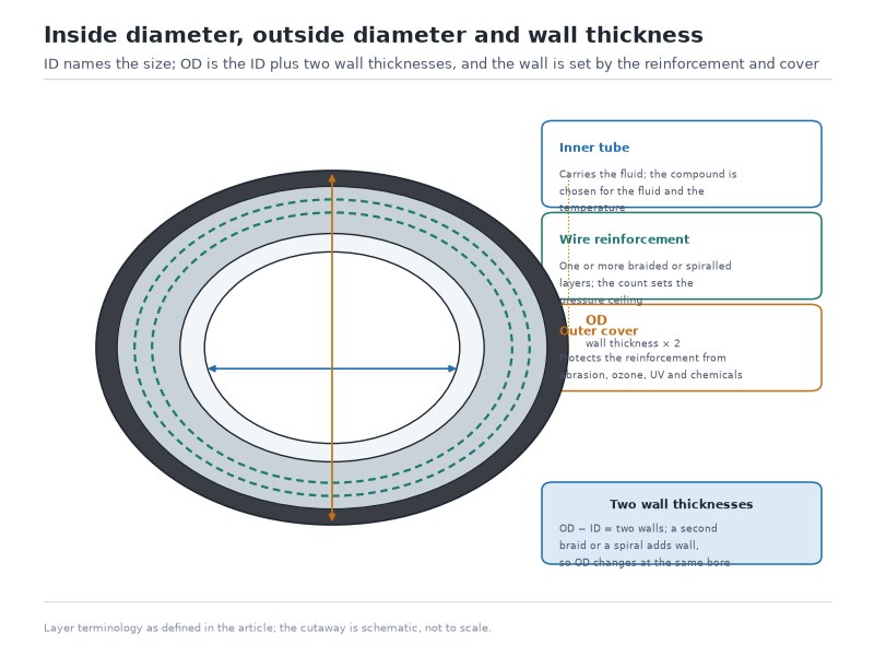
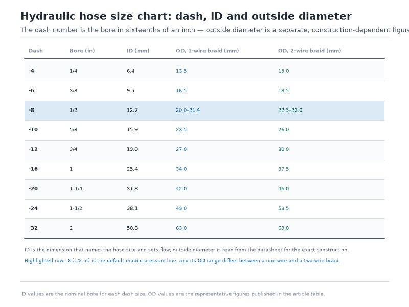
Hydraulic hose size is expressed in dash numbers, where one dash equals one-sixteenth of an inch of bore: -4 is 1/4 inch, -6 is 3/8 inch, -8 is 1/2 inch, -10 is 5/8 inch, and -16 is 1 inch. Size always refers to the inner diameter (ID). The outer diameter changes with the number of reinforcement layers, so two hoses of the same dash size — a 100R1 and a 100R6, for example — do not share the same OD.
Table 2. Hydraulic hose dash sizes, inner diameter, nominal flow capacity, and the flow each bore carries at exactly 20 ft/s (planning values; the practical band is the range commonly quoted for pressure-line service at that bore, spanning roughly 20–26 ft/s at the top of its flow range, while 15–20 ft/s is the figure used for long pressure runs; the 20 ft/s column is rounded to the nearest whole gpm, so a practical band opens at or within one gpm of the column value; the velocity examples quoted in this guide use the millimetre inner diameter printed in this table, which is why a hand calculation on the inch figure can differ by a tenth of a foot per second)
| Taille des tirets | ID (in) | ID (mm) | Flow at 20 ft/s (US gpm) | Practical band (US gpm) | Typical line |
|---|---|---|---|---|---|
| -4 | 1/4 | 6.4 | 3 | 3–5 | Pilot lines, gauge lines, small cylinders |
| -6 | 3/8 | 9.5 | 7 | 7–10 | Work-port lines on compact machines |
| -8 | 1/2 | 12.7 | 12 | 12–16 | Main pressure lines, tractor remotes |
| -10 | 5/8 | 15.9 | 19 | 19–25 | Working lines on mid-size machines |
| -12 | 3/4 | 19.0 | 28 | 28–35 | Large cylinder feeds, return lines |
| -16 | 1 | 25.4 | 49 | 49–60 | Heavy mobile equipment, presses |
| -20 | 1-1/4 | 31.8 | 76 | 75–95 | High-flow return and main lines |
| -24 | 1-1/2 | 38.1 | 110 | 110–130 | Heavy return and suction lines |
The hydraulic hose flow rate behind these numbers is estimated with one formula: Q (gpm) = V (ft/s) × A (in²) × 3.117, where A is the bore area, π/4 × ID². Read the constant as a unit conversion rather than a magic number: 3.117 = 2.448 × 4 ÷ π, so the same relationship written for velocity is v (ft/s) = Q (gpm) ÷ (π/4 × 3.117 × d² (in)). The 0.408, 2.448, and 3.117 constants used across hose literature are one relationship written for different unit systems, and they differ by under 0.2 percent. Check it against the table: a -6 hose has a 0.374-inch bore, so A = 0.110 in², and 7 gpm is the lowest flow that keeps velocity at 20 ft/s in that bore (7 ÷ (0.110 × 3.117) = 20.4 ft/s). That one formula is the whole hydraulic hose flow rate calculator — velocity times bore area times 3.117 — and the table above is the selection chart it produces.
The two flow columns answer two different questions. The practical band is the planning default for that bore in short pressure-line service, where velocity runs from about 20 to 26 ft/s. The velocity column is the arithmetic check, and it is the one that decides borderline cases: a flow below the band is not wrong, it simply means the line is running slower than the planning default, and a flow above the band pushes velocity toward the point where pressure drop and heat stop being negligible.
For a long pressure run, where pressure drop accumulates along the whole line, plan at 15–20 ft/s instead and size one dash up if the practical band would put the flow above that figure. When the two columns disagree on a borderline line, size on velocity, then confirm on the manufacturer’s flow table for the exact family you buy. Match the hydraulic hose flow rate to the line function as well, since return and suction lines run at lower velocity than pressure lines. The dash-to-ID-and-OD conversion behind these figures, with the tolerance band each size carries, is carried in full by our hydraulic hose size chart guide.
What Velocity Does Your Flow Run at in Each Dash Size?
Knowing how to choose a hydraulic hose for a given flow is mostly a velocity decision, and velocity is a table lookup followed by one division. Take the hydraulic hose flow rate your pump delivers, find the smallest dash size whose “Flow at 20 ft/s” figure is at or above it in Table 2, then confirm the result with v (ft/s) = Q (gpm) ÷ (π/4 × 3.117 × d² (in)). At 12 gpm the answer is -8, which runs at 19.6 ft/s and sits at the lower edge of that bore’s practical band. Drop to -6 and the same flow runs at 35.0 ft/s, well above the band, where pressure drop and heat — not the pressure rating — become the limiting problem. Step up to -10 or -12 and velocity falls to 12.5 or 8.8 ft/s, which adds weight, oil volume, and cost without buying anything back. The velocity answer, not the pressure answer, is what drives hydraulic hose selection between two neighbouring dash sizes.
How Do You Measure an Existing Hose Before Ordering a Replacement?
When a hose has no readable markings, measure it. Cut or find a clean cut end, measure the inside diameter across the bore with a caliper, and convert: every 1/16 inch of ID is one dash size. A 0.500-inch bore is a -8. Measure fittings separately — a fitting’s hex and thread size say nothing about the dash size of the hose it was crimped onto.
Where markings survive, the printed layline is faster: a line reading “SAE 100R2AT 3/8” gives you the standard family and the size in one glance. Our guide to reading a hydraulic hose layline explains every field printed on the cover, including the date code that tells you how old the hose already is.
Length and Allowance
Length is measured between the sealing faces of the two fittings, not the straight-line distance between ports. Add allowance for movement: a hose shortens slightly under pressure and lengthens as it is bent, so a line installed dead-taut pulls on the crimp every cycle. Give the line enough slack to follow its routing without ever straightening under load.
T — Temperature: Which of the Two Temperatures Sets the Rating?
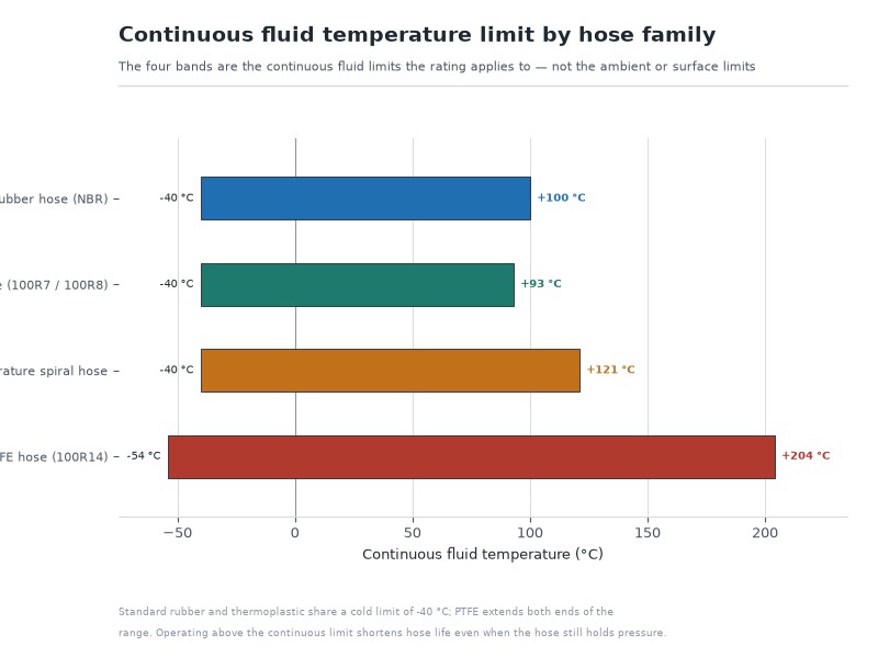
Temperature has two inputs — the fluid inside and the environment outside — and the hose must survive the higher of the two. Published limits fall into four construction families: standard nitrile-tube (NBR) rubber hose in the SAE 100R1, 100R2, 100R16, and 100R17 families is rated −40 °C to +100 °C continuous, with a short-term allowance of +120 °C; four- and six-spiral hose in the SAE 100R12 and 100R13 families is rated −40 °C to +121 °C; thermoplastic hose in the SAE 100R7 and 100R8 families is rated −40 °C to +93 °C; and PTFE hose in the SAE 100R14 family spans −54 °C to +204 °C, with high-temperature grades published to about +260 °C.
Table 3. Hydraulic hose temperature rating by construction family — continuous and short-term limits as published in SAE J517, ISO 3862 Type R12/R13, EN 856 4SP/4SH, EN 853 1SN/2SN, EN 857 2SC, EN 855 R7/R8 and ISO 3949 (confirm the exact family and size on the manufacturer’s data sheet)
| Construction family | Continuous | Short-term / intermittent | Best suited to |
|---|---|---|---|
| Standard rubber, NBR tube — SAE 100R1, 100R2, 100R16, 100R17 (EN 853 1SN/2SN, EN 857 2SC) | −40 °C to +100 °C | +120 °C for about 10 percent of running time | Mineral-oil systems on mobile and industrial machines |
| Four- and six-spiral — SAE 100R12, 100R13, 100R15 (ISO 3862 Type R12/R13, EN 856 4SP/4SH) | −40 °C to +121 °C | Take the intermittent value from the manufacturer’s data sheet | High-impulse pressure circuits, mining and offshore duty |
| Thermoplastic — SAE 100R7, 100R8 (EN 855 R7/R8, ISO 3949) | −40 °C to +93 °C | Narrower band than rubber — check the data sheet | Tools, utility equipment, tight routing, chemical exposure |
| PTFE — SAE 100R14 with stainless braid | −54 °C to +204 °C | High-temperature grades published to about +260 °C | Extreme heat, aggressive fluids, steam |
The limits above are family values, not marketing claims: the spiral figures come from ISO 3862 Type R12/R13 and EN 856, the standard-rubber figures from EN 853 and EN 857, and the thermoplastic figures from EN 855 and ISO 3949, all carried into SAE J517 for the 100R series. Families this guide does not list per size — textile braid, the compact grades, and specialty constructions — are charted family by family in our hydraulic hose temperature rating chart, which is the page to open when a line runs close to a limit.
Why Does the Pressure Rating Fall as Temperature Rises?
A high fluid temperature does more than stress the tube: heat softens the rubber compounds that hold the reinforcement in place, so every hose has a temperature above which the published working pressure no longer applies. That point is defined in the data sheet, and above it the rating is derated step by step. Selecting a hose by its printed pressure rating while ignoring a fluid temperature of 110 °C is one of the few ways to buy a correctly rated hose that still fails early — and it is the reason the temperature letter comes before the pressure letter.
Ambient Heat Is the Input People Forget
Radiant heat from an exhaust manifold, turbo, or engine block raises the cover temperature far above the oil temperature, and a standard cover degrades where it is hottest. When a line runs within a few centimetres of a constant heat source, the fix is a heat-resistant cover or a protective sleeve — not a bigger pressure rating. Working on engine-adjacent lines for OEM customers, we have found sleeve coverage at the hot spot extends cover life further than any change of hose family at the same bore, so the sleeve is the first thing to specify and the last thing to cut. A hydraulic hose temperature rating quoted for the fluid does not cover that surface case, which is why the two temperatures have to be checked separately.
A — Application: How Often Does This Line Move, and How Tight Does It Bend?
Application is the letter that decides construction, because it describes how the line will actually live: how often it flexes, how tight it bends, what it rubs against, and how hard the circuit works it. Two circuits at identical pressure and size can need different hoses purely because one flexes ten times a day and the other flexes ten times a minute.
Minimum Bend Radius: The Limit That Kinks Hoses
Every hose has a published minimum hydraulic hose bend radius — the tightest curve it can hold without collapsing the reinforcement or cracking the tube. For steel-reinforced braided hose the same values are used across this site: the published figure lands between 12 and 16 times the nominal bore for single-wire-braid hose, and between 13 and 19 times the bore for four-spiral hose; compact families (SAE 100R16, 100R17) are designed specifically to reduce that figure. As reference points for the sizes people ask about most, a 3/8-inch SAE 100R2 hose carries a minimum bend radius of about 5.1 inches (130 mm), and a 1/2-inch hose between 6 and 8 inches (152–203 mm) depending on construction; the full set of 3/8 hydraulic hose bend radius and 1/2 hydraulic hose bend radius values by family is published in each data sheet.
Table 4. Hydraulic hose bend radius guidance by construction family (typical values; the multiples are the published bend radius values for steel-reinforced families, textile and thermoplastic rows are compared by family because their minimum is quoted per size — confirm each size in the data sheet)
| Family | Renfort | Typical minimum bend radius | Flex behaviour in service |
|---|---|---|---|
| SAE 100R6, 100R3 | Textile braid | Tightest of the low-pressure families | Very flexible; return, drain, and pilot duty |
| SAE 100R7 / 100R8 | Thermoplastic, fibre or aramid | Compact, comparable to 100R2 at smaller OD | Light, kink-resistant, chemically robust |
| SAE 100R1 | Single wire braid | 12–16 × nominal bore (about 5.1 in / 130 mm at -6) | General low- to medium-pressure lines |
| SAE 100R2 | Double wire braid | 12–16 × nominal bore (about 5.1 in / 130 mm at -6; 6–8 in / 152–203 mm at -8) | The mobile-equipment workhorse |
| SAE 100R12 / 100R13 / 100R15 | Four- to six-spiral wire | 13–19 × nominal bore (widest of the rubber families) | High impulse, minimal elongation, stiff to route |
Routing discipline matters as much as the number. Let the hose leave the ferrule straight for a short distance before the first bend begins, because a bend that starts at the crimp concentrates stress exactly where the assembly is least able to absorb it. Where a tight turn is unavoidable, use an elbow fitting or an adapter instead of forcing the hose.
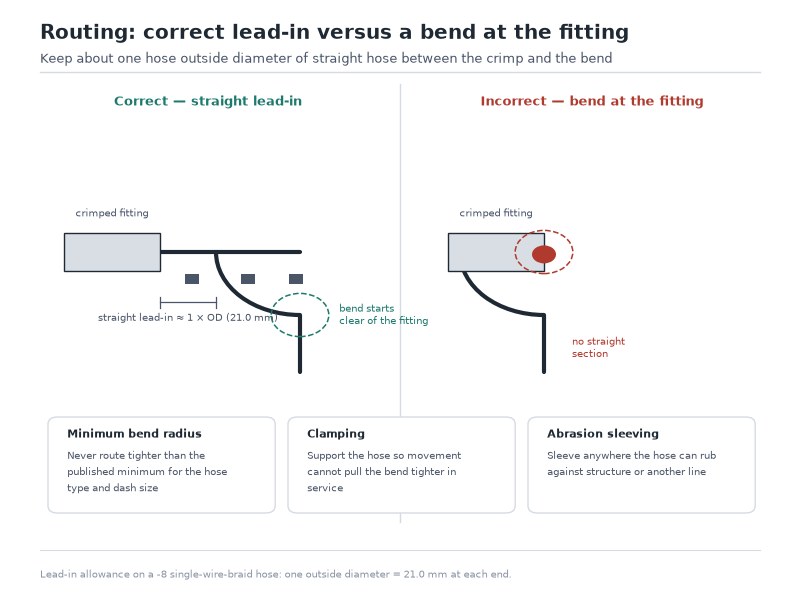
Figure 2. The four routing rules that decide service life: respect the hydraulic hose bend radius, leave the ferrule straight before the first bend, clamp anything that moves, and sleeve anything that contacts metal or heat.
Duty Cycle and Impulse Decide the Reinforcement
Impulse — the repeated pressure spike of a working circuit — is what fatigues wire reinforcement. The reference test is defined by SAE J343 and its international equivalent EN ISO 6803: pressure cycles at 133 percent of rated working pressure, at a fluid temperature of +100 °C, at a cycling rate of 0.5–1.25 Hz, for a minimum of 200,000 cycles in the published requirement. Buying programs for high-impulse circuits commonly call for longer runs — 500,000 or 1,000,000 cycles — as a commercial qualification level on top of that minimum, so treat the cycle count in a quote as a program requirement rather than a fixed standard figure, and ask which standard it was tested to. A circuit that cycles a few times a day can live happily on a single-wire braid; a boom that stalls under load dozens of times an hour cannot.
Abrasion, Environment, and Hose in Motion
Abrasion destroys more hydraulic hose in the field than pressure does. Every uncovered contact point — a frame rail, a clamp edge, another hose — removes cover material until the wire reinforcement is exposed, and exposed wire corrodes and then fatigues. Three countermeasures cover most cases: route the line so it does not touch structure, clamp it where it must, and add an abrasion sleeve at every unavoidable contact point. Where two hoses must cross, crossing at 90 degrees wears far more slowly than running parallel in contact.
M — Material / Media: Which Tube Compound Does This Fluid Need?
The inner tube must be chemically compatible with the fluid, and compatibility is not a preference — it is a hard requirement. Standard hydraulic hose uses a nitrile (NBR) tube, which handles mineral hydraulic oil, the fluid in the overwhelming majority of machines, extremely well. Change the fluid and the tube compound often has to change with it.
Table 5. Fluid compatibility by tube compound for hydraulic hose (confirm against the hose manufacturer’s compatibility list before ordering)
| Fluid | Designation | NBR (standard) tube | What to specify instead |
|---|---|---|---|
| Mineral hydraulic oil | HL, HLP, ISO VG 32–68 | Suitable — the default | Nothing further; NBR is the correct tube |
| Water-glycol | HFC | Not rated for this fluid | A hose certified for HFC fluids |
| Water-oil emulsion | HFB | Not rated for this fluid | A hose certified for HFB fluids |
| Biodegradable ester | HEES, HETG | Limited compatibility | Synthetic-rubber or thermoplastic tube rated for esters |
| Phosphate ester | HFD-R | Swells and sheds particles — do not use | EPDM or butyl tube, or PTFE |
| Water, air, mild chemicals | — | Reserved for oil service | Thermoplastic or PTFE hose for pressure duty |
Why a Compatible-Looking Hose Can Still Be Wrong
Fire-resistant fluids are the classic trap. A machine converted from mineral oil to phosphate ester keeps the same pressure, temperature, and size requirements — and destroys a standard NBR-tubed hose from the inside. The symptoms are not dramatic at first: the tube swells, sheds particles into the oil, and quietly contaminates the system before the hose fails. By the time a filter or a valve shows the damage, the cost is no longer the price of a hose.
Substituting across duty types carries the same risk in reverse. A fuel hose, an air hose, and a hydraulic hose can look similar from the outside, but only the hydraulic hose carries steel or textile reinforcement rated for pressure. Installing anything else in a hydraulic circuit trades a small saving for an unpredictable burst — our hydraulic hose vs air hose comparison sets out how far apart the two ratings really are. If the fluid is not mineral oil, say so in the specification — this is the detail that separates a routine quote from a correct one. Our guide to selecting the right hydraulic oil hose covers the fluid side of the decision in more depth, and hydraulic hose selection for mobile equipment usually starts from that mineral-oil default.
P — Pressure: What Working Pressure and Surge Allowance Do You Specify?
Two pressure numbers are printed on a hydraulic hose, and only one of them belongs in your specification. Working pressure is the maximum pressure the hose may carry in continuous service. Burst pressure is the destruction value from testing: under SAE J517, EN 853, and EN 857 the standard specifies a minimum burst pressure of four times the maximum working pressure, and that four-times figure is a qualification requirement, not a target to operate at. Every hydraulic hose pressure rating printed on a layline or quoted in a catalogue is a working pressure unless the table explicitly says otherwise. Surge is the number in between: the momentary spike when a valve shifts or a load changes. Industry practice is to allow for surge by applying a surge factor on top of the maximum system pressure rather than by reading a fixed figure from a standard — that factor is a design convention, not a published rating method.
Table 6. Typical hydraulic hose pressure rating by family and size for the bores the STAMPED sequence most often settles on (published values per SAE J517 for the 100R1AT and 100R2AT families; the EN 853 1SN and 2SN equivalents publish a different set of values for the same dash size, so confirm the exact rating for the family and bore you order)
| Bore | SAE J517 100R1AT working (PSI) | SAE J517 100R2AT working (PSI) | Reinforcement it tells you to consider |
|---|---|---|---|
| -4 (1/4 in) | 3,000 | 5,000 | Two-wire braid covers most duty at this bore |
| -6 (3/8 in) | 2,250 | 4,000 | Two-wire braid unless the circuit is high-impulse |
| -8 (1/2 in) | 2,000 | 3,500 | Two-wire braid for general mobile duty |
| -16 (1 in) | 1,000 | 2,000 | Spiral when both flow and pressure must rise |
Working pressure falls as bore rises: SAE 100R2 is rated 4,000 PSI in -6 (3/8 in) and 2,000 PSI in -16 (1 in), the same construction at four times the flow area. Both columns are SAE J517 values — 100R1AT for the single-braid column and 100R2AT for the double-braid column — and the European equivalents publish a different set for the same dash size: EN 853 2SN publishes 2,250 PSI in -16 where SAE 100R2AT shows 2,000 PSI. Those are two different standard bases, not a contradiction, which is why the family printed on the layline is the figure that governs.
That trade-off is why the size letter comes before the pressure letter in STAMPED — you need the final bore before you can read the correct rating. Read the full hydraulic hose pressure rating guide before you fix the bore, and use this table only to see the direction the numbers move.
When Do You Need Spiral Instead of Two-Wire Braid?
Above roughly 3,000 PSI, wire-braid or spiral construction becomes the standard rather than the upgrade. Four- and six-spiral families (SAE 100R12, 100R13, 100R15, and DIN EN 856 4SP/4SH) reach the 4,000–6,000 PSI band and resist impulse better because alternating wire layers limit how much the hose expands under pressure. Below that band, spiral reinforcement buys nothing except weight, stiffness, and cost per meter.
How Do You Size for Surge Rather Than the Gauge Reading?
The gauge tells you steady-state pressure; the hose sees the spike. On circuits that shift under load — excavator booms, log splitters, compaction rams, presses — apply a surge factor of 1.25 to the maximum system pressure before you read the rating table (the design convention noted above, not a published standard requirement); a machine with unusually hard shifting can justify a larger one. A 2,500 PSI circuit with a 25 percent surge allowance needs a hose rated 3,125 PSI or higher, which in -8 bore means 100R2 rather than 100R1. For systems where the duty is genuinely high-impulse, the comparison between 2-wire braid and 4-wire spiral hose explains where the crossover sits, and why impulse life rather than burst pressure is the deciding figure.
What Derates a Hydraulic Hose Pressure Rating
Three conditions reduce the usable pressure rating below the printed figure: temperature at the top of the range, sustained vacuum in suction duty, and repeated bending tighter than the published bend radius. Each is handled in the data sheet with its own derating table or installation limit, and each is a reason to specify above the bare minimum rather than exactly at it. Never trace a leak on a pressurized hose with your hand: hydraulic fluid under pressure can penetrate skin, and fluid-injection injuries are treated as surgical emergencies — use a piece of cardboard or a leak-detection dye instead.
E — Ends: Which Thread Family and Seal Does Each Port Need?
Ends turn a hose into an assembly, and thread families are not interchangeable. The most expensive end-fitting error is a connection that threads together and still cannot seal, because the two halves use different sealing geometry. JIC (Joint Industry Council) seals on a 37-degree metal cone, ORFS (O-ring face seal) seals on an O-ring at a flat face, NPT (National Pipe Taper) seals on the tapered threads themselves, and BSP (British Standard Pipe) comes in both parallel and tapered forms that look like NPT and are not. Ends are also the letter most often left out when someone asks how to choose a hydraulic hose in a hurry, and it is the one that produces the fastest leak.
Table 7. Common hydraulic hose end fitting families, how each one seals, and where each is found (see our hydraulic fittings types guide for the full range)
| End style | Thread | Sealing method | Typical region or equipment |
|---|---|---|---|
| JIC 37° flare | UNF | Metal-to-metal cone and seat | General industrial and mobile equipment worldwide |
| ORFS | UNF | O-ring at a flat face | High-pressure circuits where vibration is constant |
| NPT / NPTF | Tapered pipe thread | The tapered thread itself, with sealant | North American ports and older equipment |
| BSPP / BSPT | British parallel or tapered | Bonded washer or taper | European and Asian machinery |
| SAE code 61 / 62 flange | Four-bolt split flange | O-ring under the flange head | Large bores, high flow, high pressure |
| Metric 24° cone (DIN) | Metric | Metal-to-metal cone with a cutting ring or soft seal | European mobile and industrial systems |
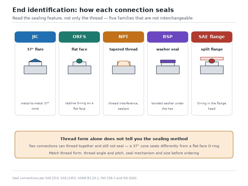
Figure 3. Four sealing principles cover almost every hydraulic end: a 37-degree metal cone, an O-ring at a flat face, a tapered thread, and a flange sealing on an O-ring underneath.
Before you commit to a set of ends, confirm five things on the machine:
- The thread form and size of both ports, measured or matched against a known fitting rather than guessed.
- The sealing method each port expects, so that a cone-seat fitting is only threaded into a port that accepts a cone.
- The pressure and temperature capability of the fitting family, which must match or exceed the hose it is crimped onto.
- The angle between fittings and the direction each elbow must point once the assembly is installed.
- Whether the end must swivel after tightening, since an assembly without a swivel joint cannot be clocked in the field — add a swivel joint wherever the routing has to be timed after the fitting is tight.
Crimped or Reusable Ends
Crimped fittings are pressed onto the hose with a calibrated machine and cannot be re-crimped once removed — the ferrule has already taken its permanent deformation. That is not a drawback; it is the reason a factory crimp is repeatable and verifiable. Reusable fittings screw on in the field and suit emergency repair on larger sizes, but they carry a lower performance ceiling and demand correct assembly every time.
How Do You Get the Ends Clocked and the Assembly Clean?
An assembly has an angle: elbows must point in the direction the routing requires, and a 45-degree or 90-degree right angle elbow clocked in the wrong position turns an easy installation into a forced one. Specify the angle between fittings when you order, especially for lines that route around a cylinder or under a cab. Cap and plug every finished assembly before it leaves the bench or the factory. A hose stored open-ended in a workshop collects grit, and grit is what turns a correctly specified assembly into a pump or valve failure six months later. If you need finished, tested hydraulic hose assemblies with the ends clocked to your drawing, our hydraulic hose assembly range covers crimped metric, BSP, JIC, NPT, and ORFS configurations.
D — Delivery: What Documentation, Packing, and Lead Time Do You Need?
The last letter is where a hose becomes a hose assembly you can actually install, and it is the step most people skip when they learn how to choose a hydraulic hose. Delivery also decides which supplier the order goes to: what proof and test documentation comes with the assembly, how the finished hose is packed and protected, how long the lead time really is, and how the supplier handles a defect — four practical questions that a price per meter never answers.
Table 8. Delivery checklist — documentation and commercial terms to request with every hydraulic hose order
| Article | Why it matters | What to ask for |
|---|---|---|
| Proof test record | Confirms the finished assembly held pressure before shipment | Test pressure used, quantity tested, per-batch result |
| Crimp record | Ties the assembly to the correct die and crimp diameter | Crimp diameter and machine setting per fitting part number |
| Batch traceability | Links a failure back to compound and reinforcement lots | Batch or lot number on the assembly and on the paperwork |
| Layline marking | Lets anyone on site re-order the same hose without guesswork | Standard family, size, pressure rating, and date code printed on the cover |
| Packing and caps | Prevents contamination and kinking in transit and storage | Capped ends, coil or reel diameter stated, no sharp bends in the box |
| Lead time and MOQ | Decides whether you can plan a shutdown around the order | Committed lead time by size, sample quantity, and re-order interval |
| Warranty terms | Settles the argument before it happens | Written warranty period and the conditions that void it |
A proof test record and a batch number change the risk of a hydraulic hose order more than the price per meter does: the proof record covers the crimped joint, which is the first thing to fail on a new assembly, and the batch number is what makes a warranty claim possible six months later, because it lets the manufacturer trace the compound and the crimp setting used on that production run.
What Drives the Cost of a Hydraulic Hose Order
Price per meter is only one line in a hose budget, and it is rarely the largest. Four factors move the total more than the hose itself: the construction family, since four- and six-spiral hose costs a multiple of two-wire braid in the same bore; the number and style of fittings on each assembly; the testing and documentation you ask for, because proof testing and crimp records consume process time; and order volume, since bulk quantities spread setup and freight while a single replacement length carries the full setup cost. Cover compound, temperature grade, and abrasion sleeving all add cost, and all three are the cheapest insurance in the order.
When you compare quotes, compare the delivered cost per assembly — hose, fittings, crimping, testing, packing, and lead time together. A lower price per meter paired with a four-week lead time is not the lower-cost option if the machine is standing still, and MOQ terms that force you to hold a year of stock are a cost as well. Ask for the quote broken down by line item so the comparison is honest, and ask what changes if the volume doubles. If the comparison is between a quote you already have and one you are waiting for, send us the line item breakdown, the annual volume, and the shutdown window — the same nine-item list used in the inquiry checklist later in this guide, weighted to the commercial side — and our engineers will return a delivered cost per assembly with the test records included.
What Does a Completed STAMPED Specification Look Like?
This is how to choose a hydraulic hose for a tractor loader boom-lift line at 2,500 PSI and 12 gpm: it specifies as SAE 100R2AT, dash -8, 1,850 mm, JIC swivel straight × 90-degree elbow, NBR tube, crimped and proof tested — one order line with no open letters. Table 9 works that same line letter by letter; if you have only one of the seven answers today, Table 10 tells you which letter to work first.
Table 9. Filled STAMPED worksheet for a tractor loader boom-lift pressure line
| Letter | Requirement gathered from the machine | Decision it produces |
|---|---|---|
| S — Size | Pump flow 12 gpm; existing bore measures 0.50 in; length 1,850 mm between sealing faces | -8 dash, 1/2 in bore: 12 gpm in that bore runs at 19.6 ft/s, the lower edge of that bore’s practical band and inside the 15–20 ft/s figure used for long pressure runs; -8 is the smallest bore that carries the flow at that velocity |
| T — Temperature | Oil reaches about 80 °C in summer work; line passes near the engine bay | Standard NBR tube and cover, rated −40 °C to +100 °C continuous with a +120 °C short-term allowance; abrasion sleeve at the hot contact point |
| A — Application | Lift and lower every working cycle; hose flexes in service; published minimum bend radius 6 to 8 in (152–203 mm) for this size | Two-wire braid construction; route with at least a 6 in (152 mm) bend and slack for cylinder movement |
| M — Material / Media | Mineral hydraulic oil, ISO VG 46, no fire-resistant fluid in the system | NBR tube — no special compound needed |
| P — Pressure | System relief 2,500 PSI; shock loads during lifting; a 1.25 surge factor applied gives 3,125 PSI | SAE 100R2, rated 3,500 PSI working in -8, with the minimum burst pressure specified at four times the working pressure per SAE J517 and EN 853 |
| E — Ends | JIC 37° ports at valve and cylinder; elbow needed at the cylinder to clear the arm | 1/2 in JIC male swivel both ends, 90° elbow clocked to the routing drawing |
| D — Delivery | Planned shutdown in three weeks; fleet keeps two spare lines per machine | Factory-crimped assemblies with proof test record, capped ends, delivered in bulk |
The result is one order line: SAE 100R2AT, dash -8, 1,850 mm, JIC male swivel straight × JIC male swivel 90-degree elbow, standard NBR tube, crimped and proof tested, capped, batch traceable. Nothing in that specification is guesswork, and any of the seven letters could have changed the answer on its own.
The bore had to be fixed before the pressure could be read: 3,500 PSI is the -8 rating for this family, not the 5,000 PSI the same construction carries in -4. And if that same line ran on a 20-ton excavator boom at 3,500 PSI with 45 gpm of flow, the size would move to -16 and the reinforcement to four-spiral — the excavator hydraulic hose guide shows how quickly a mobile machine’s duty cycle pushes the specification upward. Bore, flow, and impulse all rise together on heavy equipment; each one independently rules out the lighter construction.
Where Should You Start If You Only Have One Answer?
Table 10. Where to start, depending on what you already know (a routing table, not a specification: it chooses which STAMPED letter to work first)
| Your situation | Letters to work first | First action |
|---|---|---|
| One line failed and the machine is down | S, then E | Read the layline on the failed hose; measure the bore on a cut end and the length between sealing faces |
| The same line fails every season | A, then M | Photograph the failure point and read the date code: a kinked section points to routing, a swollen tube points to the fluid, and a crack at the ferrule points to the crimp or the installation |
| Specifying a year of assemblies for an OEM program | All seven, in order | Fill the worksheet above for the highest-duty line first, then repeat it line by line |
| Quoting a stock list for a distributor | S, then P | Compare the -6, -8, and -12 ratings across the constructions you stock before you quote a lead time |
| Comparing supplier quotes | D, then the cost section | Ask for the delivered cost per assembly, the proof test record, and which pressure figure each quote is using |
What Are the Five Most Common Hose Selection Mistakes?
Most field failures trace back to one of five shortcuts taken while deciding how to choose a hydraulic hose. None of them is exotic, and all five are avoidable at the specification stage.
- Sizing from the fitting thread. A 3/4-inch port says nothing about the bore the circuit needs. Measure the old hose’s ID or read the layline.
- Selecting by burst pressure. Burst is a destruction-test figure: SAE J517, EN 853, and EN 857 specify a minimum burst pressure of four times the working pressure. Design and operate against the working rating, allowing for surge.
- Ignoring surge and duty cycle. Steady-state pressure on a gauge is not what fatigues wire braid. High-impulse circuits need either a heavier braid or spiral reinforcement, and a cycle count quoted in a purchasing program.
- Downgrading the standard when a part is unavailable. Replacing a 100R2 line with 100R1 because the pressure numbers look close discards impulse and temperature performance that the original rating carried.
- Treating ends and documentation as an afterthought. Reusing a crimped ferrule, mismatching a thread family, or accepting an assembly with no test record moves the risk from the supplier to your maintenance budget.
If a hose has already failed, the failure pattern usually names the letter that was missed. Abrasion through the cover points to routing and sleeve coverage; a kinked section points to bend radius; a swollen tube points to media; a crack at the ferrule points to installation or crimp. Our breakdown of the ten most common hydraulic hose failure causes maps each visible symptom back to its cause.
Foire aux questions
What is the STAMPED method for hydraulic hose selection?
STAMPED is the seven-factor framework used across fluid power: Size, Temperature, Application, Material/Media, Pressure, Ends, and Delivery. Each letter is a separate requirement that the finished assembly must satisfy, and the letters are worked in that order so that size and flow decisions are made before pressure and end fittings are chosen.
What size hydraulic hose do I need for 20 gpm?
Rather than reading one cell of Table 2, work the flow through velocity. In Table 2, 20 gpm sits in the -10 (5/8-inch) band of 19–25 gpm; in that bore the velocity works out at about 20.8 ft/s, which is inside the 20–26 ft/s planning band used for a short pressure line at that bore but just above the 15–20 ft/s figure used for a long pressure run — exactly the borderline case the velocity column exists to expose.
A -8 bore would push the same flow to about 32.7 ft/s, well above the band, and that excess velocity shows up as pressure drop and heat. A -12 bore is safe but oversized: the same 20 gpm would run at only 14.6 ft/s, which costs weight, oil volume, and money for no benefit. The trade-off between the two columns of the table is deliberate: the practical band is the planning default for a short pressure line, and the velocity check decides borderline cases such as this one.
How do I use working pressure and burst pressure when I specify a hose?
Specify on working pressure with a surge allowance on top, and treat the burst figure as the standard’s minimum requirement rather than a design target. In selection, what matters is that the rating you read from a table, a layline, or a quote is always the working figure; working, proof, and burst pressure are defined separately and are covered in our guide to hydraulic hose pressure rating. A practical test of any quote: if the seller cannot say which of the three numbers you are being given, the number is not usable.
How do I choose a hydraulic hose if I only know the flow rate?
You can narrow the field to two candidates. Flow plus a velocity band gives the bore from the flow table, and the bore then rules out every family whose published rating is too low at that size. What flow alone cannot answer is the reinforcement, because impulse duty, fluid temperature, and surge decide that; so quote the bore and say “flow only, duty unknown” — a supplier should reply with the two constructions that fit and the questions still open, not a single offer.
Do I need a spiral hose, or is two-wire braid enough?
Two-wire braid (SAE 100R2) covers most mobile and industrial circuits up to roughly 4,000 PSI in small bore. Move to four- or six-spiral construction when the system runs above about 4,000 PSI, when surge events happen constantly, or when the hose must hold pressure without elongating — boom cylinders, rock drills, presses, and offshore equipment. A quick field test: if the line is on a machine that stalls under load many times an hour, price the spiral version and compare it against the replacement interval you are actually achieving on braid.
Which temperature do I rate the hose against?
Rate against the higher of fluid temperature and ambient or surface temperature, then check whether the working pressure you selected still holds at that temperature. Standard NBR rubber hose is published to +100 °C continuous with a +120 °C short-term allowance, spiral hose to +121 °C, thermoplastic to +93 °C, and PTFE to +204 °C. Surface temperature is the input that gets missed: a line running 30 mm from an exhaust manifold sees a cover temperature far above the oil temperature, which is a cover and sleeve problem, not a fluid problem.
Do I need a different hose for a return line than for a pressure line?
Yes — a return line needs a different hose from a pressure line, and the difference is set by velocity rather than by pressure. Return lines run at 10–15 ft/s and typically carry only a fraction of the system pressure, so a lighter construction — textile braid, compact braid, or a smaller wire-braid family — is usually correct, with more flexibility for the run back to the tank. Two limits apply: the return line still has to survive peak pressure from a blocked filter or a closed valve, and a suction line has to resist vacuum, which is a different requirement again.
How do I tell which end-fitting family a port needs?
Identify the sealing geometry before the thread. A 37-degree cone inside the port means a JIC-style flare; a flat face with a recessed O-ring means an ORFS-style seal; a port whose threads do the sealing is tapered pipe thread (NPT or BSPT); a parallel port with a machined face expects a bonded washer or an O-ring. Measure the thread outside diameter and count the threads per inch to pin the size, and match it against a known fitting rather than a photograph — two families can share a thread diameter and still refuse to seal against each other.
How long does a hydraulic hose last?
Under normal pressure, temperature, and environmental conditions, five to ten years from the date code is a reasonable working expectation. High-cycle machines such as excavator boom lines are often replaced every two to three years, and heat, surge, abrasion, and UV shorten life further — so re-check the hydraulic hose temperature rating before extending any replacement interval. Inspect at every service interval rather than waiting for a calendar date: the date code tells you the age of the rubber, not the duty it has seen.
Why does the hose size chart show lower pressure ratings for bigger hoses?
Because the same reinforcing load is carried over a larger circumference, a bigger bore has to be rated at a lower working pressure. A 3/8-inch SAE 100R2 hose is rated 4,000 PSI while the 1-inch version of the same construction is rated 2,000 PSI. When a circuit needs both higher flow and higher pressure, the answer is usually a spiral construction rather than a larger hose — which is exactly the trade-off the pressure letter is meant to surface before the order is placed.
How do I write a hydraulic hose line into a drawing or a BOM?
Write the seven answers in a fixed field order so any supplier can read it without asking questions: standard family and type, dash size and bore, assembly length between sealing faces, working pressure with the minimum burst pressure referenced to the standard, tube compound and temperature range, end fittings with thread family and elbow angles, and quantity with the documentation required. Adding the reference standard to the pressure field — for example “3,500 PSI working, minimum burst four times working pressure per SAE J517” — removes the ambiguity that causes a quote to be revised later.
What should I include in a hydraulic hose inquiry?
Send nine items: flow or existing bore and length; fluid and temperature range; application and duty cycle with any routing or impulse constraints; standard family if known (for example SAE 100R2); working pressure plus surge; end fitting thread families and any elbow angles; annual volume; target delivery window and documentation needs; and a photograph of the failed line with the point where it failed marked. Working those answers through the STAMPED order is the practical answer to how to choose a hydraulic hose under time pressure.
What is the fastest way to choose a hydraulic hose for a replacement line?
For a replacement line, the fastest route is to copy the failed hose, starting from the layline. Read the standard family, size, and pressure rating off the cover; measure the bore across a cut end if the markings are gone; measure the assembly length between sealing faces; note both end fitting families and the angle between them; and photograph the failure point so the supplier can see whether the original hose was under-specified. Order the same specification unless the failure pattern shows the original rating was the problem — in which case change the one letter the failure points to, not the whole specification.
Final Verdict: Work STAMPED in Order, Then Verify the Manufacturer
Knowing how to choose a hydraulic hose comes down to discipline rather than product knowledge: work the seven letters in order, write the answers down, and refuse to order until every letter has a value. Size and flow first, temperature and media next, application and pressure after that, then ends and finally delivery. A line specified that way is usually right the first time, and it is documented well enough that the next person who orders it gets the same result.
The last step is the manufacturer. Consistent hose performance comes from controlling the whole process — compound mixing, wire braiding, extrusion, crimping, and pressure testing — because variation in any of those steps changes the assembly’s impulse life even when the layline reads the same. HENGHUA manufactures hydraulic hose and crimped assemblies to SAE J517, DIN EN 853, and EN 856 in bores from 6 mm to 51 mm, with working pressures up to 45 MPa (6,500 PSI), 100 percent proof testing on finished assemblies, batch traceability, and crimping in metric, JIC, ORFS, NPT, and BSP configurations. If you have a specification, send it and we will confirm the construction, quote, and lead time.
If you are still deciding, send the seven STAMPED answers — the nine-item inquiry list in the FAQ above adds the annual volume, the delivery window, and a photograph of the failed line — and our engineers will complete the specification with you. Whether you are buying one replacement line or a year of assemblies, that is how to choose a hydraulic hose without guesswork. Request a quote and free samples.
 English
  Spanish
  Portuguese
  French
  German
  Arabic
  Russian