
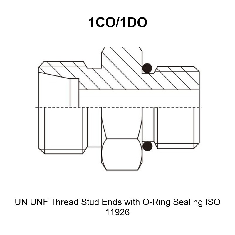
Why This UN UNF Thread Stud End O-Ring Sealing Adapter 1CO/1DO Passes the Compliance Gate
The UN UNF thread stud end O-ring sealing adapter 1CO/1DO is a straight adapter that takes a UN or UNF straight thread O-ring boss port on one end and a metric tube connection on the other. It is the standard answer for machinery that mixes port practices: an SAE-style port on the manifold, valve or cylinder, and a metric tube line running away from it.
- Stud end: UN and UNF straight thread, 7/16″X20 to 1.5/8″X12, sealed by an O-ring seated on the boss face chamfer.
- Tube end: metric male thread, M14X1.5 to M52X2, for metric tube from 8 mm to 42 mm outside diameter.
- Pressure groups taken from the drawing: 31.5 MPa and 16 MPa (light series L), 63 MPa and 40 MPa (heavy series S), plus 31.5 MPa on the largest heavy series S row.
Core Advantages
- UN UNF thread stud end O-ring sealing adapter 1CO/1DO coverage: 33 catalogue rows map UN and UNF boss ports from 7/16″X20 to 1.5/8″X12 onto metric tube from 8 mm to 42 mm.
- Straight thread O-ring sealing: the stud end seals on the boss face chamfer with an O-ring, so the joint is adjustable in rotation and can be re-positioned without deforming a taper.
- Metric tube side in the same family: the E end follows metric tube practice in the DIN 2353 / ISO 8434-1 light series L and heavy series S ranges, so no hybrid hose end is needed.
- Cross-standard integration: one part bridges an SAE J1926-1 / ISO 11926 straight thread O-ring boss port and a metric tube line, which is exactly what mixed-equipment fleets require.
- Full dimensional set: every row carries B, l1, L1, S1 and S2, so the engineer can check boss insertion depth and both hexes before ordering.
- Batch documentation: mill test reports, dimensional inspection reports and pressure test records are available per production batch on request.
Technical Specifications
What Is a UN UNF Thread Stud End O-Ring Sealing Adapter?
It is a one-piece machined steel adapter with two different male ends. The F end is a UN or UNF straight thread stud end sealed by an O-ring, matching straight thread O-ring boss port practice described by ISO 11926 and SAE J1926-1. The E end is a metric male thread that accepts a tube nut for metric tube of the outside diameter listed in the D1 column.
This is a straight thread O-ring joint, not a tapered thread joint and not a 60 degree or 74 degree cone joint. A BSPT taper stud end is not interchangeable with it, and a plain 37 degree flare stud end is not either, even when the thread looks similar.
Connection 1: UN and UNF Straight Thread Stud End with O-Ring Sealing (F)
| Attribute | Detail |
|---|---|
| End type | Straight thread stud end, O-ring sealed |
| Thread range | 7/16″X20 to 1.5/8″X12 (7/16″-20 UNF, 9/16″-18 UNF, 3/4″-16 UNF, 7/8″-14 UNF, 1.1/16″-12 UN, 1.5/16″-12 UN, 1.5/8″-12 UN) |
| Sealing method | O-ring on the boss face chamfer, captive under the hex when assembled |
| Port standard reference | ISO 11926 / SAE J1926-1 straight thread O-ring boss practice |
| O-ring | Sized to the port per the port standard for that thread, supplied fitted |
| Hex across flats | S2, per row |
| Not interchangeable with | BSPT taper threads, 60 degree seat ports, 74 degree cone stud ends, ISO 6149 O-ring stud ends |
Connection 2: Metric Male Thread for Metric Tube Nut (E)
| Attribute | Detail |
|---|---|
| End type | Metric male thread for a tube nut, straight |
| Thread range | M14X1.5 to M52X2 |
| Tube outside diameter | 8 mm to 42 mm (D1) |
| System reference | Metric tube connection practice in the DIN 2353 / ISO 8434-1 family, light series L and heavy series S |
| Hex across flats | S1, per row |
| Not interchangeable with | JIC 74 degree cone tube ends, BSP tube ends, JIS 60 degree cone tube ends |
Dimensional Data
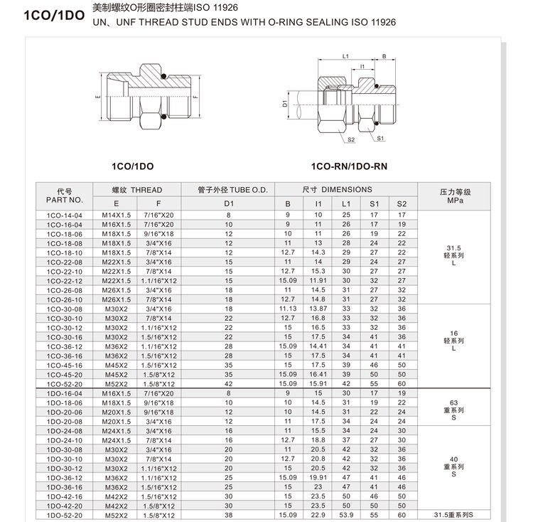
| Symbol | Signification | Unit |
|---|---|---|
| PART NO. | Catalogue ordering code | – |
| E | Metric male thread, tube nut end | – |
| F | UN / UNF straight thread stud end, O-ring sealing | – |
| D1 | Tube outside diameter | mm |
| B | Insertion depth of the stud end into the boss | mm |
| l1 | Length of the tube-end thread section | mm |
| L1 | Overall length of the adapter | mm |
| S1 | Hex across flats on the tube end | mm |
| S2 | Hex across flats on the stud end | mm |
Full Dimension Table (Part Number Matrix)
All dimensions in millimetres. Every row is transcribed from the current 1CO/1DO drawing, including the inch thread designations as printed.
| PART NO. | E THREAD | F THREAD | D1 | B | l1 | L1 | S1 | S2 | Pressure Group |
|---|---|---|---|---|---|---|---|---|---|
| 1CO-14-04 | M14X1.5 | 7/16″X20 | 8 | 9 | 10 | 25 | 17 | 17 | 31.5 MPa, light series L |
| 1CO-16-04 | M16X1.5 | 7/16″X20 | 10 | 9 | 11 | 26 | 17 | 19 | 31.5 MPa, light series L |
| 1CO-18-06 | M18X1.5 | 9/16″X18 | 12 | 10 | 11 | 26 | 19 | 22 | 31.5 MPa, light series L |
| 1CO-18-08 | M18X1.5 | 3/4″X16 | 12 | 11 | 13 | 28 | 24 | 22 | 31.5 MPa, light series L |
| 1CO-18-10 | M18X1.5 | 7/8″X14 | 12 | 12.7 | 14.3 | 29 | 27 | 22 | 31.5 MPa, light series L |
| 1CO-22-08 | M22X1.5 | 3/4″X16 | 15 | 11 | 14 | 29 | 24 | 27 | 31.5 MPa, light series L |
| 1CO-22-10 | M22X1.5 | 7/8″X14 | 15 | 12.7 | 15.3 | 30 | 27 | 27 | 31.5 MPa, light series L |
| 1CO-22-12 | M22X1.5 | 1.1/16″X12 | 15 | 15.09 | 11.91 | 30 | 32 | 27 | 31.5 MPa, light series L |
| 1CO-26-08 | M26X1.5 | 3/4″X16 | 18 | 11 | 14.5 | 31 | 27 | 32 | 31.5 MPa, light series L |
| 1CO-26-10 | M26X1.5 | 7/8″X14 | 18 | 12.7 | 14.8 | 31 | 27 | 32 | 31.5 MPa, light series L |
| 1CO-30-08 | M30X2 | 3/4″X16 | 18 | 11.13 | 13.87 | 33 | 32 | 36 | 16 MPa, light series L |
| 1CO-30-10 | M30X2 | 7/8″X14 | 22 | 12.7 | 16.8 | 33 | 32 | 36 | 16 MPa, light series L |
| 1CO-30-12 | M30X2 | 1.1/16″X12 | 22 | 15 | 16.5 | 33 | 32 | 36 | 16 MPa, light series L |
| 1CO-30-16 | M30X2 | 1.5/16″X12 | 22 | 15 | 17.5 | 34 | 41 | 36 | 16 MPa, light series L |
| 1CO-36-12 | M36X2 | 1.1/16″X12 | 28 | 15.09 | 14.41 | 34 | 41 | 41 | 16 MPa, light series L |
| 1CO-36-16 | M36X2 | 1.5/16″X12 | 28 | 15 | 17.5 | 34 | 41 | 41 | 16 MPa, light series L |
| 1CO-45-16 | M45X2 | 1.5/16″X12 | 35 | 15 | 17.5 | 39 | 46 | 50 | 16 MPa, light series L |
| 1CO-45-20 | M45X2 | 1.5/8″X12 | 35 | 15.09 | 16.41 | 39 | 50 | 50 | 16 MPa, light series L |
| 1CO-52-20 | M52X2 | 1.5/8″X12 | 42 | 15.09 | 15.91 | 42 | 55 | 60 | 16 MPa, light series L |
| 1DO-16-04 | M16X1.5 | 7/16″X20 | 8 | 9 | 15 | 30 | 17 | 19 | 63 MPa, heavy series S |
| 1DO-18-06 | M18X1.5 | 9/16″X18 | 10 | 10 | 14.5 | 31 | 19 | 22 | 63 MPa, heavy series S |
| 1DO-20-06 | M20X1.5 | 9/16″X18 | 12 | 10 | 14.5 | 31 | 22 | 24 | 63 MPa, heavy series S |
| 1DO-20-08 | M20X1.5 | 3/4″X16 | 12 | 11 | 17.5 | 34 | 24 | 24 | 63 MPa, heavy series S |
| 1DO-24-08 | M24X1.5 | 3/4″X16 | 16 | 11 | 15.5 | 34 | 24 | 30 | 40 MPa, heavy series S |
| 1DO-24-10 | M24X1.5 | 7/8″X14 | 16 | 12.7 | 18.8 | 37 | 27 | 30 | 40 MPa, heavy series S |
| 1DO-30-08 | M30X2 | 3/4″X16 | 20 | 11 | 20.5 | 42 | 32 | 36 | 40 MPa, heavy series S |
| 1DO-30-10 | M30X2 | 7/8″X14 | 20 | 12.7 | 20.8 | 42 | 32 | 36 | 40 MPa, heavy series S |
| 1DO-30-12 | M30X2 | 1.1/16″X12 | 20 | 15 | 20.5 | 42 | 32 | 36 | 40 MPa, heavy series S |
| 1DO-36-12 | M36X2 | 1.1/16″X12 | 25 | 15.09 | 19.91 | 47 | 41 | 46 | 40 MPa, heavy series S |
| 1DO-36-16 | M36X2 | 1.5/16″X12 | 25 | 15 | 23 | 47 | 41 | 46 | 40 MPa, heavy series S |
| 1DO-42-16 | M42X2 | 1.5/16″X12 | 30 | 15 | 23.5 | 50 | 46 | 50 | 40 MPa, heavy series S |
| 1DO-42-20 | M42X2 | 1.5/8″X12 | 30 | 15 | 23.5 | 50 | 50 | 50 | 40 MPa, heavy series S |
| 1DO-52-20 | M52X2 | 1.5/8″X12 | 38 | 15.09 | 22.9 | 53.9 | 55 | 60 | 31.5 MPa, heavy series S |
Reading the table: E is the metric tube-end thread that matches D1, F is the inch stud thread that matches the port, and the pressure group applies to the whole row.
Thread Size and Dash Chart
| F Thread (stud end) | E Thread (tube end) | Tube O.D. D1 | Catalogue Row | Pressure Group |
|---|---|---|---|---|
| 7/16″X20 (7/16″-20 UNF) | M14X1.5 | 8 | 1CO-14-04 | 31.5 MPa, L |
| 7/16″X20 (7/16″-20 UNF) | M16X1.5 | 10 | 1CO-16-04 | 31.5 MPa, L |
| 9/16″X18 (9/16″-18 UNF) | M18X1.5 | 12 | 1CO-18-06 | 31.5 MPa, L |
| 3/4″X16 (3/4″-16 UNF) | M18X1.5 | 12 | 1CO-18-08 | 31.5 MPa, L |
| 7/8″X14 (7/8″-14 UNF) | M22X1.5 | 15 | 1CO-22-10 | 31.5 MPa, L |
| 1.1/16″X12 (1-1/16″-12 UN) | M22X1.5 | 15 | 1CO-22-12 | 31.5 MPa, L |
| 3/4″X16 (3/4″-16 UNF) | M30X2 | 18 | 1CO-30-08 | 16 MPa, L |
| 1.5/16″X12 (1-5/16″-12 UN) | M30X2 | 22 | 1CO-30-16 | 16 MPa, L |
| 1.5/8″X12 (1-5/8″-12 UN) | M52X2 | 42 | 1CO-52-20 | 16 MPa, L |
| 7/16″X20 (7/16″-20 UNF) | M16X1.5 | 8 | 1DO-16-04 | 63 MPa, S |
| 3/4″X16 (3/4″-16 UNF) | M20X1.5 | 12 | 1DO-20-08 | 63 MPa, S |
| 7/8″X14 (7/8″-14 UNF) | M24X1.5 | 16 | 1DO-24-10 | 40 MPa, S |
| 1.1/16″X12 (1-1/16″-12 UN) | M30X2 | 20 | 1DO-30-12 | 40 MPa, S |
| 1.5/8″X12 (1-5/8″-12 UN) | M42X2 | 30 | 1DO-42-20 | 40 MPa, S |
| 1.5/8″X12 (1-5/8″-12 UN) | M52X2 | 38 | 1DO-52-20 | 31.5 MPa, S |
Note how many port sizes a single tube side can serve: 3/4″-16 UNF appears with M18X1.5, M20X1.5 and M30X2 tube ends in this matrix.
Matériaux et traitements thermiques
| Article | Specification | Status |
|---|---|---|
| Body material | Carbon steel, machined from bar | Typical |
| Alternative material | Stainless steel on request | On request |
| Heat treatment | Stress relief / hardening per part size and pressure group | Typical |
| Surface treatment | Zinc plating with trivalent passivation; other finishes on request | Typical |
| O-ring material | Standard boss O-ring compound; alternative compounds on request | Typical |
| Thread inspection | Go / no-go gauge check on both metric and inch threads | Typical |
| Documentation | Mill test report, dimensional report, pressure test record | On request |
Working Pressure and Operating Envelope
Working pressure is set by the pressure group of the row selected, together with the tube system and hose assembly the adapter joins.
| Group from Drawing | Série | Typical Application Envelope |
|---|---|---|
| 31.5 MPa | Light series L | Light-series metric tube lines, D1 8-18 mm |
| 16 MPa | Light series L | Light-series lines with larger tube, D1 18-42 mm |
| 63 MPa | Heavy series S | High-pressure heavy-series lines, D1 8-12 mm |
| 40 MPa | Heavy series S | Heavy-series lines, D1 16-30 mm |
| 31.5 MPa | Heavy series S | Largest heavy-series row, D1 38 mm |
The finished assembly is only as strong as its weakest member, so the tube, nut, ferrule or cone and hose must be rated at or above the row’s group. (1 MPa is approximately 145 psi.)
Temperature Range
| Condition | Range | Remarques |
|---|---|---|
| Prestation type | -40 °C to +120 °C | Governed by the O-ring compound and the hose or tube selected |
| O-ring compound | Standard boss O-ring compound | Alternative compounds on request |
| Low temperature | Below -40 °C | Confirm a low-temperature O-ring compound before order |
| High temperature | Above +120 °C | Confirm a high-temperature O-ring compound before order |
How to Read the Part Number Matrix
The ordering code follows: series prefix, tube-end thread code, stud-end thread code. Prefix tells you light or heavy series, the first block is the metric tube thread, and the second block is the inch boss thread code.
- Prefix 1CO = light series; prefix 1DO = heavy series.
- First block: metric tube thread nominal diameter (14 = M14X1.5).
- Second block: inch boss thread code (04 = 7/16″X20, 06 = 9/16″X18, 08 = 3/4″X16, 10 = 7/8″X14, 12 = 1.1/16″X12, 16 = 1.5/16″X12, 20 = 1.5/8″X12).
Example 1: 1CO-14-04 = light series, metric tube end M14X1.5 for 8 mm tube, 7/16″X20 UNF boss stud end, 31.5 MPa group.
Example 2: 1CO-22-12 = light series, metric tube end M22X1.5 for 15 mm tube, 1.1/16″X12 UN boss stud end, 31.5 MPa group. Here the boss thread is only one size above the tube thread, a common pairing on compact manifolds.
Example 3: 1DO-42-20 = heavy series, metric tube end M42X2 for 30 mm tube, 1.5/8″X12 UN boss stud end, 40 MPa group.
Selection and Ordering
Ordering the UN UNF thread stud end O-ring sealing adapter 1CO/1DO is a four-step check: identify the boss thread, note the boss face type, match the metric tube size, then compare the pressure group.
Selection Checklist and Decision Table
| Question | Answer | Consequence |
|---|---|---|
| What is the boss thread on the port? | Match to F exactly | A UNF and a UN thread of similar size are not interchangeable |
| Is the port a straight thread O-ring boss? | Yes = this series is suitable | A BSPT taper port needs a different stud end |
| Is the O-ring present and correctly sized? | Check before assembly | A wrong or missing O-ring leaks at low pressure |
| What is the metric tube outside diameter? | Match to D1 | Determines the E thread row |
| Which series does the tube system use? | Light L or heavy S | Determines 1CO versus 1DO and the pressure group |
| What is the system working pressure? | Compare with group | A 16 MPa row must not be used on a 31.5 MPa line |
Cross Reference Service
Send a photo or a dimension sketch of the adapter being replaced, or the old marking if readable. We measure both threads with metric and inch gauges, check the boss seat and record B, l1, L1, S1 and S2, then map the part to a 1CO/1DO row, free of charge. We do not copy or re-badge another manufacturer’s part number.
Emballage et logistique
| Article | Standard Practice |
|---|---|
| Unit protection | Individually bagged with the stud thread protected |
| Carton marking | Part number, batch number, quantity, pressure group |
| Spare O-rings | Boss O-rings can be supplied in the same shipment for service stock |
| Documentation | Mill test report and dimensional report travel with the batch on request |
| Mixed shipping | Mixed sizes combined in one shipment to control freight cost |
| Urgent orders | Air freight for urgent replacement quantities |
Installation and Fitment Guide
Step-by-Step Assembly
- Confirm the boss thread designation, the tube size and the pressure group against your order before opening the packaging.
- Clean the boss threads, the boss face chamfer and the O-ring seat. Any swarf in the chamfer will cut the O-ring at assembly.
- Fit a new, correctly sized O-ring and check that it sits on the seat without twisting or rolling.
- Screw the stud end in by hand until the O-ring contacts the chamfer, then torque to the value for that thread size and material class.
- Hold the stud end at its hex while tightening the tube nut on the metric side, so the boss joint is not disturbed.
- Pressurise gradually and check both ends for weeping before the machine returns to service.
Torque and Sealing Notes
- Use the torque table for the exact thread size, material class and finish involved, taken from the applicable standard data sheet or the drawing supplied with the order. Do not apply one blanket figure across both ends.
- An O-ring boss joint seals on the chamfer, not on the threads. Thread sealant is not required and can interfere with the O-ring seat.
- Straight thread O-ring boss joints hold by clamping, so the stud end can be oriented before final tightening. Snug it first, position the assembly, then torque.
- Never re-use an O-ring that has taken a set, been nicked or been exposed to the wrong fluid.
- If a joint weeps at low pressure but holds at high pressure, check the O-ring size and the boss face chamfer before increasing torque.
Installation Warnings
- Do not fit this stud end into a BSPT or NPT taper port, and do not fit a taper stud into an O-ring boss port.
- Do not interchange UN and UNF threads of a similar nominal size; they have different pitches and will not seal.
- Do not substitute an ISO 6149 metric O-ring stud end, a 60 degree seat stud end or a 74 degree cone stud end for this part.
- Do not omit the O-ring, and do not substitute one of a different size or hardness.
- Do not use the tube-end hex to tighten the stud end, or the boss seal can be disturbed.
- Do not exceed the pressure group of the selected row.
Applications and Industries
Cross-standard equipment integration: the most common use is a machine with an SAE-style O-ring boss port feeding a metric tube line, which is routine on mixed European and North American equipment fleets.
Repair and replacement: the boss thread and tube size on the old part are normally still readable, so the matrix can be used to identify a replacement row quickly.
High-pressure test benches: the 63 MPa and 40 MPa heavy series rows suit rigs that need an SAE-style port with a metric tube run.
Oil and gas equipment: valve packages, manifolds, accumulators and actuator lines that use straight thread O-ring boss ports.
Construction and mining machinery: hydraulically actuated implements and hose runs where service parts must come from a standard matrix.
Industrial plant: presses, power units and machine tools that mix port standards after a retrofit or an upgrade.
Industry tags: hydraulic adapter, UNF stud end, O-ring boss, ISO 11926, SAE J1926-1, DIN 2353, ISO 8434-1, tube adapter, hydraulic fitting.
OEM Customization and Quality Traceability
We manufacture hydraulic adapters and hose assemblies and support OEM programs with private labelling and laser marking of your own part number on the hex or shank. Custom finishes, non-standard lengths, special O-ring compounds and mixed-thread configurations are quoted from your drawing or sample, usually within 24 hours.
Each production batch is traceable. Parts pass a 100 percent pressure test before packing, and mill test reports, dimensional inspection reports and pressure test records are available with the shipment on request. Third-party inspection such as BV or SGS can be arranged. Our manufacturing system is certified to ISO 9001:2015 and ISO 18752.
FAQ
Q: What port standard does this adapter’s stud end match?
A: The stud end is a UN or UNF straight thread sealed by an O-ring on the boss face chamfer, matching straight thread O-ring boss practice described by ISO 11926 and SAE J1926-1.
Q: Can I use a UN UNF thread stud end O-ring sealing adapter 1CO/1DO on a BSPT port?
A: No. A BSPT port is tapered and seals on the threads, while this stud end is straight and seals on the boss chamfer with an O-ring. The two are not interchangeable even when a thread appears to start.
Q: How do I know which O-ring is needed?
A: The O-ring is determined by the boss thread size and the port standard for that thread, not by the tube size. State the boss thread when ordering and we confirm the O-ring that is fitted, or supply spare rings for service stock.
Q: What is the difference between the 1CO and 1DO rows?
A: 1CO rows are light series metric tube ends and 1DO rows are heavy series metric tube ends. The same inch boss thread, for example 3/4″-16 UNF, appears in both, but the tube thread, wall and pressure group differ.
Q: What pressure can this adapter take?
A: The drawing groups the rows at 31.5 MPa and 16 MPa for light series L, 63 MPa and 40 MPa for heavy series S, and 31.5 MPa on the largest heavy series S row.
Q: Is thread sealant needed on the stud end?
A: No. The joint seals on the boss face chamfer through the O-ring, so thread sealant is not required and can contaminate the seal area.
Q: Can the stud end be rotated after installation to clock the tube run?
A: Yes. A straight thread O-ring boss joint clamps on the chamfer, so the stud end can be positioned before final torque, which is useful where the tube route must clear other components.
Q: What are your lead times and documentation options?
A: Standard rows typically ship as a 7-day batch, custom sampling is available in about 48 hours for new drawings, and urgent quantities can be air freighted. Mill test reports and dimensional records travel with the batch on request.
Demander un devis
Send us the boss thread designation, the port type, the metric tube outside diameter, the series (light L or heavy S) and the quantity. With those five details we confirm the correct row of the UN UNF thread stud end O-ring sealing adapter 1CO/1DO matrix, check the pressure group and O-ring, and return a quotation within 24 hours.
Browse the full Adaptateurs hydrauliques range for the complete family, or contact us to request a quote, mill test reports, and samples.


 English
  Spanish
  Portuguese
  French
  German
  Arabic