
87311-RW SAE Flange Fitting 3000 PSI
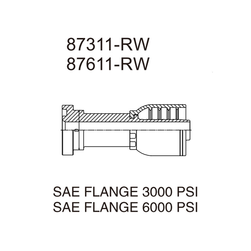
Our SAE flange fitting 3000 psi, series 87311-RW, is a crimp-on hydraulic hose fitting with an SAE J518 Code 61 four-bolt flange head. It connects braided hydraulic hose to SAE flange ports on pumps, valve manifolds and cylinders used in heavy hydraulic systems. The range covers 1/2″ to 2.1/2″ flange sizes, dash size -08 to -40, hose bore DN12 to DN64. Every fitting is 100% dimensionally inspected before shipment.
Conformité et normes :
- SAE J518 Code 61 (four-bolt flange, 3000 psi series)
- ISO 6162 (flange connections for fluid power)
- ISO 12151-3 (hose fittings with flange ends)
- SAE J516 (norme de référence générale relative à la conception des raccords pour flexibles hydrauliques)
Pourquoi les acheteurs choisissent ce modèle :
- The heavy-duty connection. Four-bolt flange joints are the standard choice for large bore, high flow hydraulic lines where threaded connections become impractical.
- O-ring face seal. The flange face carries an O-ring groove. The compressed O-ring seals against the mating flange face, with no metal-to-metal fit-up and no leakage under impulse.
- Full flange size range. 1/2″ through 2.1/2″ (SAE J518 Code 61), covering flange ports from DN12 to DN64.
- Large plage de températures. Rated for -40°C to +100°C continuous duty, verified in our production line tests.
SAE Flange Fitting 3000 PSI Technical Specifications
The table below lists all 15 sizes of the 87311-RW SAE flange fitting 3000 psi. Dimensions are in millimeters. Flange dimensions follow SAE J518 Code 61. Dim. A is the length from the flange face to the hose-end shoulder, Dim. C is the flange head outside diameter, Dim. D is the bolt hole center distance, and Dim. L is the flange head thickness.
| Référence. | Flange Size | Diamètre intérieur du tuyau DN (mm) | Taille du tiret | Dim. A (mm) | Dim. C (mm) | Dim. D (mm) | Dim. L (mm) |
|---|---|---|---|---|---|---|---|
| 87311-08-08RW | 1/2″ | 12 | -08 | 46.0 | 30.2 | 24.0 | 6.73 |
| 87311-12-08RW | 3/4″ | 12 | -08 | 47.0 | 38.1 | 31.7 | 6.73 |
| 87311-12-10RW | 3/4″ | 16 | -10 | 48.0 | 38.1 | 31.7 | 6.73 |
| 87311-12-12RW | 3/4″ | 20 | -12 | 48.0 | 38.1 | 31.7 | 6.73 |
| 87311-12-16RW | 3/4″ | 25 | -16 | 49.0 | 38.1 | 31.7 | 6.73 |
| 87311-16-12RW | 1″ | 20 | -12 | 51.0 | 44.4 | 38.0 | 8.00 |
| 87311-16-16RW | 1″ | 25 | -16 | 52.0 | 44.4 | 38.0 | 8.00 |
| 87311-16-20RW | 1″ | 32 | -20 | 53.0 | 44.4 | 38.0 | 8.00 |
| 87311-20-16RW | 1.1/4″ | 25 | -16 | 57.0 | 50.8 | 43.0 | 8.00 |
| 87311-20-20RW | 1.1/4″ | 32 | -20 | 58.0 | 50.8 | 43.0 | 8.00 |
| 87311-24-20RW | 1.1/2″ | 32 | -20 | 68.0 | 60.3 | 50.0 | 8.00 |
| 87311-24-24RW | 1.1/2″ | 40 | -24 | 68.0 | 60.3 | 50.0 | 8.00 |
| 87311-32-24RW | 2″ | 40 | -24 | 70.0 | 71.4 | 62.0 | 9.53 |
| 87311-32-32RW | 2″ | 50 | -32 | 70.0 | 71.4 | 62.0 | 9.53 |
| 87311-40-40RW | 2.1/2″ | 64 | -40 | 76.0 | 84.1 | 74.0 | 9.53 |
Notes: Dim. C (flange O.D.) and Dim. D (bolt spacing) match the SAE J518 Code 61 standard exactly, so these fittings bolt directly onto any Code 61 flange port. The -RW suffix denotes the braided-hose version; for spiral-wound hose, use series 87312-XX-XXRW.
Why Flange Connections for Big Lines
When the hose bore grows beyond about DN32, threaded connections become heavy, awkward and hard to torque reliably. The four-bolt flange solves this: the joint is clamped with four bolts, the O-ring on the flange face carries the seal, and the connection is assembled with ordinary wrenches instead of torque multiplication tools.
This SAE flange fitting 3000 psi is the standard solution for pump suction and discharge lines, valve manifold connections and reservoir lines in mobile and industrial hydraulics. The Code 61 flange pattern (3000 psi series) is the most widely used flange standard in the world, so this fitting mates directly with existing flange ports without adapters.
How the Flange O-Ring Seals
The flange face of this fitting carries an O-ring groove. When the four bolts are tightened, the O-ring is compressed between this flange face and the mating flange face of the port. The O-ring, not the metal faces, carries the seal. This is the same face-seal philosophy as the ORFS system, scaled up for large bores and high flow rates.
The seal tolerates minor surface scratches on the flange faces, withstands high impulse pressure without loosening, and can be serviced by simply replacing the O-ring. Our impulse testing found that flange assemblies hold pressure cycling reliably across the full temperature range.
Profondeur d'insertion et diamètre extérieur du sertissage : les deux chiffres demandés par les ingénieurs
La profondeur d'insertion correspond à la longueur de la partie cannelée qui pénètre dans l'alésage du tuyau. Le diamètre extérieur après sertissage correspond au diamètre extérieur de la virole après sertissage. Ces deux paramètres déterminent ensemble si l'ensemble résiste à la pression ou présente des fuites au niveau de la zone de sertissage.
HENGHUA publie les valeurs correspondantes de profondeur d’insertion et de diamètre extérieur de sertissage pour chaque type de flexible que nous fournissons, y compris les modèles SAE 100 R1AT, R2AT et EN 853 1SN / 2SN. Ces valeurs sont spécifiques à chaque flexible, car l’épaisseur du renfort influe sur l’épaisseur totale. Demandez notre fiche technique de sertissage en indiquant le modèle de votre flexible et nous vous communiquerons le diamètre extérieur exact du sertissage ainsi que le choix de la matrice dans un délai d’un jour ouvré.
Nos essais de production ont montré qu’un diamètre extérieur de sertissage vérifié et compris dans la tolérance publiée (généralement ± 0,2 mm) offre une marge de sécurité contre l’éclatement de 4:1 ou plus sur l’ensemble complet. Effectuez une mesure à l’aide d’un pied à coulisse numérique après chaque sertissage.
Matériaux et traitements thermiques
- Acier au carbone (standard) : high-strength cold-headed or hot-forged carbon steel (20# / 35# / 45# grades). The tail and flange are case-hardened with a carburizing and quenching process for fatigue resistance. Reference hardness range is HRC 20-28 on the core with a hardened case.
- Finition de surface : Zingage blanc ou de couleur (jaune) avec passivation. Des revêtements en zinc-nickel et Dacromet sont disponibles en option pour répondre à des exigences plus strictes en matière de test au brouillard salin.
- Acier inoxydable (en option) : 304, 316 or 316L stainless steel for corrosive media and washdown environments.
Valeurs nominales de pression et de température
The connection rating follows the SAE J518 Code 61 reference table below. These are reference values (§) for the fitting connection itself. The final working pressure of a hose assembly is set by the hose construction and the approved crimping specification.
| Flange Size | Diamètre intérieur du tuyau DN (mm) | Reference Connection Pressure (bar)§ |
|---|---|---|
| 1/2″ to 1″ | 12 to 32 | 207 |
| 1.1/4″ to 1.1/2″ | 25 to 40 | 172 |
| 2″ | 40 to 50 | 138 |
| 2.1/2″ | 64 | 103 |
§Reference values per SAE J518 Code 61 (3000 psi series) connection classes. Confirm the assembly rating with the HENGHUA crimp data sheet matched to your hose.
Plage de températures : -40°C to +100°C for the fitting in continuous service. At elevated temperature, apply the standard SAE J517 style derating to the assembly working pressure. Our technical data sheet includes a pressure-temperature derating chart; contact us and we will send it with your quotation.
Essais de pression : HENGHUA est en mesure de fournir des ensembles ayant subi des essais de résistance jusqu'à 100% de la pression de service nominale, avec des certificats d'essai sur demande.
How to Select the Right SAE Flange Fitting 3000 PSI
Selection is a three-step process. First, match the hose bore to the dash size. Second, match the flange size to your port. Third, confirm the hose construction version (-RW for braided, 87312 series for spiral).
Structure des références
Lisez toute référence HENGHUA en trois segments. Exemple : 87311-16-16RW.
| Segment | Valeur | Signification |
|---|---|---|
| Série | 87311 | SAE flange fitting, 3000 psi (Code 61) |
| Flange code | 16 | 1″ flange (the number is the flange size code) |
| Taille des tirets | 16 | Hose bore DN25, dash -16 |
| Suffixe | RW | Braided hose version (spiral hose uses 87312 series) |
Sélectionner par série de tuyaux
The 87311-RW fitting is designed for braided hydraulic hose. Recommended matching constructions:
- SAE 100 R1AT (one wire braid) – for -08 to -40 sizes
- SAE 100 R2AT (two wire braid) – for -08 to -40 sizes
- EN 853 1SN et 2SN (constructions européennes équivalentes)
- Spiral constructions (EN 856 4SP / 4SH) – use the 87312 series version
Select by Flange Size
The flange head follows the SAE J518 Code 61 pattern, which bolts directly onto standard Code 61 flange ports:
- Petites tailles : 1/2″ and 3/4″ flange (dash -08 to -16)
- Tailles moyennes : 1″ and 1.1/4″ flange (dash -12 to -20)
- Grandes tailles : 1.1/2″, 2″ and 2.1/2″ flange (dash -20 to -40)
Assembly uses four standard bolts (not supplied) and the O-ring on the flange face. Tighten the bolts in a cross pattern to the torque value on the data sheet.
Références croisées
This series replaces equivalent SAE J518 Code 61 flange fittings available in the market. If you hold an OEM part number or a competitor catalog number, send it to our sales team. We confirm the direct replacement within 24 hours, including flange size, dash size and insert depth checks.
Emballage et logistique
| Article | Emballage standard pour l'exportation |
|---|---|
| Unité d'emballage | 10 pièces par boîte intérieure (petites tailles), 5 pièces par boîte (grandes tailles) |
| Carton d'emballage extérieur | Carton ondulé à 5 couches de qualité export, 10 boîtes par carton |
| Poids | Poids net et brut par taille, tels qu'indiqués dans notre devis |
| Origine | Chine (usine de HENGHUA) |
| Délai de livraison | Les articles en stock sont expédiés sous 7 jours ; les articles fabriqués sur commande, sous 15 à 25 jours. |
| Paiement | Paiement par virement bancaire (T/T), lettre de crédit (L/C) et assurance commerciale acceptés |
Guide de montage : quatre étapes pour un montage sûr du tuyau
Follow this process for every crimped assembly. It applies to every SAE flange fitting 3000 psi size from dash -08 to -40. Skipping one step is the most common cause of early fitting failure.
Étape 1 – Coupez le tuyau à angle droit. Utilisez un coupe-tuyau bien affûté. Une coupe à bords droits permet au raccord de s'emboîter uniformément dans le tuyau. Une coupe biseautée ou irrégulière laisse des espaces vides qui peuvent devenir des points de fuite.
Étape 2 – Marquez la profondeur d'insertion. Mesurez la profondeur d'insertion indiquée dans la fiche technique de sertissage HENGHUA. Tracez une ligne sur la gaine du tuyau à cette distance. Le repère doit rester visible après l'insertion.
Étape 3 – Lubrifiez et insérez. Appliquez une fine couche de lubrifiant de montage compatible à l'intérieur du tuyau et sur l'extrémité cannelée du raccord. Enfoncez le raccord en effectuant un mouvement de rotation jusqu'à ce que le repère de profondeur s'aligne avec l'extrémité du raccord. Arrêtez-vous au niveau du repère. Ne forcez pas au-delà.
Étape 4 – Sertir et vérifier. Choisissez le jeu de matrices adapté à la taille de votre flexible et de votre raccord. Effectuez le sertissage d’un seul mouvement continu. Une fois le sertissage terminé, mesurez le diamètre extérieur (DE) du sertissage à l’aide d’un pied à coulisse numérique et comparez-le à la tolérance indiquée sur la fiche technique du sertissage. Notez la valeur dans votre registre de qualité. Un diamètre extérieur de sertissage correct fait toute la différence entre un assemblage qui durera 10 ans et une défaillance sur le terrain.
Consignes de sécurité – À lire avant de procéder au sertissage
- Ne mélangez jamais les marques. Les flexibles et les raccords de différents fabricants peuvent présenter les mêmes dimensions, mais utiliser des paramètres de sertissage différents. Veillez à toujours utiliser un ensemble flexible, raccord et fiche technique de sertissage compatibles.
- Never seal the flange face with tape. The O-ring in the flange groove carries the seal. Thread sealant tape or paste on the flange face destroys the seal.
- Vérifiez le joint torique avant le montage. A cut, pinched or hardened O-ring must be replaced. Never assemble the flange without it.
- Do not mix Code 61 and Code 62 flanges. Code 62 (6000 psi) flanges look similar but have different dimensions. This series is Code 61 (3000 psi); never bolt it onto a Code 62 port.
- Tighten bolts in a cross pattern. Tighten the four bolts alternately to the torque value on the data sheet to keep the O-ring evenly compressed.
- Never reuse a crimped fitting. Once crimped, the ferrule zone is work-hardened. A re-crimp cannot restore the original grip.
OEM Customization and Quality Traceability
HENGHUA supplies not only standard sizes but also fully customized SAE flange fitting solutions for OEM programs.
Customization Services
- Flange and tail customization. Special flange patterns, custom tail lengths, and non-standard hose-end dimensions for your hose construction.
- O-ring elastomer selection. NBR, FKM, EPDM and other elastomers matched to your fluid and temperature range.
- Surface treatment customization. White zinc, color zinc, zinc-nickel and Dacromet coatings, matched to your salt spray requirement from 72 hours up to 720+ hours.
- Laser marking. Your logo, part number and batch code laser-marked on the flange for full traceability.
- Packaging customization. Private-label boxes, barcode labels and mixed-size kits per your BOM.
Quality Traceability
Every HENGHUA batch carries a traceable batch number. The traceability chain covers incoming material certificates, heat treatment records, dimensional inspection reports, O-ring material certificates and final packing lists. Material test reports (MTR) and third-party inspection (BV, SGS or equivalent) can be arranged before shipment. Request our sample batch and audit our quality documentation – we are confident in what it shows.
Foire aux questions
What is an SAE flange fitting 3000 psi?
It is a hydraulic hose fitting with an SAE J518 Code 61 four-bolt flange head and an O-ring groove on the flange face. It connects large bore hose to standard Code 61 flange ports. The system follows ISO 6162 and ISO 12151-3.
What is the difference between Code 61 and Code 62 flanges?
Code 61 is the 3000 psi series; Code 62 is the 6000 psi series with larger dimensions for the same nominal size. This fitting is Code 61. Never bolt a Code 61 flange onto a Code 62 port.
How does the flange seal?
The O-ring in the flange face groove is compressed between the two flange faces when the four bolts are tightened. The O-ring, not the metal faces, carries the seal.
Which hose works with the 87311-RW fitting?
The 87311-RW version is designed for braided hydraulic hose such as SAE 100 R1AT, R2AT and EN 853 1SN / 2SN. For spiral-wound hose, use the 87312 series.
Do you supply stainless steel versions?
Yes. 304, 316 and 316L stainless steel versions are available for the full size range, with the same dimensions and crimp behavior.
What is the minimum order quantity?
Stock sizes start from 100 pcs. Customized versions start from 500 pcs per size. OEM annual contracts can be discussed directly with our factory team.
Get a Quote for Your SAE Flange Fitting 3000 PSI
Tell us your hose model, flange size and annual volume. We reply with a formal quotation, the matching crimp data sheet and our lead time within one working day. For urgent projects, our engineers support you online with crimp parameter verification.
Inquiry for Our Product
We are a global supplier of hydraulic fittings and equipment, serving a wide range of sectors with a one-stop sourcing solution. Our products include hydraulic hoses, fittings, adapters, quick couplers, connectors, hose guard, hydraulic equipment and more-everything you need to keep your operations running smoothly and efficiently.
Tell us your requirements using the form below. Our team will respond with expert guidance and a customized quote to keep your operations running smoothly.
- Tuyau hydraulique2727 products
- Tuyau hydraulique à spirale en fil d'acier66 products
- Tuyau hydraulique tressé en fil d’acier1010 products
- Tuyau hydraulique renforcé de tissu33 products
- Tuyau hydraulique thermoplastique33 products
- Tuyau industriel5959 products
- Tuyau à air99 products
- Tuyau d'arrosage1111 products
- Tuyau d'huile1616 products
- Tuyau pour produits chimiques66 products
- Tuyau à vapeur33 products
- Tuyau polyvalent22 products
- Tuyaux pour l'agroalimentaire44 products
- Tuyau pour béton44 products
- Tuyau à ciment22 products
- Tuyau pour la manutention de matériaux1111 products
- Tuyau de dragage44 products
- Raccords hydrauliques162162 products
- Raccords de tuyaux réutilisables66 products
- Raccords de tuyau sans emboîtement88 products
- Raccords hydrauliques JIC1515 products
- Raccords hydrauliques métriques3838 products
- Raccords hydrauliques NPT66 products
- Raccords hydrauliques BSP2626 products
- Raccords hydrauliques SAE3030 products
- Raccords hydrauliques de type « banjo »44 products
- Raccords hydrauliques ORFS1111 products
- Embout1111 products
- Raccords à bride2626 products
- Raccords monoblocs2323 products
- Adaptateurs hydrauliques9494 products

 English
  Spanish
  Portuguese
  French
  German