
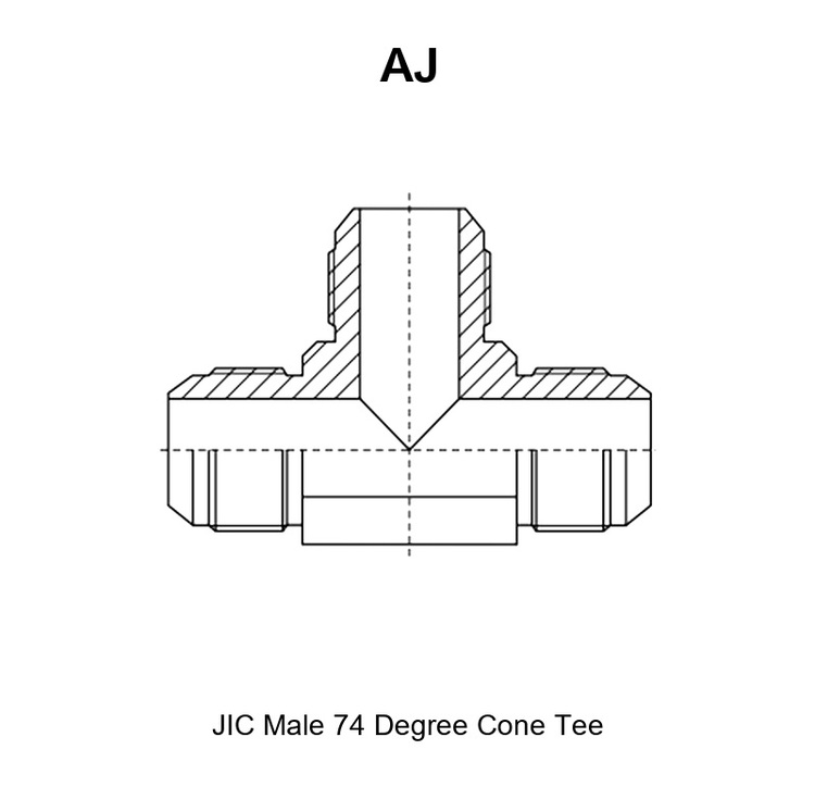
The AJ adapter is a JIC male 74° cone tee: a three-port branch fitting with a male 74° cone stud end on each of its three legs, made to the SAE J514 JIC sealing system. Two of the three legs sit in line as the run, and the third leg stands at 90° from the run as the branch. It divides one line into two, or brings two lines together into one, without any change of standard at the joint.
All three cone ends must match the seats they enter exactly in thread size and cone angle, because that is the precondition for eliminating leakage at all three joints of the same part. Each leg also needs its own nut and sleeve on the tube side, and those are ordered separately from the tee.
Sealing principle of this series: every leg ends in a 74° external cone that seats metal-to-metal on the 74° internal cone of the mating seat. No elastomer sits in the sealing path of any leg, no thread sealant is used, and the seal depends on the three cones being clean, concentric and undamaged.
Core Advantages
- Three male 74° cone ends in one body, so a single part carries flow in two directions from one point.
- Equal-ended rows from 7/16″x20 to 2.1/2″x12, plus reducing rows that branch a smaller line off a larger run.
- Metal-to-metal 74° cone seal on every leg, with no elastomer to age, swell or extrude.
- Body hex from 11 mm to 63 mm across flats, so the tee can be held while each nut is tightened.
- Carbon steel with trivalent chromium zinc plating; 304 or 316 stainless steel for corrosive and offshore service.
- Every batch checked against the drawing with thread gauges before packing.
1. What an AJ Adapter Does
An AJ adapter is a tee adapter with three JIC male 74° cone ends. It is fitted between tube assemblies: the two in-line legs carry the run, and the third leg carries the branch, so the part splits one line into two or joins two lines into one at a single point.
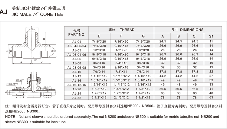
The three ports are printed in table 2.5 as E, F and G. Port E is the first run end and port G is the second run end, so E and G lie on one axis. Port F is the branch end, standing at 90° to that axis. In this series the three legs are dimensioned as A, B and C on the drawing: A is the length from the E end face to the branch axis, C is the length from the G end face to the branch axis, and B is the branch height, measured from the run axis to the F end face.
Buyers who compare the tee families in this catalogue ask how a run tee adapter and a branch tee adapter differ. A run tee adapter keeps its two in-line ports on the run and takes the third port off the run centre, so it drops into a straight line and a third line leaves at 90°; in the printed table of the CJ series the two run legs are dimensioned in the A and B columns and the branch leg in the C column. A branch tee adapter is the same three-port body arranged so that the branch is the leg the table dimensions in the B column, with the two remaining legs in A and C, as in the BJ series. The sealing system is the same on both, so the practical difference is which leg faces the line being fed.
One more point decides whether a JIC adapter tee can be used at all: the AJ adapter is not a bulkhead part. It has no panel stem and no lock nut, and a line that has to pass through a panel uses the AJ6JJ bulkhead branch tee. Every leg of the AJ adapter also needs a nut and sleeve, and those are ordered separately.
2. AJ Specifications
2.1 Connection 1 – the two in-line run ends (E and G)
- Thread standard and family: SAE J514, JIC 74° cone seat family, straight inch thread.
- Thread size range available: 7/16″x20 to 2.1/2″x12 on the run legs, in the steps printed in table 2.5.
- Gender: male stud ends at both run legs.
- Sealing method: 74° external cone seating metal-to-metal on the mating 74° internal cone.
- Mating port standard: SAE J514 74° cone seat, made up with the nut and sleeve that match the tube size.
2.2 Connection 2 – the branch end (F)
- Thread standard and family: SAE J514, JIC 74° cone seat family, straight inch thread.
- Thread size range available: 7/16″x20 to 2.1/2″x12. In a reducing part this leg carries the size printed in the F column.
- Gender: male stud end at the branch.
- Sealing method: 74° external cone seating metal-to-metal on the mating 74° internal cone.
- Mating port standard: SAE J514 74° cone seat, made up with the matching nut and sleeve for the tube.
Connections 1 and 2 are the same family and sealing type, and the difference between them is position rather than standard. Read the E, F and G columns together with the A, B and C lengths, and confirm which leg is the branch before ordering a reducing part.
2.3 Construction and Materials
The body of this hydraulic fitting adapter is machined from bar stock on CNC lathes, with the three cones, the three threads and the centre hex turned so that the run legs stay on one axis and the branch stays square to it. That squareness lets all three tube assemblies land without side load.
- Body material: carbon steel as standard; 304 stainless steel or 316 stainless steel on request; brass for selected sizes.
- Plating and finish: trivalent chromium zinc plating (Cr3+) for carbon steel as standard; zinc-nickel plating available. Plating thickness and corrosion performance are confirmed per order.
- Seal material options: the 74° cone joint is metal-to-metal, so the tee itself carries no elastomer. Where the same circuit uses elastomer-sealed components, NBR, FKM and EPDM are the available compounds.
- Machining process: bar-stock turning, thread forms produced to the SAE J514 seat geometry, cones checked against the drawing.
- Hex feature: one centre hex (S1) on the body, from 11 mm to 63 mm across flats depending on size. There is no bulkhead feature in this series.
2.4 Pressure and Temperature
Working pressure is not set by the series code. It is governed by the thread size, the wall thickness of the tee and of the tubes it joins, the sealing method and the material selected for the hydraulic adapter body. Working pressure for these sizes is confirmed per order by HENGHUA engineering, based on the thread size, sealing method and material selected.
Temperature is a material fact. For NBR seals the working range is approximately -30°C to +100°C; for FKM (Viton-type) seals approximately -20°C to +200°C; for EPDM seals approximately -40°C to +120°C. These figures describe the elastomer-sealed components of the same circuit, because the cone joints of this tee are metal-to-metal.
Carbon steel with zinc plating suits general hydraulic service. Specify 304 or 316 stainless steel where the tee is exposed to washdown, marine air or process fluid, because a pitted cone cannot be recovered.
2.5 Part Number and Dimension Table
The table below is the complete printed size range of the AJ adapter series. Threads are printed in SAE notation, and all dimensions are in millimetres.
| PART NO. | E | F | G | A | B | C | S1 |
|---|---|---|---|---|---|---|---|
| AJ-04 | 7/16″X20 | 7/16″X20 | 7/16″X20 | 24.5 | 24.5 | 24.5 | 11 |
| AJ-04-06-04 | 7/16″X20 | 9/16″X18 | 7/16″X20 | 26.6 | 26.9 | 26.6 | 14 |
| AJ-05 | 1/2″X20 | 1/2″X20 | 1/2″X20 | 26 | 26 | 26 | 14 |
| AJ-06-04-06 | 9/16″X18 | 7/16″X20 | 9/16″X18 | 26.9 | 26.6 | 26.9 | 14 |
| AJ-06 | 9/16″X18 | 9/16″X18 | 9/16″X18 | 26.9 | 26.9 | 26.9 | 14 |
| AJ-08 | 3/4″X16 | 3/4″X16 | 3/4″X16 | 32 | 32 | 32 | 19 |
| AJ-08-06-08 | 3/4″X16 | 9/16″X18 | 3/4″X16 | 32 | 30 | 32 | 19 |
| AJ-10 | 7/8″X14 | 7/8″X14 | 7/8″X14 | 37.8 | 37.8 | 37.8 | 22 |
| AJ-12 | 1.1/16″X12 | 1.1/16″X12 | 1.1/16″X12 | 44.2 | 44.2 | 44.2 | 27 |
| AJ-16 | 1.5/16″X12 | 1.5/16″X12 | 1.5/16″X12 | 49 | 49 | 49 | 33 |
| AJ-16-12-16 | 1.5/16″X12 | 1.1/16″X12 | 1.5/16″X12 | 49 | 48 | 49 | 33 |
| AJ-20 | 1.5/8″X12 | 1.5/8″X12 | 1.5/8″X12 | 56.5 | 56.5 | 56.5 | 41 |
| AJ-24 | 1.7/8″X12 | 1.7/8″X12 | 1.7/8″X12 | 63 | 63 | 63 | 48 |
| AJ-32 | 2.1/2″X12 | 2.1/2″X12 | 2.1/2″X12 | 78 | 78 | 78 | 63 |
What each column means
- PART NO. – the HENGHUA part number. The prefix
AJmeans a JIC male 74° cone tee, followed by one size code for an equal-ended part or three size codes for a reducing part. - E – the thread of the first run end, printed as diameter x threads per inch in the SAE style, for example
9/16"X18. - F – the thread of the branch end, the leg that stands at 90° to the run.
- G – the thread of the second run end. When E, F and G are identical the part is equal-ended, and the three legs are the same size.
- A – the length from the E end face to the branch axis, in millimetres, as marked A on the series drawing.
- B – the branch height, in millimetres, from the run axis to the F end face. In a reducing part this is the leg whose length follows its own thread size.
- C – the length from the G end face to the branch axis, in millimetres.
- S1 – the hex across flats, in millimetres, used to hold the body with a wrench while a tube nut is tightened.
Thread size and dash chart
The dash code follows the SAE convention of nominal tube outside diameter in sixteenths of an inch, so -04 is a 1/4″ tube size and -16 is a 1″ tube size. The printed thread for each equal-ended code is:
| Size code | Thread printed in this series |
|---|---|
| 04 | 7/16″x20 |
| 05 | 1/2″x20 |
| 06 | 9/16″x18 |
| 08 | 3/4″x16 |
| 10 | 7/8″x14 |
| 12 | 1.1/16″x12 |
| 16 | 1.5/16″x12 |
| 20 | 1.5/8″x12 |
| 24 | 1.7/8″x12 |
| 32 | 2.1/2″x12 |
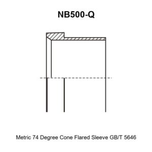
Nut and sleeve are ordered separately. The tee is supplied as the body only. Use nut NB200 with sleeve NB500 for metric tube, and nut NB200 with sleeve NB300 for inch tube, one set for each of the three legs.
3. How to Read an AJ Part Number
An AJ part number has two elements: the series prefix and one, two or three size codes. This series carries no sealing or geometry suffix, because the tee has three male cone ends and no other connection type.
The prefix AJ identifies the family: a JIC male 74° cone tee in the SAE J514 sizes, and the only all-male tee in the AJ adapter range. A different prefix identifies a different geometry, such as the AJ6JJ bulkhead branch tee, the CJ run tee, the BJ branch tee or the 1J straight stud.
A single size code means all three legs carry that thread. Three size codes are read in the order of the printed columns: the first is E (first run end), the second is F (the branch), and the third is G (second run end).
Worked example: AJ-04-06-04.
AJ– a JIC male 74° cone tee.04– the first run end, E, is the 7/16″x20 size.06– the branch end, F, is the 9/16″x18 size.04– the second run end, G, is the 7/16″x20 size.- From the table: A is 26.6 mm, B is 26.9 mm, C is 26.6 mm and S1 is 14 mm.
A buyer ordering AJ-04-06-04 therefore receives a tee with a larger branch on a smaller run, the usual way to feed an auxiliary line from a main line. The two run legs take 7/16″x20 nut and sleeve sets and the branch takes a 9/16″x18 set.
A reducing tee always has a smaller thread on the branch leg, and its B value is shorter than A and C for that reason.
4. Installation and Fitment
A 74° cone joint is started by hand and then tightened to seat the cone. HENGHUA does not print a single torque figure for the series, because the correct tightening depends on the nut and sleeve fitted, the tube material and the wall thickness. Confirm the figure with HENGHUA engineering per order, or follow the recommendation of the nut supplier. Never use a pipe extension or an impact tool on a cone joint.
Cone seat handling: keep all three cones and their mating seats clean and free of nicks. Wipe and inspect each cone under good light, and replace the tee if a cone shows galling or a flattened face.
Thread preparation: the threads of this joint are not the sealing element, so do not wrap them with thread tape and do not use sealant as a leak cure. A light oil on the threads lets the nuts run up smoothly.
Alignment: bring each tube squarely to its leg before starting the nut, because a tube pulled sideways into a cone loads the seat on one side and weeps at first pressure.
Contamination control: cap the open legs before storage and before the line returns to service, because debris that reaches a cone scores the face and produces a seep that tightening cannot remove.
Reuse policy: the body can be reused while all three cones are undamaged. The nut and sleeve are the wear items, and the tube assembly is replaced whenever a cone is damaged or a sleeve has been compressed on another tube.
Common fitment errors and their symptoms:
- Mixing a 37° flare with a 74° cone seat. Symptom: the nut runs up but the joint weeps at first pressure, and the two seat angles are visibly different.
- Fitting the wrong dash size on one leg of this hydraulic fitting adapter. Symptom: two joints seal and the third weeps, or the nut on that leg bottoms without touching the cone.
- Reusing a sleeve already compressed on another tube. Symptom: the tube pulls back from the cone and the joint leaks under vibration.
- Tightening all three nuts without checking the first two. Symptom: one cone is loaded off-centre and seeps even after re-tightening.
Six-step assembly
- Confirm the part number and check that E, F and G match the three tube assemblies.
- Inspect all three cones and the mating seats for nicks, corrosion and overtightening marks.
- Clean the cones and threads with a lint-free cloth and a compatible cleaning fluid.
- Fit the nut and sleeve to each tube, then bring each tube square to its leg by hand.
- Run each nut up by hand until it is snug, then tighten in stages to the recommended figure.
- Pressurise the circuit, check all three joints for weeping, and re-check tightness after the first thermal cycle.
5. Applications and Industries
Application tags for this series: hydraulic systems, water jetting, oil and gas, industrial equipment, construction machinery, agriculture, marine, material handling. A hydraulic fitting adapter of this kind is specified by its three thread sizes rather than by industry, so one tee serves several sectors.
Manifold and block take-off. A machine that has to feed an auxiliary function from a main line uses a JIC adapter tee at the take-off point. The run continues to the original load and the branch feeds the new one, and a reducing row such as AJ-08-06-08 gives the auxiliary line its own smaller size.
Test benches and instrumentation lines. Test rigs tee into a pressure line to read it, using the run for the main flow and the branch for the gauge line. Because every leg seals metal-to-metal, the tee can be removed and refitted between tests.
Repair and replacement. When a tube assembly or a tee is damaged, the tee is replaced with another of the same size codes rather than rebuilt. The printed range covers the common sizes, so a replacement comes from stock.
6. Replacement and Cross-Reference Guide
Cross-reference for this JIC adapter series is organised by standard and sealing method, never by brand. Two tee adapters interchange only if the standard, the three thread sizes, the leg arrangement and the seal type all match.
The AJ adapter is a SAE J514 JIC 74° cone tee with three male stud ends. It does not interchange with a run tee adapter or a branch tee adapter whose legs carry a female seat or another seal type, even where the threads match, because the tube assembly has to suit the connection on the leg. It does not interchange with a JIC 37° flare tee, because a 37° flare seals on the conical flare face while a 74° cone seals on the wide cone face, nor with an ORFS tee under SAE J1453, which seals a flat face against an O-ring, nor with an NPT tee, which seals on the thread flanks under ANSI/ASME B1.20.1.
To identify the correct replacement, measure three things.
- Threads on all three legs. Measure the outside diameter and count the threads per inch on each leg, and record which leg is the run and which is the branch.
- Seat angle. Use a seat angle gauge or a straight edge against each cone. A 74° cone is wide and shallow and a 37° flare is narrow and steeper, so the two will not mate regardless of thread match.
- Leg arrangement and lengths. Compare the A, B and C values of the part in hand with the printed row, because a tee whose branch height differs from the row you need may not clear the surrounding pipework.
Record the three measurements with the part number, and HENGHUA can match the replacement to the series and size code from the printed table in section 2.5. Where the line has to pass through a panel, order the AJ6JJ bulkhead branch tee instead.
7. Ordering, Packaging and Delivery
To order, give the following information:
- Series code:
AJ. - Full part number, for example AJ-08-06-08, taken from table 2.5.
- The three thread sizes, read from the E, F and G columns, and the leg each one belongs to.
- Nut and sleeve requirement for each leg, including the tube standard: nut NB200 with sleeve NB500 for metric tube, or nut NB200 with sleeve NB300 for inch tube. These are ordered separately from the tee.
- Seal material for the elastomer-sealed components in the circuit: NBR, FKM or EPDM.
- Body material and plating: carbon steel with trivalent chromium zinc plating, zinc-nickel plating, or 304 or 316 stainless steel.
- Quantity, destination and packing format.
Packaging formats: bulk cartons for line-side consumption, small boxes for distributor shelves and labelled bags for service kits, each labelled with the part number, the thread sizes and the quantity.
Sample orders: validation samples and first-article parts are available for OEM programmes, including drawing-based manufacture of specials where the printed table does not cover the required combination.
Lead time is confirmed per order, because it depends on the sizes, the material, the plating and the quantity. Send the requirement with the quantity and the required date, and HENGHUA confirms the schedule with the quotation. As a hydraulic adapter manufacturer and hydraulic adapter supplier, HENGHUA can quote the tee, the nut and the sleeve as one matched kit for each leg.
8. FAQ
What is the difference between JIC 37° flare and ORFS, and which should I use?
A JIC 37° flare joint seals metal-to-metal on a 37° conical flare face under SAE J514, and an ORFS joint seals a flat face against an elastomeric O-ring under SAE J1453. The AJ series is on the 74° cone side of SAE J514, which is a different seat again from the 37° flare, so choose the family that matches the seats already fitted to the equipment.
Can NPT and BSPT be interchanged?
No. NPT is a 60° taper pipe thread under ANSI/ASME B1.20.1 and BSPT is a 55° taper pipe thread under ISO 7-1, so the thread form, angle and pitch differ and the two will not seal even where a size starts by hand. The AJ tee is a straight-thread JIC part, so a tapered pipe thread is not involved on any leg. Where a pipe port has to be joined to a 74° cone line, order a cross standard adapter rather than forcing a thread.
How do I identify the correct AJ adapter size?
Measure the thread outside diameter and the pitch on each of the three mating tube assemblies, then read across the E, F and G columns of table 2.5 for that combination of three threads. When all three match a printed row, that row is the correct part number. Confirm which leg is the run and which is the branch before ordering, because a reducing tee is not symmetrical.
What seal material should I select for my fluid and temperature?
The 74° cone joints of this tee are metal-to-metal, so no seal material is needed for the tee itself. Select the compound for the elastomer-sealed parts of the same circuit: NBR for general mineral hydraulic oil in the range of approximately -30°C to +100°C, FKM (Viton-type) up to approximately +200°C or where the fluid attacks NBR, and EPDM for water and water-based fluids in the range of approximately -40°C to +120°C.
How is the working pressure of this tee determined?
Working pressure is not fixed by the series code. It is governed by the thread size, the wall thickness of the tee and of the tubes it joins, the sealing method and the material selected. Working pressure for these sizes is confirmed per order by HENGHUA engineering, against the intended circuit.
What is the minimum order quantity and can I get samples?
Minimum order quantity depends on the size codes, the material and the plating, so it is confirmed with the quotation rather than published as one series figure. Samples and validation parts are available for OEM and distributor evaluation, including specials made to a drawing.
How does this tee differ from the CJ run tee and the BJ branch tee?
All three are JIC 74° cone tees in this catalogue, and they differ in the leg arrangement and in the connection on each leg. The AJ adapter has a male cone stud end on all three legs, with the two run legs printed as E and G and the branch printed as F. The CJ series is a run tee adapter and the BJ series is a branch tee adapter, where the branch is the leg that the printed table dimensions in its own column. Check the drawing for which leg is the run before ordering any of the three.
Send your requirement to HENGHUA
Send the part number, the three thread sizes and their legs, the nut and sleeve requirement, the material and plating, and the quantity. HENGHUA confirms the match to the printed table, the seal options and the delivery schedule, and quotes the AJ adapter that fits your circuit.
Related series in the same family: the AJ6JJ adapter (branch tee) and the CJ adapter (run tee). Browse the full Hydraulic Adapters range for the complete SAE J514 JIC, NPT, ORFS and ISO 6162 flange families.

 English
  Spanish
  Portuguese
  French
  German
  Arabic