
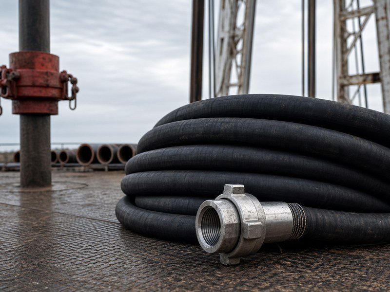
An oilfield hose is a flexible, wire-reinforced line built to carry drilling fluid, cement, fracturing fluid, or well-control fluid under pressure. The working pressure depends on the duty: a rotary drilling or vibrator hose is specified from about 4,000 psi to 7,500 psi (Grade C to Grade E), a fracturing hose commonly works at 10,000–15,000 psi at a Fig 1502 connection, a BOP control hose runs at 2,500–5,000 psi, and an oil suction and discharge line at the low end of the same catalogue is a 150 psi (10 bar) hose.
Getting the right one comes down to four decisions: the service the hose performs, the pressure and temperature it must hold, the bore and length the system needs, and the end connections and certification the project requires. This guide works through the high-pressure families used in petroleum and oilfield service — rotary drilling and vibrator hose, choke and kill hose, fracturing hose, cementing hose, and BOP control hose — and then covers how ratings are read, which standards govern them, how the fittings and unions are chosen, how suction and vacuum duty differs from pressure duty, how to compare oilfield suppliers on the basis of scope, and how to inspect and retire an assembly.
1. What Is an Oilfield Hose?
An oilfield hose is the flexible high-pressure connection that lets a rig, a well-service unit, or a well-control system move fluid between components that rigid pipe cannot join. A drilling rig is the clearest example: the swivel or top drive travels the full height of the derrick, the mud pumps pulse with every stroke, and the drill floor moves under load, so the line from the standpipe to the swivel has to follow that movement while holding several thousand psi of abrasive, solids-laden mud.
That combination — high pressure, continuous movement, and abrasive media — is what separates this family from industrial hose of the same bore. The reinforcement is heavier, the couplings are larger and usually built into or crimped onto the hose, and both the design and the testing are defined by oilfield standards rather than general industrial practice.
Construction: Why These Hoses Are Built in Layers
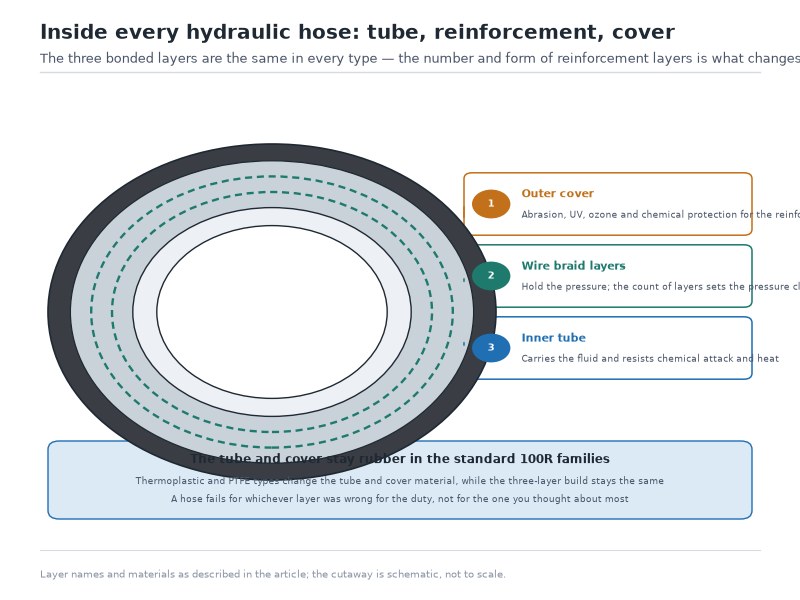
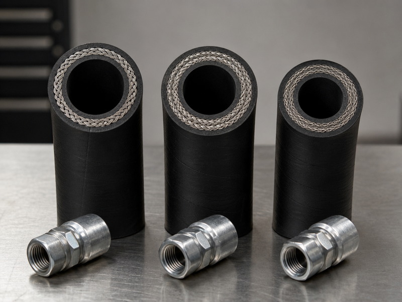
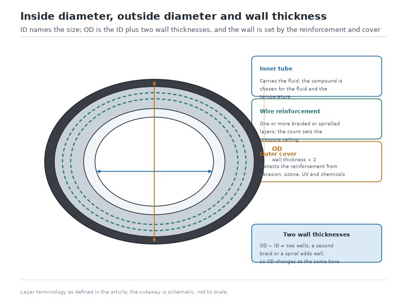
A high-pressure oilfield assembly is four layers — tube, spiral wire reinforcement, cover and end connection — and the reinforcement package, not the wall thickness, sets the pressure class.
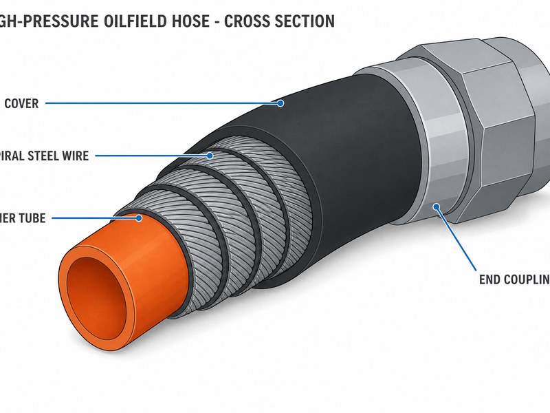
Figure 1. Wire-reinforced construction: the number of spiral steel layers sets the pressure class, while the cover and tube are chosen for the fluid and the environment.
Table 1. Construction of a high-pressure oilfield assembly, layer by layer. The cutaway above shows the layers; the table gives the material and the function of each.
| Layer | Typical material | Function |
|---|---|---|
| Inner tube | Nitrile (NBR) or modified nitrile | Carries the fluid; resists oil, acid, and abrasion from solids |
| Reinforcement | Two to eight layers of high-tensile spiral steel wire; some designs combine wire with textile plies | Carries working pressure and pressure surges; sets flexibility and minimum bend radius |
| Cover | Neoprene or oil-, ozone-, and weather-resistant rubber, sometimes with stainless armor | Protects the reinforcement from abrasion, UV, weather, and impact |
| End connection | Built-in or crimped coupling: union, flange, or hub | Seals the assembly and transfers the pressure load to the mating equipment |
Pressure capability comes from the reinforcement package, not from wall thickness alone. More wire layers and higher-strength wire raise the working pressure, and they also raise the weight and stiffness of the assembly. Bore sizes of 2 in to 4 in dominate drilling and well-service duty, while well-control lines run 2 in to 5 in.
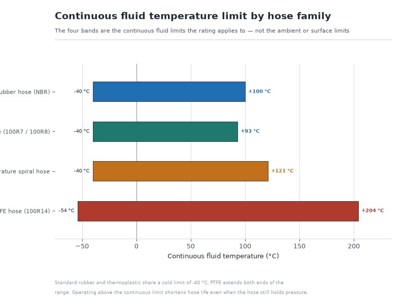
Standard compounds are quoted for roughly −20 °C to +121 °C (−4 °F to +250 °F); anything outside that temperature range is a conversation with the manufacturer, not a catalogue choice.
2. Which Types of Petroleum and Oilfield Hose Are Built for High Pressure?
The petroleum and oilfield family splits into six high-pressure types — rotary drilling, vibrator, choke and kill, fracturing, cementing, and BOP control hose — plus two low-pressure types that share the name but not the pressure class: oil suction and discharge hose, and tank truck hose. Buying the wrong family is the most expensive mistake in this category.
Table 2. Comparing the high-pressure families used in oilfield and petroleum service. Working pressures are API 7K grades where applicable (Grade C 4,000 psi, Grade D 5,000 psi, Grade E 7,500 psi); confirm the grade on the mill certificate. Above Grade E the pressure class comes from the project specification, not from the 7K grade ladder.
| Type | Where it works | Typical working pressure | Governing standard | Common bore |
|---|---|---|---|---|
| Rotary drilling hose (kelly hose) | Standpipe to swivel or top drive on a rig | 4,000–7,500 psi (Grade C–E: 4,000 / 5,000 / 7,500 psi) | API Spec 7K | 2–4 in |
| Vibrator hose | Mud pump discharge to standpipe | 4,000–7,500 psi (Grade C–E: 4,000 / 5,000 / 7,500 psi) | API Spec 7K | 2–4 in |
| Choke and kill hose | BOP stack to choke and kill manifold | 5,000 / 10,000 / 15,000 psi | API Spec 16C (FSL, per current edition) | 2–5 in |
| Fracturing hose (frac hose) | Frac pump to manifold or wellhead during stimulation | 10,000–15,000 psi | Project specification (API 7K-type construction where the project specifies it) | 2–4 in |
| Cementing hose | Cementing unit to wellhead or cementing head | 5,000 psi class and above | API Spec 7K | 2–4 in |
| BOP control hose | Hydraulic control of blowout preventers | 2,500–5,000 psi | API Spec 16D | 1/2–2 in |
Table 2 is a starting point, not a purchase specification. In practice, the family fixes the standard and the qualification evidence, while the actual assembly — bore, length, pressure class, ends, and documents — is defined by the application. If you need to compare families across the wider oil hose range, our oil hose application and selection guide sets out the same logic for transfer, hydraulic, and suction duty.
API 7K and API 16C: Where the Boundary Sits
Two standards cover most high-pressure oilfield assemblies, and the boundary between them is the service the assembly performs rather than the pressure it happens to see.
Table 3. API 7K versus API 16C: which standard governs which assembly
| Question | API Spec 7K | API Spec 16C |
|---|---|---|
| Scope of the specification | Drilling and well servicing equipment | Choke and kill equipment |
| Assemblies it governs | Rotary drilling (kelly) hose, vibrator hose, cementing hose, most well-service lines | The flexible choke and kill line on the well-control stack and manifold |
| Fracturing hose at 10,000–15,000 psi | Not covered by the 7K grade ladder (Grades C / D / E stop at 7,500 psi) — the project specifies an API 7K-type construction | Not governed — API 16C applies to the choke and kill line only |
| Pressure basis | Grade-based working pressure — Grade C 4,000 psi, Grade D 5,000 psi, Grade E 7,500 psi | Working pressure class of 5,000 / 10,000 / 15,000 psi with a flexible specification level, FSL 0 to FSL 3 |
| How the line is used | Works continuously on every circulating, cementing or well-service job | Held as a safety component that must perform during a well-control event |
| What the paperwork emphasises | Grade, bore, working pressure and the assembly test record | Flexible specification level, fire performance and the well-control document set |
The practical rule is to order to the standard of the equipment the assembly connects to. A 15,000 psi rotary-style line does not become a choke and kill line because the numbers match, and an API 16C line is not a general mud line because it fits the same union.
Not Every Hose on a Location Is High Pressure
Two families share the petroleum name but sit in a completely different pressure class. An oil suction and discharge (OS&D) hose is rated for vacuum and discharge service around the 150 psi (10 bar) class, and a tank truck or transfer hose is built to the same low-pressure order. They move fuel, not mud or frac fluid, and they are chosen for flow, flexibility, and static control rather than for pressure containment.
Our oil suction and discharge hose guide covers that selection procedure. The practical warning is commercial: a quotation that does not name the standard and the pressure class is not a quotation for a defined product, and a “high pressure hose” price that undercuts every other offer usually means the scope is missing reinforcement layers, end connections, or test records.
3. How Do Working Pressure, Test Pressure, and Burst Pressure Differ on a High-Pressure Hose?
Working pressure is the limit you operate at, test pressure is a quality check, and burst pressure is a design figure you never use as an operating limit — confusing the three is how projects end up unsafe or over-specified. Working pressure is the pressure the assembly may be used at continuously, at the rated temperature. Test (proof) pressure is a quality check applied before shipment or, in controlled conditions, in the field. Burst or design-verification pressure is the pressure at which the assembly is expected to fail — a design figure, never an operating limit.
Table 4. Pressure terms on a high-pressure oilfield assembly
| Term | What it means | Typical relationship |
|---|---|---|
| Maximum working pressure (MWP) | The rated limit for continuous service at the stated temperature | 100% — the number you design to |
| Factory proof / hydrostatic test | Acceptance test performed on the finished assembly before shipment | Commonly 1.5 × working pressure, held for a defined period (15 minutes is a typical factory hold for drilling hose) |
| Field pressure test | Periodic fitness-for-service test on a hose already in use | Public API RP 7L guidance for rotary hose caps this at 1.25 × MWP, with the hold not exceeding 10 minutes |
| Burst / design verification | The pressure at which the reinforcement is expected to fail | API 7K design practice uses a minimum burst ratio around 2.5 × working pressure |
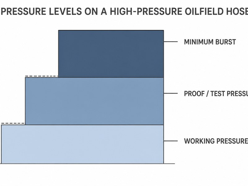
Figure 2. Reading the pressure ladder: working pressure is the operating limit, proof testing sits at about 1.5 times working pressure, field testing is capped at 1.25 times working pressure, and the minimum burst ratio for API 7K hose is about 2.5 times working pressure.
Two practical consequences follow. First, surge is real: mud pumps pulse with every stroke, and closing a valve on a flowing frac line converts velocity into a pressure spike, so the pressure class has to cover the transient, not just the gauge reading. Second, a higher class is not automatically better — up to a point, extra wire layers buy pressure at the cost of flexibility, weight, and handling hours on the rig floor. Our oil hose working pressure vs burst pressure guide sets out the same distinction for general oil hose.
4. How Do You Specify an Oilfield Hose? Seven Decisions That Define the Assembly
Those four groups map onto seven specification decisions: duty; pressure; bore; temperature and fluid; length and movement; ends; and testing and documents. A one-line request such as “4-inch hose, 5,000 psi, 20 meters” cannot be quoted correctly, because the supplier still has to guess the service, temperature, movement, ends, and documents. Seven decisions close that gap, and each one changes what gets manufactured.
Step 1: Define the duty, not just the fluid
The duty fixes the product family before any dimension is chosen. A kelly hose that runs standpipe-to-swivel has to survive constant vertical travel and bends over sheaves, while a vibrator hose sits close to the pump and absorbs pulsation, and a choke and kill hose sits on a well-control system that may never flow in normal operation but must work when it does. Same pressure class, three different fatigue and handling profiles.
Step 2: Set the pressure class from the real maximum, including surge
Start from the normal working pressure, then add the maximum expected operating pressure and the surge or pulsation the line will actually see. Frac work is the clearest case: a 15,000 psi frac hose is standard for high-rate stimulation, but the job only needs that class when the treating pressure reaches it — over-specifying every line on a spread adds weight and cost without adding safety. State the required working pressure and let the approved design define test and burst values.
Step 3: Size the bore from flow, not habit
Bore sets flow area, and flow area sets velocity. Annular velocity is volumetric flow divided by flow area: v = Q ÷ A, with A = π d² / 4 — write the required flow and the acceptable velocity first, then round to the nearest standard bore, because area scales with the square of diameter, doubling the bore roughly quadruples the flow area at the same velocity — which is why a 3 in line can carry far more than twice the volume of a 2 in line at the same speed. High velocity is not free on the drilling side: it increases erosion of the tube and pressure loss.
Step 4: Fix the temperature and fluid compatibility
The tube compound has to match the media and the temperature. Oil-based mud, acidizing fluids, and cement slurries attack different compounds in different ways, and low ambient temperature affects flexibility at start-up. If hydrogen sulphide is present, say so explicitly: sour service changes both tube material and coupling material requirements, and it is normally referred to NACE MR0175 / ISO 15156. This is a separate clause in the enquiry, not an assumption the supplier can make.
Step 5: State length, bend radius, and movement
Length is only meaningful with a datum. End-to-end, seal-face-to-seal-face, and centreline dimensions differ by the depth of the couplings, so put the datum and the tolerance on the drawing. For moving service, confirm the routing against the minimum bend radius and the travel — buying the shortest hose that reaches is a common cause of premature failure at the coupling.
Step 6: Choose the end connections and orientation
Ends are the largest single reason two quotes for the same hose differ, so specify End A and End B separately with size, figure or pressure class, standard, face or thread, and material. If orientation matters, add a clocking drawing. Step 7 and the fittings section below cover the practical choices.
Step 7: Define testing, marking, and documentation before the order
Decide what is inspected, what is tested, who witnesses it, and which records ship with the assembly. That package is far cheaper to agree at enquiry stage than to reconstruct after production, and it is the difference between a hose you can audit and a hose you can only hope about. Send the five defining parameters — the duty, the pressure class, the bore, the temperature and fluid, and the end connections — and our engineers will confirm the construction, the standard and the document package before you commit to a design. Contact HENGHUA for a quote and free samples.
5. Which End Connections Suit High-Pressure Oilfield Hose?
High-pressure oilfield connections come in three families — the hammer union, the flange, and the hub — and the union is the one that defines the sector. A hammer union is a three-piece threaded coupling with a coarse square thread and a soft seal ring, tightened with a hammer rather than tools; it connects and disconnects in seconds, which is exactly what a rig or frac spread needs.
Table 5. Union figure numbers and their cold working pressure (CWP)
| Figure | Cold working pressure | Typical service |
|---|---|---|
| Fig 100 / Fig 200 | 1,000 / 2,000 psi | Low-pressure utility, water, and air lines on a location |
| Fig 400 (402) | 4,000 psi | Medium-pressure manifolds and test lines |
| Fig 602 | 6,000 psi | Mud, cement, and treating lines; replaceable lip-type seal |
| Fig 1002 | 10,000 psi | Cementing, acidizing, and well-service lines |
| Fig 1502 | 15,000 psi | Fracturing, acidizing, choke and kill lines, well service — the de facto oilfield standard |
| Fig 2002 / 2202 | 20,000 / 22,000 psi | Highest-pressure frac and well-control service where specified |
Match the figure to the pressure class rather than to what is on the shelf. Do not confuse the 22,500 psi proof test on a Fig 1502 with the 22,000 psi cold working pressure of a Fig 2202 union: one is a 1.5x factory proof test, the other a class rating for a different figure. Fig 1502 carries a 15,000 psi cold working pressure and is commonly offered with a factory proof test at about 1.5 times its cold working pressure (22,500 psi) — see the test chart for the value that applies to your order.
Seal material matters as much as the figure: Buna-N seals suit oil and water service, while H₂S or aggressive chemical duty calls for a different elastomer, and the union body itself may need a sour-service material grade.
How to Read a Union Figure Number
A union figure number is not an arbitrary label. Drop the last digit and multiply the remainder by 100 psi, and the result is the cold working pressure class. The rule reads straight off Table 5: Fig 602 is 6 × 100 = 6,000 psi, Fig 1002 is 100 × 100 = 10,000 psi, and Fig 1502 is 150 × 100 = 15,000 psi. That arithmetic is the practical reason Fig 1502 became the default fracturing, acidizing and well-control connection rather than a proprietary choice. Check the class against the cold working pressure published for the specific union you are buying, because machining, seal type and material grade all sit on top of the figure number. The rule gives the class, never the test pressure, and a pressure figure on a connection is never an operating limit.
Which Union Figure Do You Need at 6,000, 10,000, 15,000 and 20,000 psi?
Table 6. Union figure for each service pressure class
| Service pressure class | Union figure | Where it is used |
|---|---|---|
| 6,000 psi | Fig 602 | Low-pressure well-service and cementing lines |
| 10,000 psi | Fig 1002 | Medium-pressure well-service and stimulation lines |
| 15,000 psi | Fig 1502 | Fracturing, acidizing and well-control connections |
| 20,000 psi / 22,000 psi | Fig 2002 / Fig 2202 | High-pressure stimulation and well-control service |
A figure is chosen for the class of the line, and the seal compound for the fluid — a higher figure is not a substitute for a correctly rated hose.
Send the figure number, the pressure class and the seal material you need, and our engineers will confirm the union and the hose class that match. Contact HENGHUA for a quote and free samples.
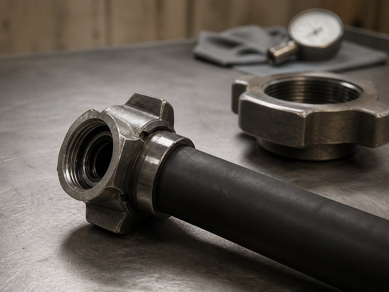
Figure 3. Fig 1502 hammer unions on a 15,000 psi assembly: coarse threads and a soft seal allow a make-up in seconds with a hammer.
Not every high-pressure line is made up with a hammer. Well-control and offshore work often specifies an API 6A flange or a clamped hub connection, and large-bore fracturing lines may use flanged or hub ends on the pump side. Whatever the type, two rules hold. First, specify whether you want integral (built-in) or crimped ends, since the two designs have different service limits, lead times, and validation routes. Second, build the assembly with the exact ends the ports need: every adapter adds joints, length, weight, and a potential leak path. If you also work with hydraulic systems, the same naming logic for threaded ends is covered in our hydraulic fittings types guide.
6. What Standards and Documentation Should Come With a High-Pressure Oilfield Assembly?
Standards are the shorthand that tells you a hose was designed, manufactured, and tested for a defined service. Four references cover most of the world’s high-pressure oilfield assemblies, and a serious enquiry names them rather than asking for “API hose”.
- API Spec 7K — the product specification for drilling and well servicing equipment, and the reference behind kelly and vibrator hose, cementing hose, and most well-service lines.
- API RP 7L — the recommended practice for inspection, maintenance, and repair of drilling equipment. Its published guidance on rotary hose field pressure testing (a cap of 1.25 × maximum working pressure and a hold of no more than 10 minutes) is the most useful public reference for a field test programme.
- API Spec 16C — the specification for choke and kill equipment, which includes the flexible choke and kill line used on a well-control system. Industry practice describes a flexible specification level, commonly written FSL 0 to FSL 3, and the higher the level the more demanding the design, material, and validation requirements — including fire testing, where the line is exposed to flame for a defined period and must show no leakage or loss of pressure.
- API Spec 16D — the specification for control systems for drilling well-control equipment, and the reference for BOP control hose. The published fire requirement is commonly stated as holding rated working pressure in a flame at 1,300 °F (700 °C) for 5 minutes — confirm the current edition figure on the certificate.
Sour service sits alongside these standards rather than inside them. If hydrogen sulphide is present, the tube, the coupling material, and the seal compound are all affected, and the requirement is normally referred to NACE MR0175 / ISO 15156. Offshore projects commonly add a classification society requirement — DNV, ABS, or CCS — with its own witness points and document set.
Certification language then has to be read carefully, because three phrases point to three different things (Table 7). An assembly is only as auditable as the paperwork that travels with it, which is why the document list should be agreed at enquiry stage:
Table 7. Certification phrases and what each one evidences
| Phrase | What it actually evidences |
|---|---|
| “API compliant” | A claim about the product, made by the supplier |
| “Manufactured under an API quality system” | The factory’s quality system, not the product |
| API Monogram | A licence to mark a specific product, within a defined scope |
Each phrase points to something different, so ask which one applies and ask to see its scope, because a high pressure hose certificate and a factory quality-system certificate are not the same document.
Table 8. Document package for a high-pressure oilfield assembly
| Document | What it establishes | When to insist on it |
|---|---|---|
| Certificate of conformance | That the assembly was supplied against the named standard and specification | Every order |
| Assembly hydrostatic test certificate with pressure chart | That the finished assembly held the specified pressure for the specified time | Every high-pressure assembly |
| Material certificates / mill certificates for coupling bodies and forgings | That the ends are the grade and heat treatment you specified | High-pressure ends, sour service, low-temperature service |
| Approved drawing with end connections and orientation | That length datum, clocking, and end details were built as agreed | Any assembly with a non-standard end or routing constraint |
| Inspection and test plan (ITP) with hold and witness points | Who inspects what, and when the customer or third party is involved | Project and offshore work |
| Traceability record tied to the assembly serial number | That the hose, its test, and its history can be traced through its life | Where an integrity programme or audit applies |
Every compliant assembly also carries a marking line on the cover with the manufacturer, standard, bore, working pressure, and a traceable identity. Read it on arrival and record it, because marking is what connects the physical hose to the certificate in your filing system. If you are building the document package for a project, send the requirement list to our engineering team and we will confirm it against the standard the assembly is built to.
7. What Drives the Cost of a High-Pressure Oilfield Hose?
There is no universal price per foot for a high-pressure oilfield assembly, and any quotation that leads with one is pricing an incomplete scope. A 3 in frac hose and a 3 in fuel transfer hose share a nominal bore and nothing else — different wire reinforcement, different couplings, different testing, different documents. Cost follows the scope, and the scope has seven visible drivers.
- Size and length. Larger bore means more tube compound, more wire, larger couplings, and heavier handling; long assemblies also change production, testing, and freight arrangements.
- Pressure class. Higher working pressure adds reinforcement layers, higher-strength wire, beefier end connections, and a more demanding qualification basis.
- Construction. Tube compound, cover compound, and any armor or external protection are separate line items, and each may be quoted or excluded by different suppliers.
- End connections. Frequently the largest single difference between two quotes — a Fig 1502 union, an API 6A flange, and a clamped hub involve very different material, machining, welding, and inspection work.
- Testing and inspection. Design qualification, production proof testing, and field fitness-for-service testing are three different activities. Third-party witness adds coordination and reporting on top.
- Documentation. A certificate of conformance is not a data book. Material certificates, NDE reports, calibration records, and indexed documentation carry real production cost.
- Quantity and schedule. Engineering, setup, tooling, and documentation are largely fixed per design, so identical assemblies in a batch spread that cost, while mixed designs and split deliveries carry it in full. Urgency is its own line item.
The practical way to control cost is not to shop for the lowest number but to normalize the scope. Build a comparison table with one row per requirement and mark each offer as included, excluded, optional, or not stated, then compare the totals. Underspecifying is unsafe; over-specifying is expensive — copying the most severe pressure, temperature, and documentation values from four different projects onto one enquiry pushes the order into a heavier, slower, and costlier design without improving the duty. Repeat approved sizes, ends, and document formats where the system allows it, and ask for spares to be priced as a separate line so the decision is visible.
8. How Long Does a High-Pressure Hose Last, and How Is It Inspected?
There is no defensible five-year rule for a high-pressure assembly. Service life depends on the duty, the fluid, the environment, the number of pressure cycles, and how the hose is handled, so the correct basis is condition plus the manufacturer’s stated limits and your own integrity programme. That is why inspection is a schedule, not an event:
- Verify identity first: assembly serial number, standard, working pressure, size, end connections, and last inspection or test. Quarantine anything that cannot be identified.
- Inspect the cover for cuts, gouges, blisters, bulges, soft spots, and abrasion exposing reinforcement.
- Check for kinks, crushing, twist, and flat spots, especially near the end connections.
- Inspect couplings for cracks, distortion, corrosion, seal leakage, and any movement between the hose body and the coupling.
- Confirm restraints and safety clamps — whip checks, hobbles, and slings — are fitted, undamaged, and correctly positioned.
- Check the routing: no twist, no axial pull, no bending tighter than the published minimum bend radius, and no contact with structures that can abrade the cover.
For rotary hose exposed to pressurized gas, the liner needs a different check, because gas can permeate the tube and collapse the liner when pressure is released. Public API RP 7L guidance describes full-length borescope examination for this service and treats bulges, blisters, punctures, or any liner breach as cause for rejection.
Field pressure testing, where it is required, must be treated as a controlled operation: trained personnel, an approved procedure, energy isolation, rated restraints, and calibrated instruments. On rotary hose, the public API RP 7L bound is 1.25 times the maximum working pressure, held for no more than 10 minutes. Prepare the hose straight where possible and without twist, bleed all air, use water where possible, and raise pressure at a controlled rate.
Those figures are guidance boundaries, not a universal test recipe, and they must not be copied onto an API 16C choke and kill line, which follows its own product test requirements. A passing hydrostatic test confirms pressure integrity at that moment; it does not prove remaining fatigue life, chemical compatibility, sour-service capability, or fire resistance.
Storage deserves its own rule. A flexible choke and kill line is not stock material to hold for years: industry practice is that long-term storage is not recommended, and warranties are typically counted from the dispatch date. Ordering early to build safety stock quietly consumes usable life, so supply planning has to follow the real drilling schedule.
If You Are Specifying a New Assembly
Give the five defining parameters and the document package, and the assembly can be quoted without a second round of questions: the duty, the governing standard, the working pressure including surge, the bore and length, and the ends at both sides. Add the temperature, the fluid including any H₂S, and the document set the project requires. Stated that way, the offer comes back as a defined high pressure hose assembly with the ends, the test record and the documents already inside it.
If You Are Putting a Hose Back Into Service
Check the identity marking first, then the cover and the liner, then the restraints and the routing. A hose that cannot be traced to its certificate, or that shows bulges, blisters, punctures or any liner breach, goes out of service regardless of its pressure rating.
If You Are Comparing Two Quotes
Compare scope line by line rather than on the headline price: the governing standard, the certification, the material certificates, the test records, the ends, the delivery split and the urgency premium. Two quotes for the same nominal hose can differ only in what is excluded.
9. Frequently Asked Questions
What is an oilfield hose used for?
An oilfield hose moves fluid under high pressure between equipment that cannot be joined by rigid pipe: drilling mud from the pumps to the standpipe and up to the swivel or top drive, cement from a cementing unit to the wellhead, fracturing fluid from the pumps to the manifold and wellhead, and well-control fluid between the BOP stack and the choke and kill manifold. It is also used for hydraulic control of blowout preventers. The common factor is high working pressure combined with movement, vibration, or repeated make-up and break-out.
What is the difference between API 7K and API 16C hose?
API 7K is the product specification for drilling and well servicing equipment, and it governs rotary drilling hose, vibrator hose, cementing hose, and most well-service lines. API 16C governs choke and kill equipment, including the flexible choke and kill hose used in well-control systems, and industry practice describes a flexible specification level, commonly written FSL 0 to FSL 3, with increasingly demanding requirements as the level rises. The practical difference is service: API 7K hose works every day, while an API 16C line is a safety component designed to perform during a well-control event.
What working pressure does a rotary drilling hose have?
Mainstream rotary drilling hose is supplied in grade C at 4,000 psi, grade D at 5,000 psi, and grade E at 7,500 psi, with higher ratings available for high-pressure systems. Bore sizes commonly run 2 in to 4 in, and standard compounds are rated for roughly −20 °C to +121 °C. Set the requirement from your maximum pump discharge pressure including surge, and confirm the rating on the certificate rather than assuming every 5,000 psi hose is built to the same design.
What is a hammer union, and which figure do I need for 15,000 psi?
A hammer union is a three-piece threaded coupling with a coarse square thread and a soft seal ring, made up with a hammer rather than tools. The figure number states its cold working pressure class: Fig 602 is 6,000 psi, Fig 1002 is 10,000 psi, and Fig 1502 is 15,000 psi, which is why Fig 1502 dominates fracturing, acidizing, and choke and kill service. Match the figure to the pressure class and the seal compound to the fluid.
Can a standard high pressure hose be used for drilling mud?
Drilling mud service needs a purpose-built hose. A general purpose high pressure hose is built for a clean hydraulic fluid, and drilling mud carries abrasive solids under continuous pump pulsation, which erodes and fatigues a tube and reinforcement package designed for a different duty. Rotary, vibrator, and cement hose under API 7K use heavier spiral wire reinforcement and abrasion-resistant tube compounds for that duty. Using an unqualified line on a mud or cement service trades a small saving on the hose for a risk to people and equipment.
How much does a frac hose cost?
A fracturing hose has no meaningful price per foot until the assembly is defined, because size, pressure class, length, end connections, testing, documentation, and quantity all move the number. A 15,000 psi assembly with Fig 1502 ends, a pressure test certificate, and a defined document package is a different purchase from a hose body alone. Define the assembly, send the same specification to every qualified supplier, and compare the included scope rather than the headline figure.
What does sour service change on an oilfield hose?
Sour service — a fluid carrying hydrogen sulphide — changes the material requirements before it changes the pressure class. The hose body, the end connection and any wetted metal have to be selected for sour service to NACE MR0175 / ISO 15156, and the seal compound has to be compatible with the fluid rather than simply oil-resistant. Ask for the material certificate with the assembly, because the pressure rating on its own does not evidence sour-service suitability.
Can a high-pressure hose be pressure-tested in the field?
A high-pressure assembly can be field-tested only as a controlled operation: rated restraints, energy isolation, calibrated instruments and an approved written procedure. On rotary hose the public API RP 7L bound is 1.25 × MWP held for no longer than 10 minutes, and that bound must not be copied onto an API 16C choke and kill line, which is governed by its own well-control requirements. Field testing verifies the assembly that was built; it is not a substitute for the factory proof test.
Which union figure should I order for my pressure class?
Choose the figure for the class of the line, not the highest number available. A 6,000 psi line takes a Fig 602, a 10,000 psi line a Fig 1002, a 15,000 psi line a Fig 1502, and 20,000 psi and 22,000 psi lines take a Fig 2002 or Fig 2202. The seal compound is then chosen for the fluid. A higher figure is not a substitute for a correctly rated hose, and the rule gives the class, never the test pressure. The same class rule applies to a rotary drilling hose, a frac hose and a choke and kill hose.
10. Final Verdict
Assemblies for high-pressure petroleum and oilfield service are a specification purchase, and the sequence never changes: fix the duty and the standard first, set the pressure class from the real maximum including surge, size the bore from flow, confirm temperature and fluid compatibility including sour service, choose the ends and orientation, and agree the test and document package before production. An assembly that is properly specified is a durable, repairable, low-cost component of a drilling or well-service spread; one that is specified from a catalogue headline is a liability waiting for the wrong moment.
If you are sourcing assemblies for a rig, a well-service fleet, or an OEM programme, send HENGHUA your service data, connection details, and document requirements. We review the application against the correct standard, confirm the construction and pressure class, and quote line by line — hose body, ends, testing, documentation, packing, and lead time — so you can compare our offer with any other supplier on the same basis and order the right oilfield hose with confidence. Talk to our assembly engineers about your design.
 English
  Spanish
  Portuguese
  French
  German
  Arabic
  Russian