
Here is the short answer: how to measure hydraulic hose comes down to three separate numbers — overall length, inside diameter (ID), and the end connection. Length is measured end-to-end between the extreme ends of the two couplings, or from sealing face to sealing face when the ends are O-ring face seal, and always through the centre line of an elbow. ID is read at the *cut end* of the hose with calipers or a sizing dowel, never from the outside. The end connection is identified by thread outside diameter, thread pitch and seat type — never by the size of the hex nut.
Failed hose orders almost always trace back to one of those three numbers rather than to the hose body itself.
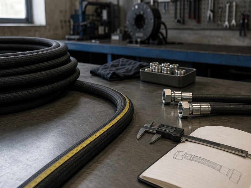
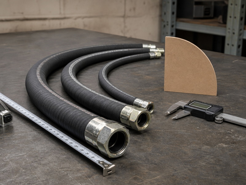
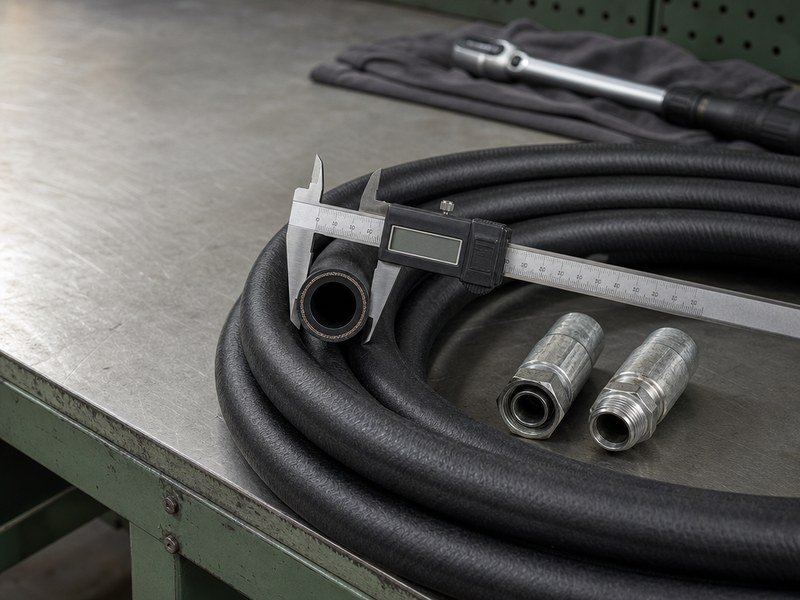
Cover image. A measuring station for a replacement hose: soft tape for length, digital calipers for the bore and the thread, and the crimped assemblies for comparison.
This guide follows the order a competent assembly shop takes them in: reading hydraulic hose length on a line that is still installed and on one that has already been cut, reading hydraulic hose ID accurately and converting it to dash size, recognising hydraulic hose fittings by measuring threads and seats across JIC, ORFS, O-ring boss, NPTF, BSPP and four-bolt flange ends, measuring elbow angles and bend radius, allowing for crimp growth and pressure-induced length change, and writing the result down in a form a supplier can quote from without a second phone call.
What Are the Three Dimensions You Measure on a Hydraulic Hose?
A hose assembly is defined by three independent measurements, and a supplier needs all three before a replacement can be built correctly. They are independent because two hoses with the same outside diameter can have different bores, and two hoses with the same bore can carry completely different end connections. Measuring one and assuming the others is the single most expensive shortcut in hose replacement work.
Each dimension controls a different failure mode. Length decides whether the assembly reaches both ports without being stretched, kinked or looped. Bore decides fluid velocity, pressure drop and heat build-up. The end connection decides whether the assembly can physically bolt up and seal at working pressure. A hose that is 20 mm too long will usually still work; a hose with the wrong seat type will not seal at all.
In practice, take the three measurements in this order:
- Length first, while the machine is still assembled and the routing is visible.
- ID second, from the cut end of the old hose or from the port it served.
- End connections last, because identifying a thread and seat type needs the old hose in hand.
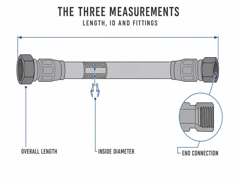
Figure 1. The three dimensions of a hydraulic hose assembly. Length is an overall figure that includes both couplings; ID is a bore measurement taken at the tube; the end connection is defined by thread size and seat type.
Table 1 – The three dimensions of a hydraulic hose assembly and what each one controls
| Dimension | Measured | Controls | If it is wrong |
|---|---|---|---|
| Length | Overall, end to end (or seat to seat for O-ring face seal) | Reach, routing, slack, bend radius | Stretched, kinked or abraded hose; short service life |
| Inside diameter (ID) | At the cut end of the tube | Flow velocity, pressure drop, heat | Overheating, sluggish actuation, internal erosion |
| End connection | Thread OD, thread pitch, seat type, elbow angle | Whether it bolts up and seals | Will not assemble, or leaks at pressure |
The reason length needs its own definition is that “length” is ambiguous once couplings are fitted. SAE J517, the hose-assembly standard, settles it: unless otherwise specified, assembly length is the overall length measured from the extreme end of one connector to the extreme end of the other — except for O-ring face seal connectors, which are measured from the sealing face. Where elbow connectors are used, the measurement runs to the centre line of the sealing surface of the elbow end.
Step 1: How to Measure Hydraulic Hose Length
Length is the measurement people get wrong most often, and the reason is almost never the tape measure — it is the definition. A hose measured with the old assembly still under pressure, still routed through a bend, or measured along its outer curve rather than its centre line will produce a number that is short by a predictable and repeatable margin. What follows is how to measure hydraulic hose length in the order that avoids that error.
Measure From Where, Exactly? The Sealing Face Rule
Start by deciding what the two reference points are, because they are not always the extreme outer ends of the couplings.
- Standard couplings (straight, elbow, flange): measure from the extreme end of one connector to the extreme end of the other.
- O-ring face seal (ORFS) ends: measure from sealing face to sealing face. The flat face of the fitting is the reference, not the nut. Pull the nut back to expose the seat before you measure.
- Elbow ends: measure to the centre line of the sealing surface, not to the outer edge of the elbow body. Measuring to the outer edge of a 90° elbow adds roughly half the elbow’s width to the assembly and produces a hose that is consistently long.
How to Measure a Hose That Is Still Installed
Measuring in place is the better method, because the installed routing already accounts for how the hose actually behaves on the machine.
- Depressurise and lock out the machine. A pressurised hose is longer than a relaxed one.
- Clean the area around both ports. Grease and grime hide the reference edges you need to read.
- Identify the reference points using the sealing face rule above and mark them with a paint pen.
- Run a soft tape along the centre line of the hose, following the installed path through every bend. Do not pull the tape tight across a bend — follow the curve.
- Read the tape at the second reference mark and record the number together with the port positions.
If the hose is hidden behind guarding or runs through a bulkhead, measure the distance between the two ports along the intended route instead, then add the fitting take-up for both ends.
Two safety rules apply every time a hydraulic circuit is opened. Isolate and lock out the machine first, because accumulators and raised implements hold pressure even with the pump off. Then look for a suspected leak with a sheet of cardboard rather than a hand: a pinhole jet can inject fluid through skin without pain at the moment of injury, and the resulting injection injury is a surgical emergency.
Measuring With the Machine Down: What You Can Confirm in Place
Table 6a. What can be confirmed with the hose still on the machine, and what cannot
| Measurement | Still on the machine | Hose off the machine |
|---|---|---|
| Bore (ID) | Shortlist only, from the coupling bore or the port bore | Confirm at a clean square cut |
| Length | Along the intended route between the two ports, with the hose relaxed | Centre-line measurement with the coupling take-up added |
| End connection | Read the port rather than the old fitting, because ports are replaced and retapped | Measure the thread and confirm the seat feature |
| Elbow orientation | Record it in place, before anything is removed | Not recoverable once the assembly is off |
How to Measure a Hose That Has Already Been Removed
An old hose that has been in service has already changed length. Rubber relaxes, reinforcement creeps and the assembly may have grown or shrunk by a small but meaningful amount over its life, so an old hose should be treated as a cross-check rather than the primary reference.
- Lay the hose flat on a bench and let it relax for a few minutes. Do not pull it straight under tension.
- Straighten it by hand only. Stretching the hose to make it lie flat adds length that you will then order by mistake.
- Measure along the centre line of the tube, not the outside curve of a bent hose and not the inside curve.
- Measure to the correct reference points for the seat type, as above.
- Compare against the installed routing measurement. If the two disagree, trust the installed measurement unless you have a reason not to.
Cut Length vs Overall Assembly Length: Allow for Crimp Growth
The length of hose you cut is not the length of the assembly you get. Crimping the couplings onto the tube pushes the hose body outward, and the finished assembly measures longer than the cut hose.
The size of that growth is not trivial. In an independent distributor bench test, a 1-1/4 in hose cut and assembled to a target overall length of exactly 26 in measured just under 26.5 in once -20 (1-1/4 in) male JIC and male NPT ends were crimped on — nearly half an inch of growth, roughly 1.9% of the assembly length — a figure that comes from public distributor bench data rather than from a length standard, so treat it as an indication of the size of the effect rather than as an allowable tolerance. On a short assembly with a tight routing envelope, that is the difference between a hose that fits and one that does not.
The practical rule is straightforward: specify the overall assembly length you need, and let the hose builder work back to the cut length. If you cut the tube yourself, cut it shorter than the target overall length by the coupling take-up for both ends, then verify after crimping and before dispatch.
How Much Extra Length Should You Allow?
A hydraulic hose changes length in service, and the two figures below are measured from different baselines. Against its relaxed length on the bench, a hose under working pressure can elongate by up to about 2 percent. Measured against the same hose when it is first pressurised, a hose that has taken a compression set under pressure can read up to about 4 percent shorter. Both figures move with pressure, construction and size, which is why a routing that works at zero pressure can fail at working pressure.
Allow for it by:
- Providing slack for the shortest condition. If the hose shortens by up to 4 percent against its first-pressurised length, a taut hose will pull on its couplings.
- Providing room for the longest condition. If it elongates by up to 2 percent against its relaxed bench length, an already tight bend will close further.
- Never using slack as a substitute for a bend. Extra length that hangs in a loop is more likely to abrade or snag than a correctly routed hose.
- Respecting the minimum bend radius at every point along the run, including the length change.
Table 2 – Standard length tolerances for hydraulic hose assemblies, by overall assembly length
| Overall assembly length | Tolerance |
|---|---|
| Up to 12 in (304.8 mm) | ±1/8 in |
| Over 12 in to 18 in (304.8–457.2 mm) | ±3/16 in |
| Over 18 in to 36 in (457.2–914.4 mm) | ±1/4 in |
| Over 36 in (914.4 mm) | ±1% of overall length |
These are the length tolerance bands published under the NAHAD distributor guidelines that most North American hose distributors quote against — public distributor guidance rather than a hose standard, which is why the band is quoted rather than derived. They matter for a practical reason: if you need an assembly to land inside a window narrower than the tolerance band, say so when you order, because a standard build cannot guarantee it.
Step 2: How to Measure Hydraulic Hose ID (Inner Diameter)
In how to measure hydraulic hose, the inner diameter is the measurement that decides how the hose performs, and it is the one that cannot be read from the outside of an assembly. Two hoses with identical outside diameter can have different bores, because a high-pressure hose carries more reinforcement layers inside the same cover. That is why a large hydraulic hose catalogue lists the same nominal bore across several constructions with different outside diameters.
Knowing how to measure hydraulic hose ID is therefore a question of knowing *where* to put the calipers, not how hard to squeeze them.
The rule to remember: ID is measured at the cut end of the hose tube, with the reinforcement exposed and no coupling in the way.
Method 1 — How Do You Read ID With Digital Calipers?
This is the most accurate method available on a bench and the one to use when the hose is already removed.
- Cut a clean, square section through the hose with a hose cut-off machine or a fine-tooth blade. A ragged cut distorts the bore.
- Open the caliper jaws into the bore and seat them on the widest internal diameter, not across an exposed wire end.
- Read at three points about 120° apart and average them. An oval bore from a hose that has been stored coiled is common.
- Take the reading a few millimetres back from the cut face, away from any swaging or wire flare.
Digital calipers in the common 0-150 mm size resolve to 0.01 mm, which is far finer than the hose manufacturing tolerance itself — the point is not the last digit, it is confirming which nominal bore you have.
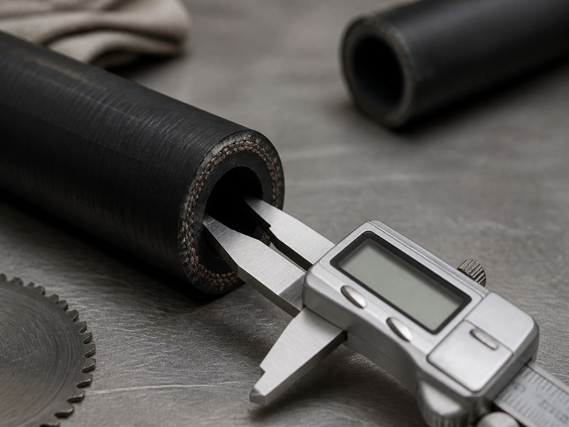
Figure 2. Measuring hydraulic hose ID at a clean square cut end. Read three points about 120° apart and average them, because a hose stored coiled will often read slightly oval.
Method 2 — Sizing Dowel and Pin Gauges
A sizing dowel is a stepped or cylindrical gauge machined to nominal bore sizes. You push it into the cut end; the largest step that enters without force is the bore size. Pin gauges work the same way and are common in job shops that already hold a set for machining work.
The advantage is speed and the absence of interpretation — there is no reading to misread and no ovality to average out. The limitation is that a sizing dowel confirms a nominal size rather than telling you the actual bore, so it will not reveal a hose that is at the edge of its tolerance band.
Method 3 — Hose ID Gauge and Dash-Size Kit
A bore gauge set is a set of stepped inserts or a tapered gauge marked directly in hydraulic hose dash size. For maintenance teams who deal in dash sizes rather than millimetres, this removes the conversion step entirely and is the fastest field method.
Why Measuring OD and Subtracting Wall Thickness Fails
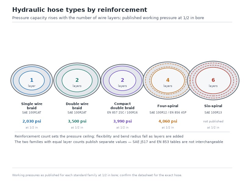
Measuring the outside diameter and subtracting an assumed wall thickness does not work, and it is a common source of wrong hose orders. The reason is that wall thickness is not a fixed number — it varies with the number of reinforcement layers, the wire or textile type, the cover compound and the pressure rating. A 1/2 inch (-8) bore hose has a nominal inside diameter of 12.7 mm, and its outside diameter runs from about 20.0 to 21.4 mm on a single-wire-braid line, about 22.5 to 23.0 mm on a double-wire-braid line and about 23.8 to 25.4 mm on a four-spiral high-pressure construction, with a heavy abrasion-resistant cover adding more again.
There is also no fixed arithmetic relationship between outside diameter and dash size, so any conversion table that maps OD directly to dash size is only valid for one specific hose construction. Use OD to identify a hose family in a catalogue, and use the bore to identify the hose.
Converting ID to Dash Size
Hydraulic hose dash size is simply the nominal inside diameter expressed in sixteenths of an inch. The number after the dash is the numerator; the denominator of 16 is understood. A -8 hose has a nominal bore of 8/16 in, which is 1/2 in.
The conversion is counted in sixteenths, not in inches. This trips people up constantly, because dash numbers are frequently mistaken for a metric or a sequential size code. The same figures are available as a printable reference in the hydraulic hose size chart.
Table 3 – Dash size to nominal inside diameter conversion for hydraulic hose
| Dash size | Nominal ID (fraction) | Nominal ID (in) | Nominal ID (mm) |
|---|---|---|---|
| -4 | 4/16 | 1/4 | 6.4 |
| -5 | 5/16 | 5/16 | 7.9 |
| -6 | 6/16 | 3/8 | 9.5 |
| -8 | 8/16 | 1/2 | 12.7 |
| -10 | 10/16 | 5/8 | 15.9 |
| -12 | 12/16 | 3/4 | 19.1 |
| -16 | 16/16 | 1 | 25.4 |
| -20 | 20/16 | 1-1/4 | 31.8 |
| -24 | 24/16 | 1-1/2 | 38.1 |
| -32 | 32/16 | 2 | 50.8 |
Two honest caveats on this table. First, dash sizes are nominal: the hose standards permit an ID tolerance, so a caliper reading on a -8 hose may sit a few tenths of a millimetre either side of 12.7 mm without the hose being out of specification. Second, dash size applies to inch-series hose. Metric hose is designated by its actual bore in millimetres, so an M12 line is not a dash size and should never be recorded as one.
Step 3: How to Measure Hydraulic Hose Fittings
Fittings are the hardest of the three measurements because four different properties have to be identified, and only the first one is a number. This is the stage of how to measure hydraulic hose where a caliper on its own is not enough — you need the standard as well, because the thread holds the connection together while the seat is what actually seals it. The sequence below works from the easiest measurement to the hardest, which is also the order that avoids wasted effort. For the commercial side of the same decision — identification at the bench, seal materials, cost bands and a supplier checklist — see our hydraulic hose fittings identification and selection guide. To read the thread and seal standards behind each family, use how to identify a fitting by thread and seat.
Where Do You Measure a Fitting’s Thread?
Use a caliper across the outside of the male thread. Measure on the threads themselves, and measure the outside — never the inside of a female thread and never across the hex nut.
The two classic errors:
- Measuring the hex. The hex nut is sized for a wrench, not for the connection. A 3/4 in hex can carry a 7/16-20 thread. Hex size identifies the wrench you need, not the fitting.
- Measuring a female thread’s inside diameter and calling it the thread size. On a female fitting the gauge point is the thread outside diameter on the *male* half that would screw into it, which you usually cannot reach.
Measure the male thread and let the table do the work. This is the first half of how to measure hydraulic fittings, and it is the half that a caliper can answer on its own.
How Do You Count Threads Per Inch?
Two different connection types can share a thread diameter, so diameter alone is not conclusive. Thread pitch settles it.
Press a thread pitch gauge onto the threads and find the leaf that seats fully across several threads. For inch-series fittings the gauge reads in threads per inch (TPI). For metric fittings it reads the pitch in millimetres — M14 × 1.5 means a 14 mm outside diameter with 1.5 mm between thread crests.
A practical cross-check: lay a steel rule along the thread, count the crests over one inch, and compare against the expected figure. If the count is off by one or two over that distance, you are looking at a different thread series.
Which Seat Type Are You Looking At, and What Does It Seal?
The thread holds the connection together. The seat makes it seal. Two fittings with identical threads but different seat angles will screw together and then leak, which is why seat identification matters more than thread identification.
Table 4 – Hydraulic fitting seat types, their standards, and how each one seals
| Seat type | Standard | How it seals | How to recognise it |
|---|---|---|---|
| JIC 37° flare | SAE J514 | 37° male flare seats against 37° female cone; straight threads hold it together | Visible 37° cone on the male nose; straight (parallel) threads |
| SAE 45° flare | SAE J512 | 45° flare against 45° seat; low-pressure and automotive pipework | Looks like JIC but the seat angle is 45° — not interchangeable with JIC |
| O-ring face seal (ORFS) | SAE J1453 | O-ring on the male flat face compresses against a machined flat seat | Flat face with a captive O-ring; swivel nut on the female half |
| O-ring boss (ORB) | SAE J1926-1 / ISO 11926-1 | O-ring on the male stud compresses into a chamfered port | Straight thread plus an O-ring and locknut; screws into a port, not onto a hose |
| NPTF pipe taper | SAE J476 | Dry seal by thread deformation as the taper tightens | Tapered thread; noticeably tapered when viewed side-on |
| BSPP / BSPT | ISO 228-1 / ISO 7-1 | BSPP seals on a bonded washer against a flat face, or on a 60° internal cone in the ISO 1179-2 style; BSPT seals in the threads | Straight (BSPP) or tapered (BSPT) with a 55° thread form — not interchangeable with NPTF |
| Four-bolt flange | SAE J518 / ISO 6162 | O-ring in the male flange groove against a flat port face | Square flange with four bolt holes; Code 61 (standard) or Code 62 (high pressure) |
Table 5 – Thread size by dash size for the fitting types used most often on hydraulic hose assemblies
| Dash size | JIC 37° flare (SAE J514) | O-ring face seal (SAE J1453) | O-ring boss (SAE J1926-1) | NPTF pipe | BSPP |
|---|---|---|---|---|---|
| -4 | 7/16-20 | 9/16-18 | 7/16-20 | 1/4-18 | 1/4-19 |
| -6 | 9/16-18 | 11/16-16 | 9/16-18 | 3/8-18 | 3/8-19 |
| -8 | 3/4-16 | 13/16-16 | 3/4-16 | 1/2-14 | 1/2-14 |
| -10 | 7/8-14 | 1-14 | 7/8-14 | — | 5/8-14 |
| -12 | 1-1/16-12 | 1-3/16-12 | 1-1/16-12 | 3/4-14 | 3/4-14 |
| -16 | 1-5/16-12 | 1-7/16-12 | 1-5/16-12 | 1-11-1/2 | 1-11 |
| -20 | 1-5/8-12 | 1-11/16-12 | 1-5/8-12 | 1-1/4-11-1/2 | 1-1/4-11 |
| -24 | 1-7/8-12 | 2-12 | 1-7/8-12 | 1-1/2-11-1/2 | 1-1/2-11 |
Read the table as a set of *candidate* thread sizes, not as a lookup that replaces measurement. A -8 JIC male has a 3/4-16 thread; a 3/4-16 thread does not automatically mean the fitting is a -8 JIC. This is why how to measure hydraulic fittings is really a two-part question — thread and seat — and why confirming only the thread still leaves you able to order the wrong part. Confirm the seat type before you order.
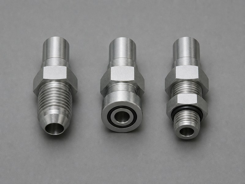
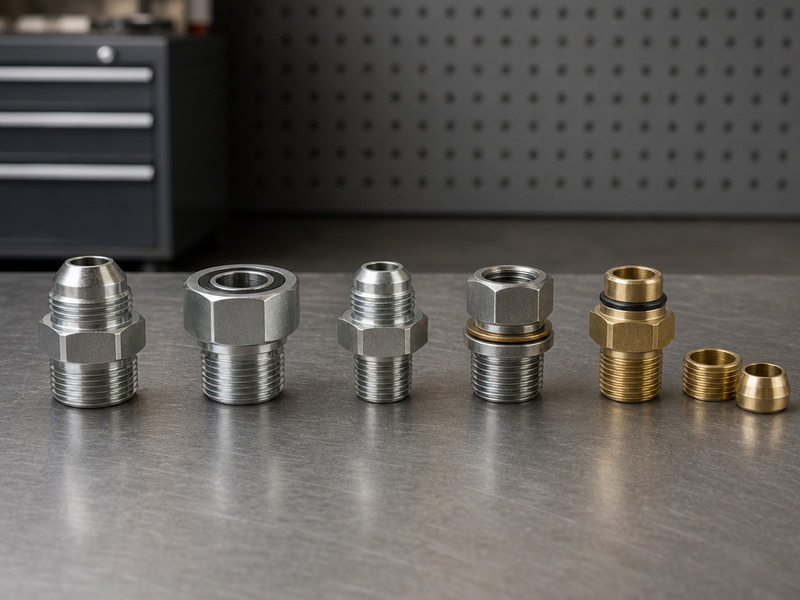
Figure 3. JIC 37° flare, O-ring face seal and O-ring boss ends side by side. The threads hold the connection together; the seat is what seals it, so identify the seat before ordering.
How to Measure an Elbow Fitting’s Angle
Elbow angle is a separate measurement that determines whether the assembly can be routed without a twist. For a 45° or 90° elbow, the angle is measured between the axis of the hose and the axis of the port end — and on the assembly drawing it is normally stated with an orientation reference, because a correctly bent elbow that points the wrong way is still a rejected part.
Measure the angle by sighting along the hose axis and comparing the port end against a protractor or an angle gauge. Record it as 0° (straight), 45° or 90°, then record which direction the elbow points relative to a reference feature on the other end of the assembly. That orientation note is what tells the hose builder how to clock the second coupling during crimping.
How to Measure a Hydraulic Hose: The Tools You Need
You can complete all three measurements with four tools, and only one of them is expensive. The point of the list below is that no single instrument covers all three dimensions — a tape measure cannot read a bore, and calipers cannot follow a curve. That is the useful part of how to measure hydraulic hose: the difficulty lives in the sequence, not in the tool kit.
Table 6 – Tools for measuring a hydraulic hose, and which measurement each one serves
| Tool | Measurement | Notes |
|---|---|---|
| Soft tape measure, metric and imperial | Length, bend radius | Must be flexible; a steel rule cannot follow a hose centre line through a bend |
| Digital calipers, 0–150 mm | ID, thread outside diameter | Read the bore at the cut end and the thread on the male thread only |
| Thread pitch gauge, inch and metric | Threads per inch or pitch | Two gauges are needed; inch and metric leaves are not interchangeable |
| Sizing dowel, pin gauge or bore gauge set | ID | Fastest field method and removes the conversion step if the set is marked in dash sizes |
| Angle gauge or protractor | Elbow angle, bend radius check | Used to record 45° and 90° ends and their orientation |
| Hose cut-off machine or fine-tooth saw | Preparing a measurable cut end | A ragged cut distorts the bore and makes caliper readings unreliable |
| Paint pen and camera | Reference marking and record keeping | Marks the sealing faces before measuring and photographs the original routing |
The one tool that repays its cost fastest is a bore gauge set marked in dash sizes, because it removes the two steps where mistakes are most likely: converting millimetres to a dash size, and misreading an oval bore. A thread identification kit, which pairs a pitch gauge with thread and seat gauges, is the equivalent shortcut for the fitting end of the job.
How Do You Measure Bend Radius and Fitting Angle?
Bend radius is not one of the three ordering dimensions, but it is the measurement that decides whether a correctly sized hose survives. A hose that is the right length, the right bore and the right ends can still fail early if it is routed tighter than its published bend radius allows.
Minimum bend radius is measured to the centre line of the hose at the tightest point of the curve — from the centre of the bend arc to the centre line of the hose, which is the convention a hose datasheet uses. Where a supplier publishes the figure to the innermost surface of the bend instead, add half the hose outside diameter before comparing the two figures on the same basis.
To check a routing:
- Find the tightest curve in the installed path. That is the one that matters; the rest of the run can be generous and still not compensate.
- Measure from the centre of the bend arc to the centre line of the hose, using a soft tape or a bend template.
- Compare against the hose’s published minimum bend radius for that construction and bore, taken from the hose datasheet.
- If the measured radius is smaller than the published minimum, change the routing, add a bend restrictor, or move to a hose construction with a tighter bend capability.
Two things make this measurement less simple than it looks. The first is that a hose bends more tightly at zero pressure than at rated pressure, so a routing that looks acceptable in a parked machine can close up and kink under load. The second is that the achievable bend radius changes with construction — a four-spiral high-pressure hose of the same bore has a larger minimum bend radius than a two-wire-braid line, because the heavier reinforcement resists bending.
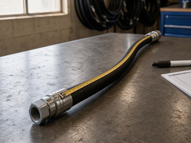
Figure 4. Centre-line measurement: the same principle sets the assembly length you order and the bend radius you route to — here, the length, reference point to reference point. Following the outside curve of a bend, or measuring to the outer edge of an elbow, will produce an assembly that is consistently long.
Which Measuring Mistakes Cause the Wrong Hose to Arrive?
The failures below account for the overwhelming majority of replacement assemblies that do not fit. Each one is a definition error rather than an instrument error, which is why buying better calipers does not fix them.
Length Mistakes: The Five That Make an Assembly Long or Short
- Measuring along the outside curve of a bend. The outside curve is longer than the centre line. This over-states length on every hose with a significant bend in it.
- Measuring the old hose under tension. Pulling a hose straight to lay it flat adds length. Let it relax first, and straighten it by hand only.
- Measuring to the outer edge of an elbow instead of to the centre line of the sealing surface. On a 90° end this alone can add roughly half the elbow width.
- Forgetting the O-ring face seal rule. ORFS ends are measured seat to seat, not end to end. Measuring an ORFS assembly end-to-end over-states its length by the depth of both nuts.
- Forgetting crimp growth. The cut hose and the finished hydraulic hose assembly are not the same length. Crimping adds length, and on a long assembly it adds enough to matter.
Bore and End-Connection Mistakes: The Five That Make an Assembly Unusable
- Measuring the hex nut. Hex size is a wrench dimension. It tells you nothing about the thread or the seat.
- Reading a hydraulic hose dash size off the outside diameter. There is no fixed relationship between hose OD and bore, because OD changes with the number of reinforcement layers.
- Recording only one end connection. Mixed-end assemblies are common. Capture both ends separately, including the seat type of each.
- Leaving out elbow orientation. A 90° elbow pointing the wrong way is a rejected part even though every dimension is correct.
- Mixing metric and imperial in one record. Converting 12.7 mm to “12 mm” for convenience is how a -8 hose becomes an M12 line on the order.
How Do You Write the Measurements Down for a Supplier?
A supplier can quote accurately from a complete measurement record and cannot quote at all from a partial one. The template below is the minimum information needed to build a replacement hydraulic hose assembly without a follow-up call — and if you have already measured an old assembly rather than a new requirement, this is also the record that lets a supplier flag a problem before the hose is built.
Table 7 – Measurement record template to send with a hydraulic hose enquiry
| Field | What to record | Example |
|---|---|---|
| Assembly length | Reference points used, plus the figure | Seat to seat, 1,240 mm |
| Measurement basis | Installed routing or loose hose | Measured installed, on machine, depressurised |
| Dash size or bore | Dash size and measured ID | -12, measured 19.0 mm at cut end |
| Hose construction | Marking line data from the cover | Two-wire braid, 1/2 in equivalent |
| Working pressure | System working pressure, not just rating | 210 bar working pressure; minimum burst pressure four times the maximum working pressure (EN 853 / SAE J517, per the standard marked on the hose) |
| End 1 | Seat type, thread, elbow angle, orientation | JIC 37° male, 1-1/16-12, 90° elbow, points to port side |
| End 2 | Seat type, thread, elbow angle, orientation | ORFS female swivel, 1-3/16-12, straight |
| Fluid and temperature | Fluid type and temperature range | Mineral hydraulic oil, -20 °C to +100 °C |
| Environment | Abrasion, UV, wash-down, external heat | High abrasion, exposed to UV, steam wash-down |
| Quantity and date | Units and required delivery | 6 pieces, required in 3 weeks |
Record the measured bore next to the hydraulic hose dash size rather than instead of it. The two can disagree by a few tenths of a millimetre while both being correct, and a supplier who can see both figures immediately knows whether the hose you measured is inside its tolerance band or is a different construction from the one you assumed.
Two fields on that template are the ones people leave out and then regret. Measurement basis matters because a length taken from an installed hose and a length taken from a loose hose are not interchangeable numbers. Elbow orientation matters because it is the only field that cannot be recovered from the old part once it has been cut off.
If you are still deciding what to specify rather than how to measure what you have, our guide to how to choose the right hydraulic hose covers the selection decisions that sit upstream of measurement, and the hydraulic hose sizes explained reference covers ID, OD and dash size in more depth.
The Enquiry Sheet a Distributor Can Quote From
The field order below is the same one Table 7 uses, so a completed record can be copied straight into a quotation with nothing to re-key:
- Dash size or bore, and the measured ID.
- Hose construction, from the marking line on the old cover.
- System working pressure, including any surge figure.
- Fluid and the maximum and minimum operating temperature.
- End 1: seat type, thread, elbow angle and orientation.
- End 2: the same four fields.
- Overall assembly length, and the measurement basis used.
- Quantity, required date and whether a test record is needed.
- Any standard the assembly must meet.
Is the Old Hose Still the Right Size?
Three outcomes are possible when you compare the measured bore, or the measured length, with the nominal figure:
- Inside the band. The reading sits within the ID tolerance and inside the length tolerance band for its size, so the old hose is a valid size reference and can be ordered again as measured.
- On the edge of the band. The reading sits within tolerance but within half a millimetre of the limit. Record the measured figure as well as the nominal dash size, and let the builder confirm against their own tolerance band.
- Outside the band. Either the hose has been replaced with a different size, or the construction has changed and the bore has drifted. Order from the measured bore and the marking line, not from what the old part was assumed to be.
The same three-outcome test applies to length once the effect of working pressure is allowed for: a hose can be up to about 4 percent shorter than its first-pressurised length, so a reading taken cold is not the same as the reading taken in service.
Frequently Asked Questions
Can you explain how to measure hydraulic hose ID if the hose is still installed on the machine?
You can narrow the bore while the hose is still installed, but you cannot confirm it. Read the coupling’s inner bore or the port bore as a candidate value, then confirm it once the old hose is off the machine: ID is measured at a clean square cut with the reinforcement exposed and no coupling in the way. Treat any in-place figure as a shortlist rather than the number you order from.
Is a -8 hydraulic hose the same as 1/2 inch?
Yes. Dash size is the nominal inside diameter in sixteenths of an inch, so 8/16 in is 1/2 in, which is 12.7 mm. Note that this is a nominal figure: the standards allow an ID tolerance, so a caliper reading on a -8 hose will often sit slightly either side of 12.7 mm without the hose being out of specification.
How do you measure a JIC fitting?
Measure the male thread across the crests with a caliper and expect a UNF size: a -6 JIC is 9/16-18 with a thread outside diameter of about 14.3 mm, and a -8 JIC is 3/4-16 at about 19.1 mm. Then confirm the seat, because the thread alone does not name the fitting: a JIC end shows a 37° cone on the male nose with straight, parallel threads behind it. A cone that looks shallower and wider is an SAE 45° flare, and the two will screw together without sealing.
How do you identify a hydraulic fitting if you do not have a thread pitch gauge?
Measure the thread outside diameter with calipers, then cross-check against a thread chart. If two candidate threads share that diameter, you need the pitch: lay a steel rule along the thread, count crests over one inch, and compare. Failing that, screw the fitting onto a known matching adapter — but only to confirm, never as the sole method, because two different thread series can start to engage before jamming. This is the one step of how to measure hydraulic fittings that no chart can complete for you, because a chart can only offer candidates.
How do you measure an ORFS or O-ring boss fitting?
Both use a straight thread, and the two families do not share sizes: an ORFS -6 is 11/16-16 while an O-ring boss -6 is 9/16-18, so the caliper reading separates them immediately. What they do share is the principle — the O-ring makes the seal and the thread only holds it — so finish with the seal feature. An O-ring sitting in a groove on a flat face is ORFS and appears on the hose end; an O-ring under the hex, seating against a chamfer, is the boss port, and its size is confirmed from the port rather than from the fitting.
Is hydraulic hose size the same as diameter?
Not quite, and the difference causes real ordering errors. Hose size is the nominal dash size: a -8 hose is nominally 1/2 inch, or 12.7 mm, of inside diameter. A diameter on its own is ambiguous, because a hose has two of them and the outside diameter changes with the construction — a -8 hose measures about 20.0 to 21.4 mm outside as a single-wire-braid line, about 22.5 to 23.0 mm as a double-wire-braid line and about 23.8 to 25.4 mm as a four-spiral high-pressure construction, while its bore stays nominally 12.7 mm in all three. Always record which diameter you measured.
How much shorter should I cut a hose to hit a target overall length?
That depends on the coupling take-up at each end, which the fitting manufacturer publishes for each hose-and-fitting combination, so the reliable route is to specify the overall length you need and let the builder work back to the cut length. As a sanity check on how much that difference can amount to, a documented distributor bench test built a 1-1/4 in hose to a 26 in target and measured just under 26.5 in once the couplings were crimped on, so the cut tube was shorter than the finished assembly by roughly the sum of the two take-ups.
How much length change should I allow for at working pressure?
It is a two-sided allowance, and the two published figures are measured from different baselines. Against its relaxed bench length, a hose under working pressure can elongate by up to about 2 percent; measured against the same hose when it is first pressurised, one that has taken a compression set can read up to about 4 percent shorter. Size the routing for the shortest condition so the couplings are never pulled, and leave clearance for the longest so an already tight bend does not close up under load.
How accurate does a hose measurement need to be?
Accurate enough to land inside the tolerance band the builder can hold — ±1/8 in for assemblies up to 12 in, ±3/16 in from 12 to 18 in, ±1/4 in from 18 to 36 in, and ±1% of overall length above that. If your routing window is narrower than those bands, tell the supplier when you order, because a standard build cannot guarantee a tighter figure.
Final Verdict: Measure Three Numbers, Not One
Learning how to measure hydraulic hose is not difficult, but the job is unforgiving, because a replacement assembly is built to the numbers you supply and nothing else. The whole discipline reduces to three separate measurements taken in the right order: length end to end between the correct reference points for the seat type, ID read at the cut end and converted to a dash size, and end connection identified by thread outside diameter, thread pitch and seat type.
Get those three right and the rest is arithmetic — crimp growth, length tolerance, bend radius and pressure-induced length change. Get any one of them wrong and no amount of care downstream will save the assembly. One figure is never yours to derive: the hose standard marked on the layline (SAE J517, or the EN 853 / EN 857 family) fixes the minimum burst pressure at four times the maximum working pressure.
If you would rather have the measurement checked than build the hose twice, send us the routing or the length, the marking line from the old cover, and a photograph or measurement of both ends. Our engineers will confirm the seat types against the thread chart, sanity-check the length against the tolerance band and the minimum bend radius, and tell you before we build whether the assembly you described will actually fit. Contact HENGHUA for a quote and free samples.
About HENGHUA
HENGHUA manufactures hydraulic hose and hose assemblies for construction, agricultural, mining, material handling and industrial equipment — for OEM programmes, equipment distributors, repair workshops and MRO buyers. Our range covers the standard inch-series bore sizes from -4 through -32 across one- and two-wire braid, multi-spiral high-pressure and return-line constructions, in the dash sizes and bore tolerances used on the equipment we serve.
We build from data, not from a sample part. Because we cut, strip, crimp and test in-house, we can work to a supplied measurement record — assembly length, dash size, both end connections and the elbow orientations — rather than requiring you to post a physical hose. Where a measurement record is incomplete, our engineers will query it before production starts rather than after the hose has been crimped.
The pressure data travels with the assembly. Each assembly is proof-tested and the test record is filed against the assembly reference, so the documentation matches the part in your hand rather than the part in the catalogue.
If you are replacing a hose and want the measurement verified before you commit to a batch, send us what you have: the routing or the length, the marking line from the old cover, and a photograph or measurement of both ends. We will confirm the dash size, identify the seat types, check the length against the tolerance band, and come back with a quotation that separates hose body, couplings, testing and delivery so you can compare it line by line. Start an enquiry with HENGHUA.
Written by the HENGHUA engineering team — hydraulic hose design, assembly and testing.
 English
  Spanish
  Portuguese
  French
  German
  Arabic